
Robot Journal - John
02/24/12
E-mails: check. Phones: calm. Weather: cold. As I lick my finger and raise it up to test the air in the office, I think to myself: The conditions are prime to get my hands shocked and my brain gears turning for the tech support project to come. Concepts and ideas run through my mind as though I'm trying to figure out the meaning of life -- which we all know is 42 -- but that is beside the point. I need to make a modular, 12x12-inch acrylic floor piece, ¼-inch thick, for our robot battle arena.
Due to the concept of the competition, I do not want to make something that is going to destroy robots. I want to make something that briefly incapacitates them and then lets them go. After giving it some thought, I decided on a platform where spikes will protrude from the bottom, then lower back down slowly, so as not to hurt the robot. Time to get designing.
First thing's first, I needed concept sketches of this idea:

As you can see, I had a few ideas for how to go about building this floor piece. The top left concept involved four solenoids (I only drew two), one in the center of each side of the inside of a 1-foot acrylic square. The idea was to use some spikes (probably framing nails) and have them sit right below a platform that concealed them. Then using a few Arduinos and power driver shields, I would have had them periodically (possibly even randomly) apply power to the solenoids, causing them to violently shoot the spikes up. I might not get to the prototyping phase for this, due to the possibility of damaging someone's robot.
The bottom right sketch was going to be a DC motor attached to the side of an acrylic, 1-foot square. This is basically the same concept as the solenoids, except the motor attached to the crank could allow the spikes to move up and down more fluently and slowly, depending on how I powered the motor. The blocks on the two sides are to keep the spike platform from caving in, and to keep it in place while the crank comes back. The crank would have been oval in shape to allow for a smoother transition for the spike raising and falling. This might not make it into a prototype phase either.
The sketch in the bottom left corner is going to use our linear stepper motor with a threaded shaft for the motor to climb up and down. This sketch is the most appealing to me and it appears to be the most realistic for our robot competition. I plan on attaching the spike’s platform on the stepper motor and having the platform move with the motor. I will be using an Arduino and an Easydriver along with the stepper motor. The Arduino can be programmed to make the stepper motor move at a slow pace so that if a robot gets caught on the spikes, it will stay incapacitated for a few seconds.
After mulling over my sketches, I decided that the stepper motor wins. Now, I have to make the concept into reality. Thankfully, I have a lot at my disposal here at SparkFun. There is a company not far from here that sells acrylic scrap sheets in different shapes and sizes for fairly cheap, and SparkFun has a nice laser cutter as well. The next step is to design the acrylic pieces.
03/02/12
All responsibilities are diminishing. The workload has shrunk significantly since Monday, and it looks like it's time to design a few things. I have some great ideas I want to try for this project, and I have the acrylic to make mind into matter; it's time to MacGyver some stuff up!
First, I drew and measured everything and incorporated it into Inkscape. Instead of showing all of you the files, I will take a picture of the finished cut product. I currently have four different files for the floor piece. It will consist of a bottom piece, a two-layer mid-section, and a top piece. I plan on putting another top piece on it, but I will save that for another time.
Here is what I managed to produce:
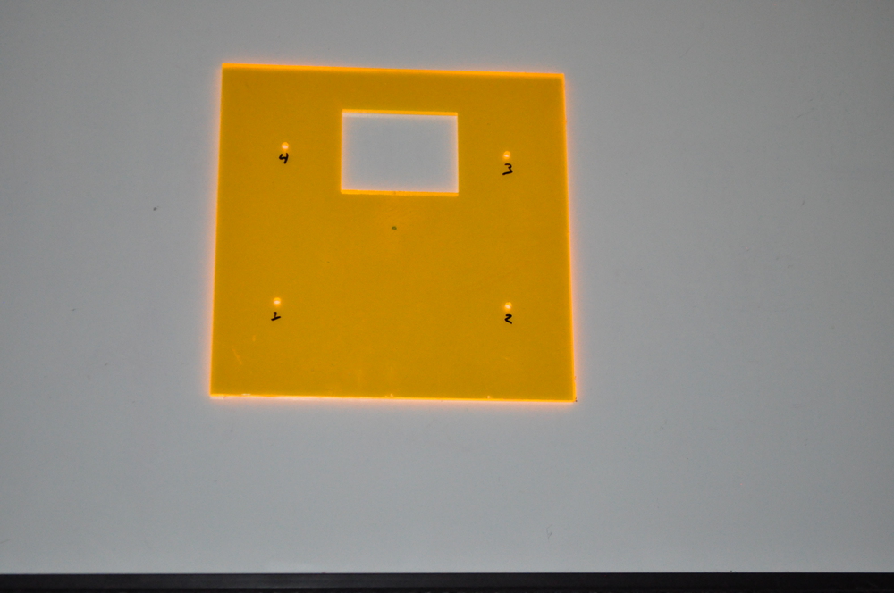
This is going to be the bottom floor piece. The stepper motor's six-wire connector side is going to be facing the side with the large rectangle cut out, for easy wiring. The numbered holes are going to have a metal shaft go through them that I got out of empty toner cartridges. I basically scraped the foam padding off the cylinder and cut it in half to act as guide rails for the motor and support everything structurally.
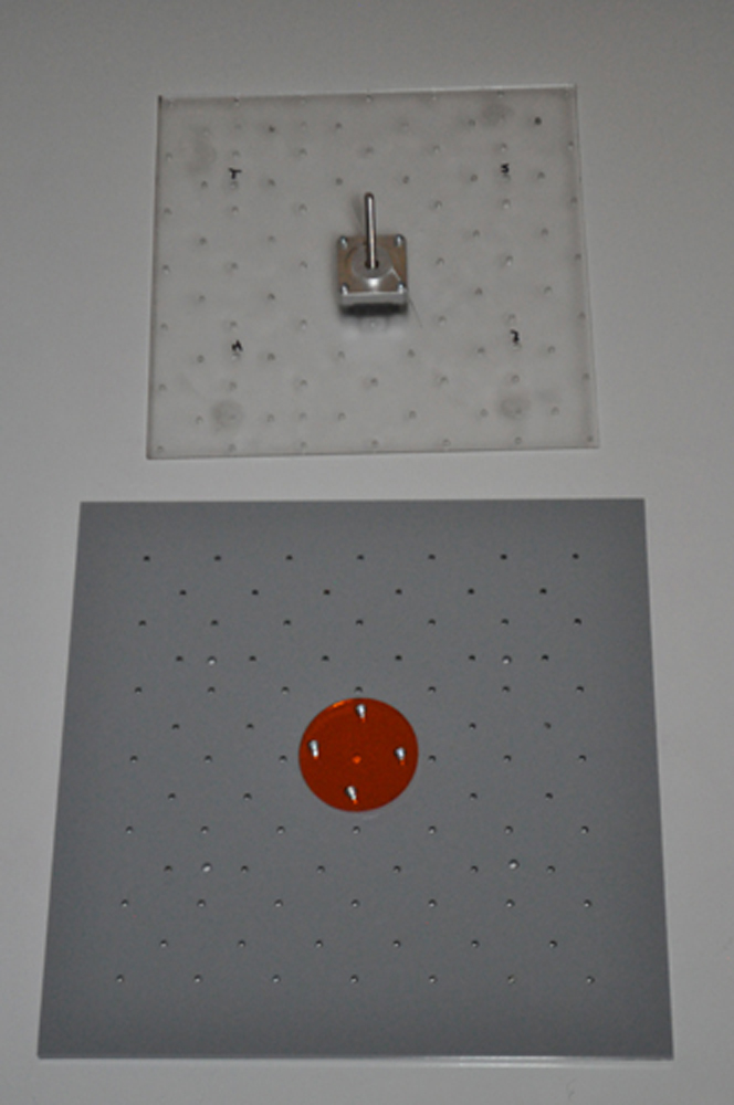
The clear piece is going to be the center platform for the framing nails and stepper motor, and the bottom piece in the picture is the top piece that robots will be driving on. The orange disc in the center is supposed to provide tension on the stepper motor’s shaft, and has two functions. The first is if the motor comes to a point where it can not proceed on the shaft, the shaft itself will spin freely instead of the motor stalling. The second is to keep the shaft in place so the motor can move freely along it.
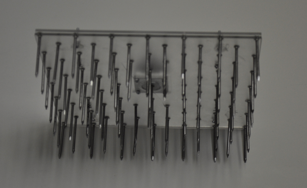
This is two pieces of clear acrylic sandwiched between the heads of the nails. I actually cracked one of the pieces of acrylic by accident from screwing the stepper motor on too tight. The motor is actually screwed onto the top piece -- the one with all of the nails sticking out -- and the only purpose the bottom piece serves is to keep all of the nails from falling out. There are also the four numbered holes on both of these pieces, along with four other holes used to screw the two pieces together with 4/40 nuts and screws.
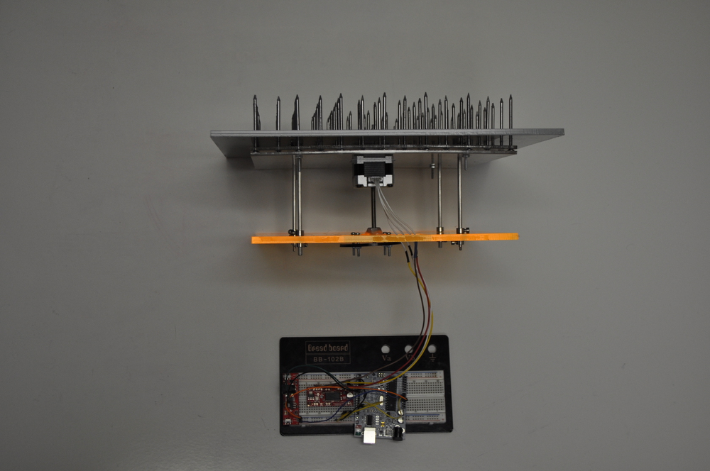
This is the assembled floor piece. As you can see, I have a Arduino Uno and Easydriver stepper motor handling the motor’s functionality. The third board is just a breadboard power supply. It will not be used in the final stages, only for prototyping. There are the four metal shafts I was referring to earlier. I also have a shaft collar sandwiching the bottom and top platforms to keep them in place using a total of 16 shaft collars. There is also another “tension disc” on the bottom platform for the stepper motor shaft. I actually put some basic code on my Arduino and modified a few things and sure enough, the spikes move with the motor fluently enough. This is a great day for robotic arenas everywhere!
4/6/12
Alright, second phase of operation robot-battle-awesome-mania: Build the actual robot. I spent a great deal of time on a whole bunch of weapon designs, defensive strategies, robot chassis for all of my embedded electronics and the wireless controller used to control the robot. It's time to make the robot that will win the tournament, give robots everywhere a reason to keep fighting, and humans a reason to keep fearing!
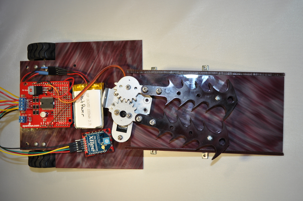
Here are a bunch of components and partially made prototypes of the robot that I may or may not use:

What we have here is:
- 2 Xbee series 1 modules with chip antenna (definitely using these)
- 2 Xbee explorer regulated board, a Xbee shield (for prototyping)
- A disassembled PS2 controller
- 1 fully assembled robotic claw with medium servo
- redesigned robotic claw using two double-edged laser cut acrylic blades with medium servo
- large servo with custom made lance (toothpick) slicer, AKA “The Grinder," made out of small rigid washers and solder
- FTDI Basic 5v for both the Arduino Pro Mini 3.3v and the 5v Pro under the Ardumoto shield
- Arduino Uno for prototyping
- prototype robot platform
- 2 gear motors
- 2 custom acrylic gear-mounting pieces
- 2 off-road rubber tires
- 2 1150 mAh batteries wired in series
All of these items have been tested and are working. The first thing to work on would be the controller, since it's in my skill range.
First, I chopped off the PS2 controller's cable and left about 4 inches of wires. Next, I gutted out both of the vibration motors in the PS2 controller's handles and cut out the two screw mounts (hollow holes at the bottom), giving me plenty of room for my Xbee, Xbee explorer regulated and Arduino Pro Mini 3.3v and wires.
After everything fit snugly, I pondered what to do about a battery. I thought to myself, “No way l am I going to fit a battery in here, it's a little too busy." As you can see in the picture, I decided to just drill two holes into the center where the analog sticks sit, and I put a 2” 4/40 screw through each hole. I then put two spare servo horns and two 4/40 nuts on there and put the battery on, essentially screwing it on snugly but not tightly.
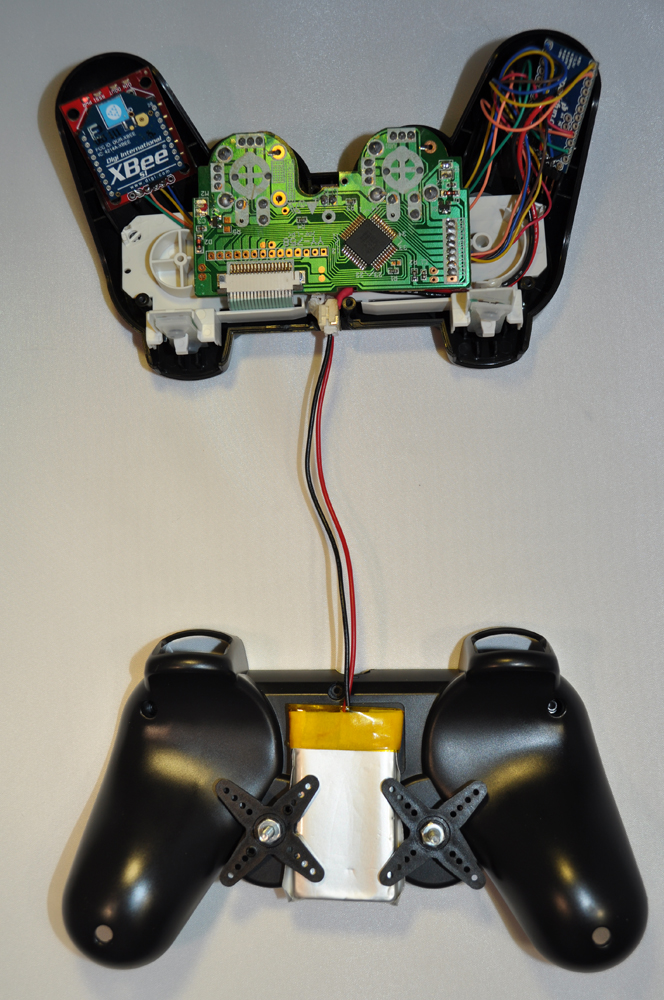
The final step is soldering all the wires where they need to go. I put a SMD JST connector where the controller’s cord used to come out (I had to shave a lot of plastic off so it would fit), with two wires coming off it. Then I soldered GND and PWR to the Arduino Pro Mini’s GND and VCC pins located where you plug in an FTDI basic for programming. The battery was not plugged in while I did this, of course.
I then wrapped up the PS2 controllers and Xbee explorers GND and PWR, and soldered them to the Arduino’s corresponding pins. After this, I soldered the PS2 controllers wires to the Arduino Pro Mini 3v based on the Arduino projects link diagram on the PS2 controller's product page.
After all the soldering, I tested the controller to make sure it worked, and it had a couple issues. My buttons were not responding when pressed. First thing I did was test continuity between the multiple pin ribbon and connector located in the bottom left part of the controller's green PCB. Turns out there was no continuity on a few pins responsible for the buttons I was going to use, so I moved the ribbon over. No harm no foul; it works now.
Second, I noticed that my Xbee was flickering, no good. I went and cleaned all of the solder joints on both the Xbee and Arduino Pro Mini that had excess flux on them and sure enough, the problem disappeared. Clean that flux off people! After all of this, the controller works great!
4/13/12
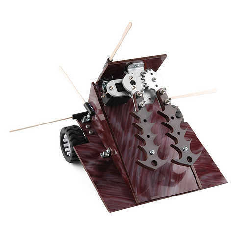
Alright, another great day to meddle with robots. After getting the controller up and running, it was time for the main robot. I went ahead and laser cut another 6x6-inch square with spaces cut off for the tires, cut a 3x6-inch ramp with two angled sides, and drilled the appropriate holes needed for the little 4.40 “L” brackets SparkFun sells. The rest of the components should be obvious from my previous picture.
Here we go! This is what I have decided to use for my final robot. Now, there were actually a lot of issues with this robot while I was building it up and testing it out. I lazily drilled holes on the platform for my components and ramp to screw on, which all ended up being uneven, and I glued the sides of the ramp on and taped the battery to the platform. If you have access to a laser cutter, use it!
There were also some hardware issues with the electronics. I ended up frying two 850 mAh lipo batteries and a medium servo while testing the robot for the following reasons:
- My code was asking it to open and close at 180°, and the gears were apparently so tight that the servo would tense up at both the open position and close position, causing problems with the servo's circuit, along with the batteries. I had to really loosen those gears and redo my code to leave a gap in the close position and only go 90° in the open position.
- I was rather paranoid about frying even more batteries, so I ended up putting a diode in the batteries' circuit before it got to any components, hopefully saving me a couple batteries, which it did. Hooray!
- Another issue I had was that my batteries' output is 7.4V, and my servo can take 4.8-6V max, so the servo would not play well with other components when being powered from the Arduino (constant circuit reset). I needed to find a way to solve this issue. What I had to do was grab a PTH 5v regulator and solder it to the proto part of the Ardumoto, and have the batteries' power hit the voltage regulator to get the output to 5v and go to the servo, completely bypassing the Arduino.
I am looking forward to the robot competition on 4/20/12. After all of the time and effort tech support put into all of our individual robots and floor tiles, this is going to be awesome. My robot and floor piece are in perfect working condition and ready to make history here at SparkFun and for robots everywhere! Here is what everyone will see on the day of the battle, and it is going to be glorious:
id lov to see it in action