
Robot Journal - Michelle
Let's Make a Robot
A robot to defeat all robots ... wait, what do you mean I didn't win? Well, it was a nice try anyway.
For all those who are curious as to how a tiny, 6-inch battle bot is made, want to know more about the design process, or just want to know why I hate coding, then this is the tutorial for you. As a summary, I have a circular bot with two servos running the wheels and a stepper on top that spins a mace around. Nothing like building a wrecking ball onto your bot.
Parts list
I started by looking through the SparkFun motors for the one with the highest torque, which led me to the full rotation servos (steppers are way too heavy to even consider). I also like servos because I don't need a motor controller, I can just plug them into my Arduino and get them to work.
I knew I needed two servos; I was using an Xbee for wireless and decided on the Fio since I like them. I ended up using a really old Fio I had lying around for most of the prototyping, since the new Fios weren't ready, but I ended up using the new ATMega32U4 Fio for the final bot. It was nice to have the two UART lines so I could connect my Xbee to receive commands and still debug over the USB cable.
Chassis Design
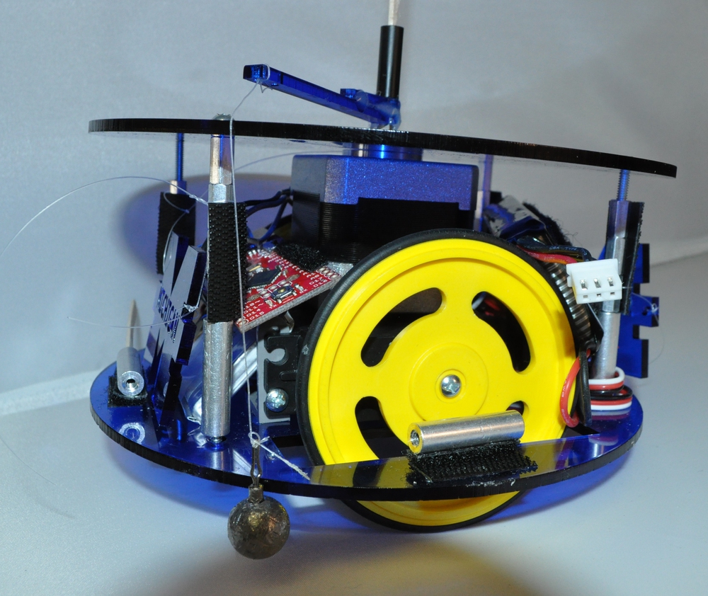
Once I had the motors and wheels figured out, I needed to figure out how I wanted to design the bot. I knew I wanted a large weight swinging around, so I decided that a round robot would cause the least amount of snags in the line. By the time the servos and wheels are taken into account, though, it didn't give me much room to make design changes.
I had two servos, an Arduino, and some servo wheels I borrowed from Mike (thanks Mike!), so I grabbed Inkscape and got to work. The first prototype was just printed on paper, & then I grabbed the parts and made sure things fit. At this point I had a fairly finished design and Tim needed stuff to print on the laser printer. So I ended up with a cardboard piece (cardboard's a bit stiffer so it's easier to line stuff up). Then it was time for acrylic ... I grabbed some screws and everything fit. But I still needed to find a way to mount the servos.
Tim suggested some brackets we had lying around that were designed for mounting servos, so out came the calipers and a lot of math. Again, cardboard and acrylic and mounting. The original acrylic piece worked well as a top piece for the moment. At this point I had a decently put-together bot so it was time to work on the code to get it to drive around properly.

Code Part 1
A few years ago I had done a small robot that could be controlled from my netbook using W, A, S and D. It worked great for that, but when I tried to port it to a joystick it didn't work so well. What do you do with a 45-degree angle, etc.? So I decided to write new code. This code got a bit crazy, but basically the idea was this: The device reads the joystick and a few button presses, calculates angle and velocity (based on how far I'm pushing the joystick out), and then mushes them all together and sends out one fairly big number. I thought about doing each value separately, but then you need things like start bits, so I decided against it.
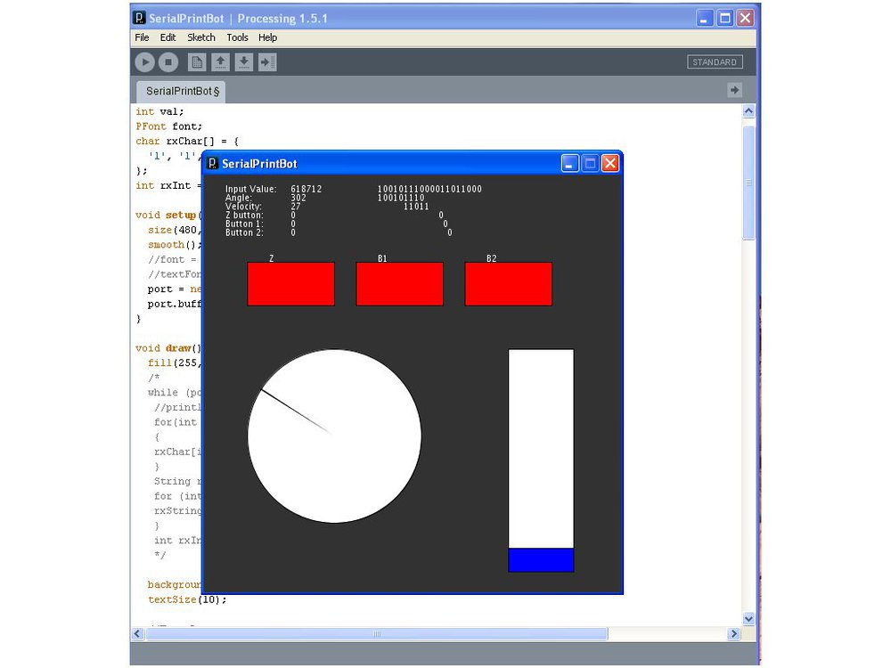
So after playing around a bit, I had a joystick calculating values and mashing them together. But would the unmashing work, and was it mashed together properly? How would I know if the joystick was being weird, or if the bot just didn't like driving at 45 degrees? Well, I decided to write a Processing script to read the data, use the same decoding functions as the Arduino on my bot, and then display those values both numerically and graphically. Processing is surprisingly easy to use. Having never used it, I was able to have it show my graphics and print some data in an afternoon. Getting the Serial data from a character array to a String, and then to an Int, was another story though.
Once I found all my bugs in the Processing script I was able to view the data being sent. But it still wasn't right (this is why I wrote the sketch). So I went back to the joystick code to see if I could get the data working. I did a bit of tweaking, and remember -- if you only have one byte, 256 is not a useful number. Now I have working joystick code!
More Coding
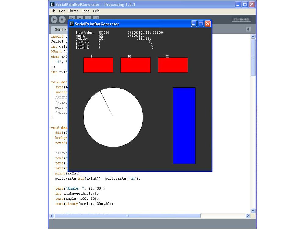
I got the processing code working, but my bot didn't want to follow anything resembling commands. So I figured since I was now a pro in Processing, and had code for a graphical representation of my data, I'd make a quick program that would send data to my bot to help me de-bug. If the picture looks similar to the last sketch, it is. But in this case, it reads the mouse pointer values and calculates angle and velocity, and can tell if you are hovering over a button. It definitely has some glitches, but it gets the job done; I'm able to manipulate the data, test different functions and see the actual values I'm sending.
I Hate Coding
I finally got the bot driving (at least forwards, backwards, left and right -- angles still aren't working), so I figured I'd start on the weapon. Servo or stepper, servo or stepper? Or maybe a DC motor. My original plan was a stepper, but they seemed like big, bulky overkill. Not to mention they need 12V; you can get away with less, but my 3.7V lipo wasn't going to make it. Servos, on the other hand, tend to cause problems on Arduinos when you start using too many of them (basically more PWM pins than timers). I started coding and decided on stepper.
Then I remembered that you can't just turn steppers on. You tell them to take a step, then another, then another, with small delays in the code. This works great by itself, but not as well with other code that has delays. On the other hand, I'm not picky about my steppers. Just keep going, if you need to take a break to turn on a servo, that's fine. Basically my stepper function is set up to be about the time of the delays my servos need. The code's working -- now to solder Easy Drivers, find batteries, and build a breakout board to add all my parts.
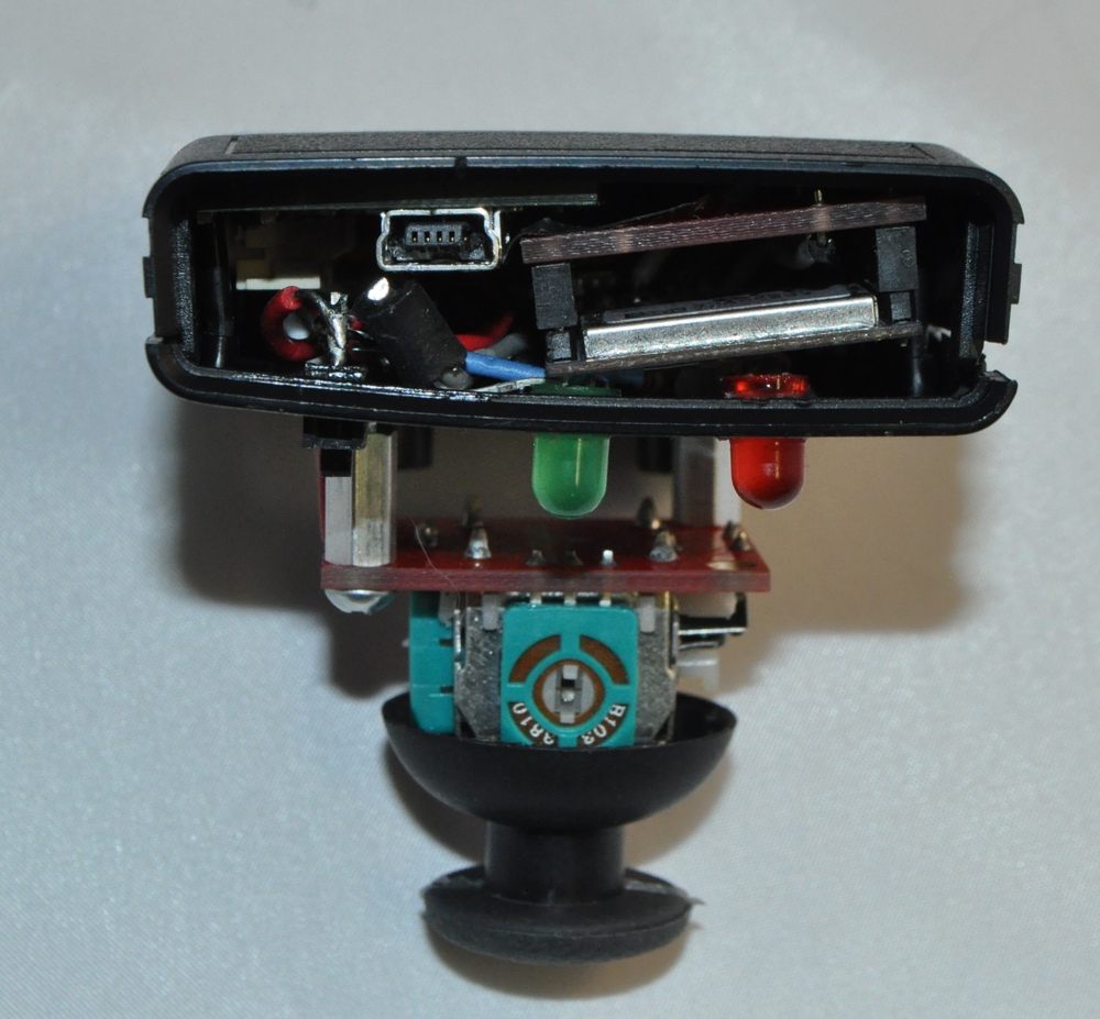
Joystick
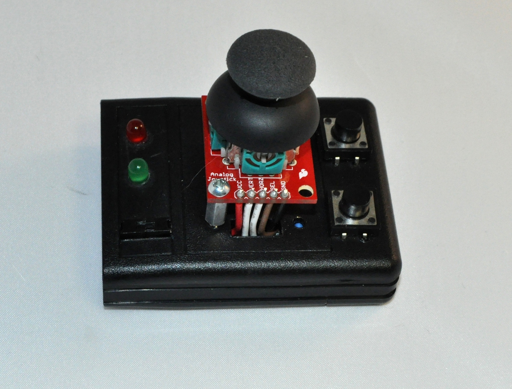
Then came the joystick. A few months ago Dia built an arm cannon that had a joystick built into a piece of plastic from the conductive thread spools. It caught my attention and I decided to turn one into a full joystick. I grabbed a thumb joystick, a Pro Mini, a tiny battery charger and a Lilypad Xbee board, since it's round and would fit in the bottom well.
Then came crunch time. I loved the idea of using the thread spool, but I just didn't have time. Not too long ago we discontinued our Witilt but still had a bunch of boxes sitting around. They looked like they would make good controllers, but hopefully they weren't too small. So I made a quick printout in Inkscape with a few mounting holes for some buttons, LEDs and mountint hardware and thought I'd try one out. It worked pretty well, so I grabbed my 110mAh battery, a Pro Mini, and Xbee breakout (and Xbee) and a board I had designed recently that combines an FTDI breakout with a Lipo charger. I started soldering to the LEDs, buttons, joysticks and each of the boards. Let's just say it was a tight fit and I never got the side piece to line up and work well with the USB port, but it adds to the charm.
Assembly
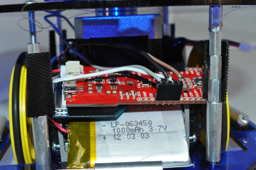
Tiny protoboards are your friends. I have two servos, one stepper, one Easy Driver, two batteries, and one Fio (with Xbee attached). I also wanted to have a separate switch to turn the motors on and off, since debugging when your bot is driving all over your desk is no fun, and a power LED for that.
With tiny protoboards and some imagination, I actually got everything to fit. These boards have the pads connected in sets of three, which sounds annoying but was actually pretty nice, as just connecting to components can get complicated. You need to connect holes, and when you have things sharing power and ground, etc., then those three pads become pretty nice. There is even a convenient mounting hole that I was able to use to connect the board to the servo mounts.
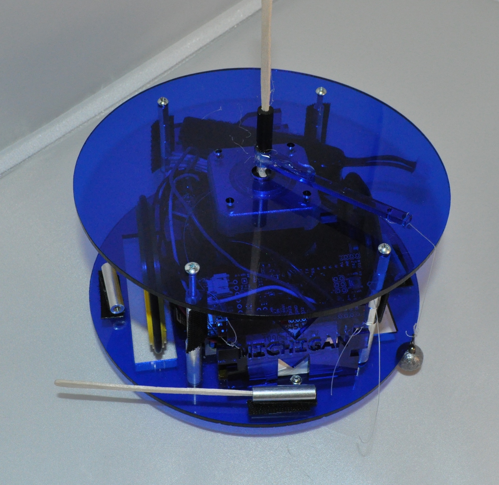
I finally got things working and it was time to assemble. It took a couple trips to the laser cutter, but the top plate is cut and isn't rubbing against the shaft of the stepper motor. I grabbed a few of the heaviest fishing weights I could find at Walmart (3/8 oz) and attached them to the stepper. Everything spun fine, but the fishing line just ended up winding around the shaft. So the day before the competition I designed some arms to help spin the weapon.
Everything worked fine until competition time when I realized that the connector was just too thin, and the arm kept coming off. Before the next competition the arm will be redesigned. Otherwise that's about it; last minute I cut some acrylic which I tied to the standoffs to prevent prying claws and weapons from pulling loose wires, but that's about it. Hope you learned something, now it's time to go design your own. Good luck and have fun!
Comments 0 comments