
Testing LEDs with fast-switching tweezers
In addition to making shortcuts for our customers, here at SparkFun we are also constantly making shortcuts for ourselves. Whether it's in our finance department or on the production floor, we are always looking to improve our systems and make our jobs easier.
This project originated from a task in our kitting department. Each time we make the Simon Says - Through-Hole Soldering Kit, we need to make sure that each kit gets four unique LEDs: red, green, blue and yellow. When these LEDs are not lit up, they are clear, and so it is impossible to tell their color. In the past, we have used a battery or multimeter to quickly light up the LEDs and verify the colors. This is pretty quick, but it requires getting the polarity correct and sometimes it can be difficult to touch each wire to each LED leg.
As the quality control manager here at Sparkfun, I have recently spent more time over in the kitting department. I've been helping them out with any ideas I may have for QC and system improvements. After seeing the pain of this LED testing procedure a few times, I thought, "How about a set of tweezers, a pro micro and some fast-switching?"
1) Gather all your parts!
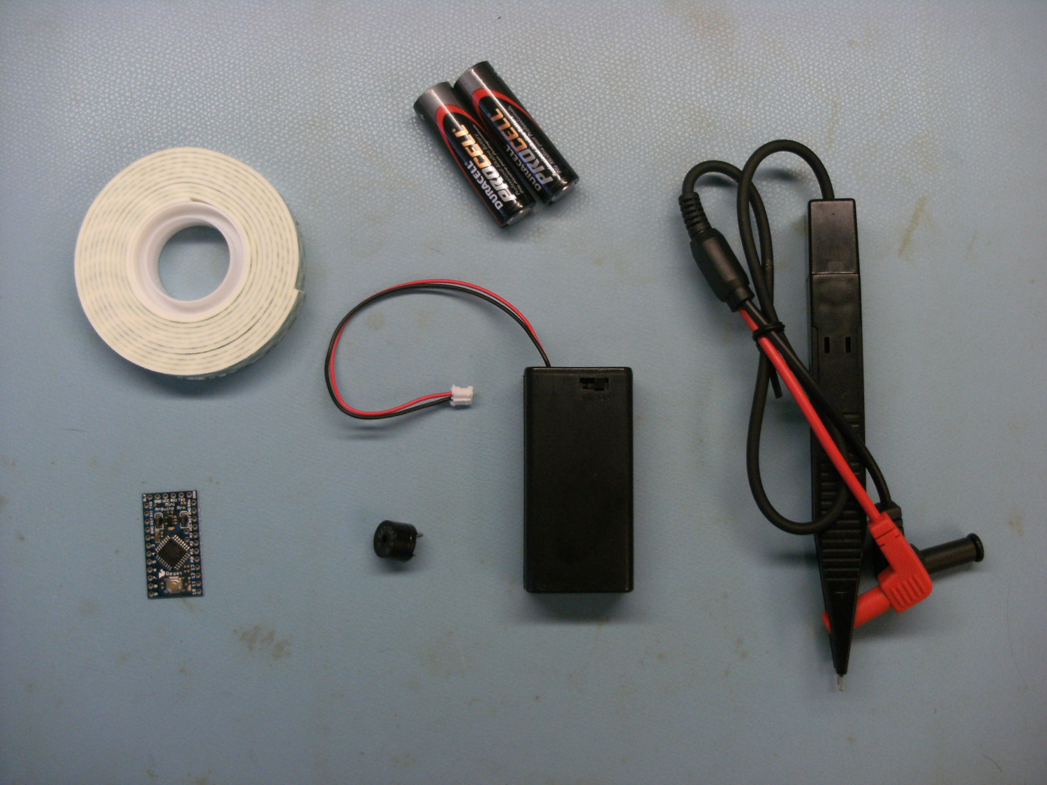
Parts that you will need:
- Arduino Pro Mini 328 - 3.3V/8MHz (or any Arduino platform of your choice)
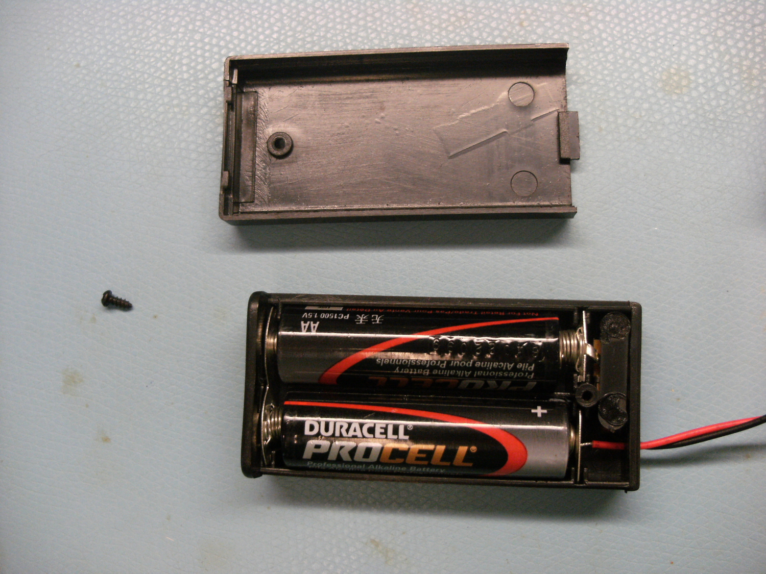
- Battery Holder 2xAA with Cover and Switch - JST Connector
- Multimeter Tweezer Probes
- 1500 mAh Alkaline Battery - AA (x2)
- Double-sided sticky tape
- Buzzer - PC Mount 12mm 2.048kHz (optional - this is for alarming when left on)
- FTDI Basic Breakout - 3.3V
Suggested additional tools:
- Wire Strippers 30AWG
- Soldering Iron Variable Temperature 50W
- Solder Lead Free - 10-gram Tube
- Hobby knife
- SparkFun Mini Screwdriver
2) Solder Tweezers
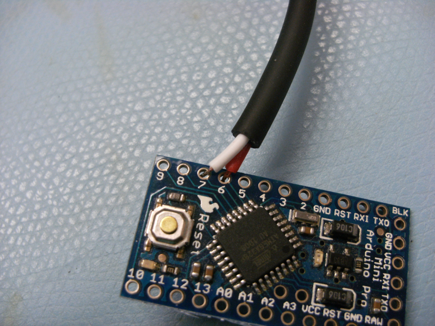
Cut and strip the two wires off of the tweezers. Twist each end to help avoid fraying.
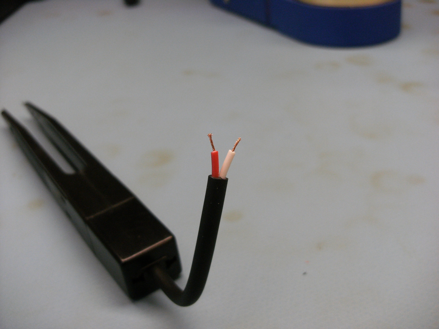
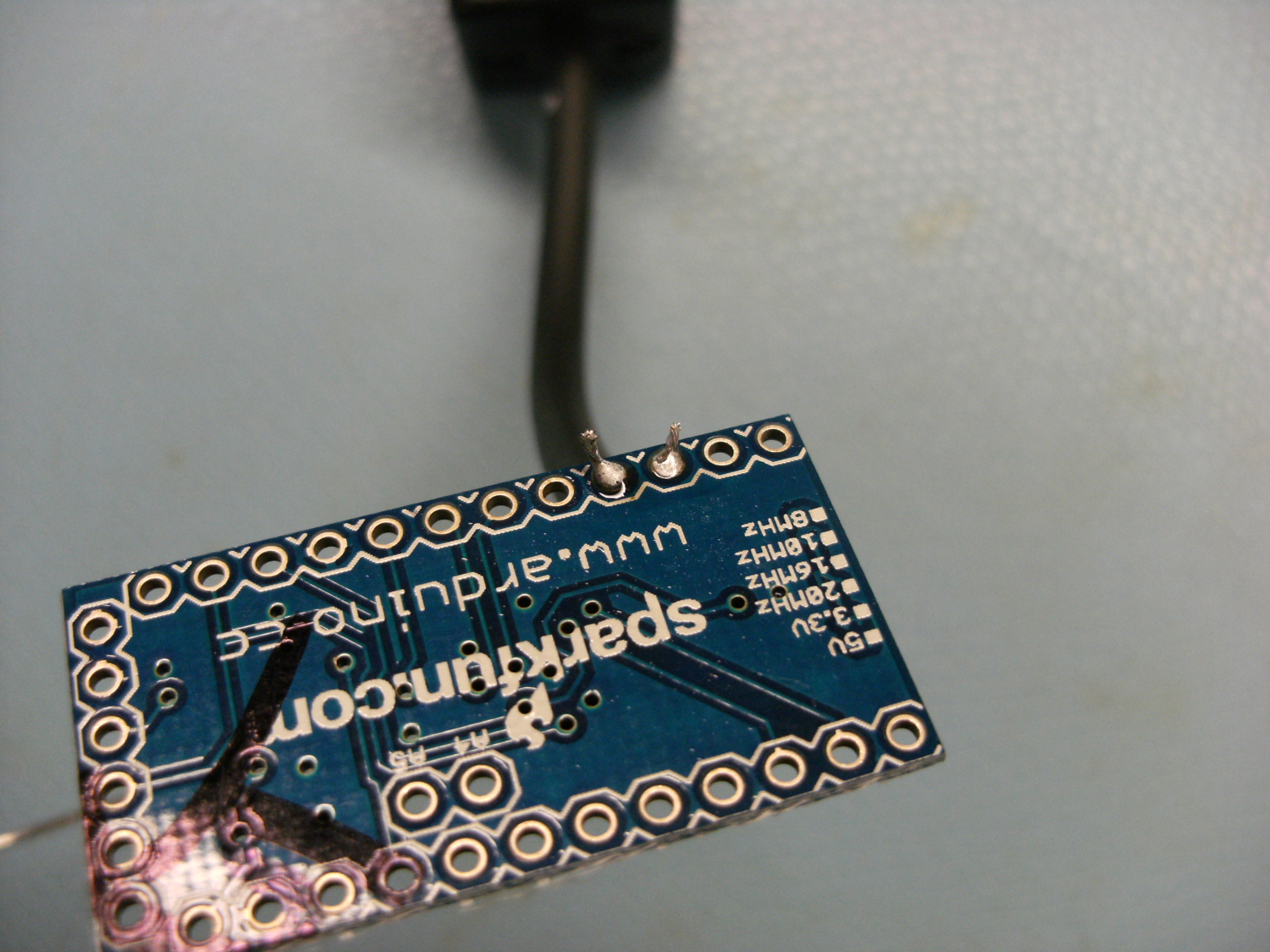
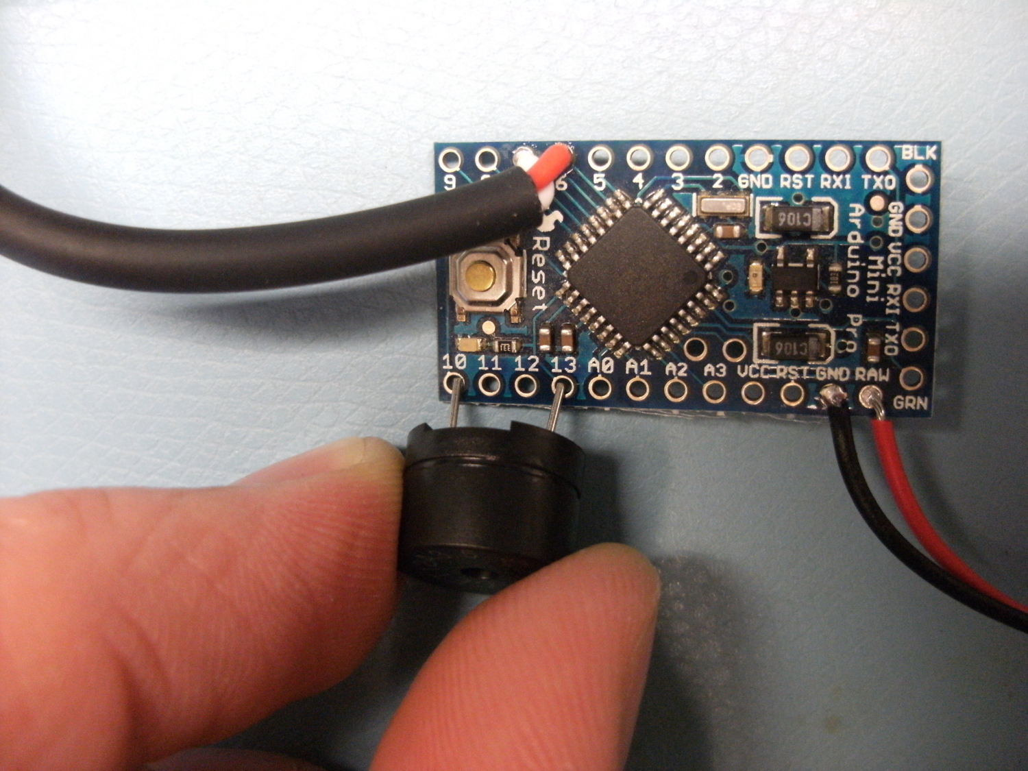
Solder to pins 6 and 7 on the Arduino Pro Mini.
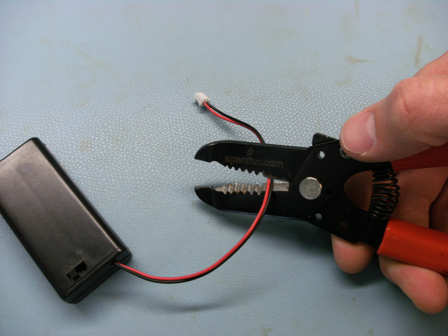
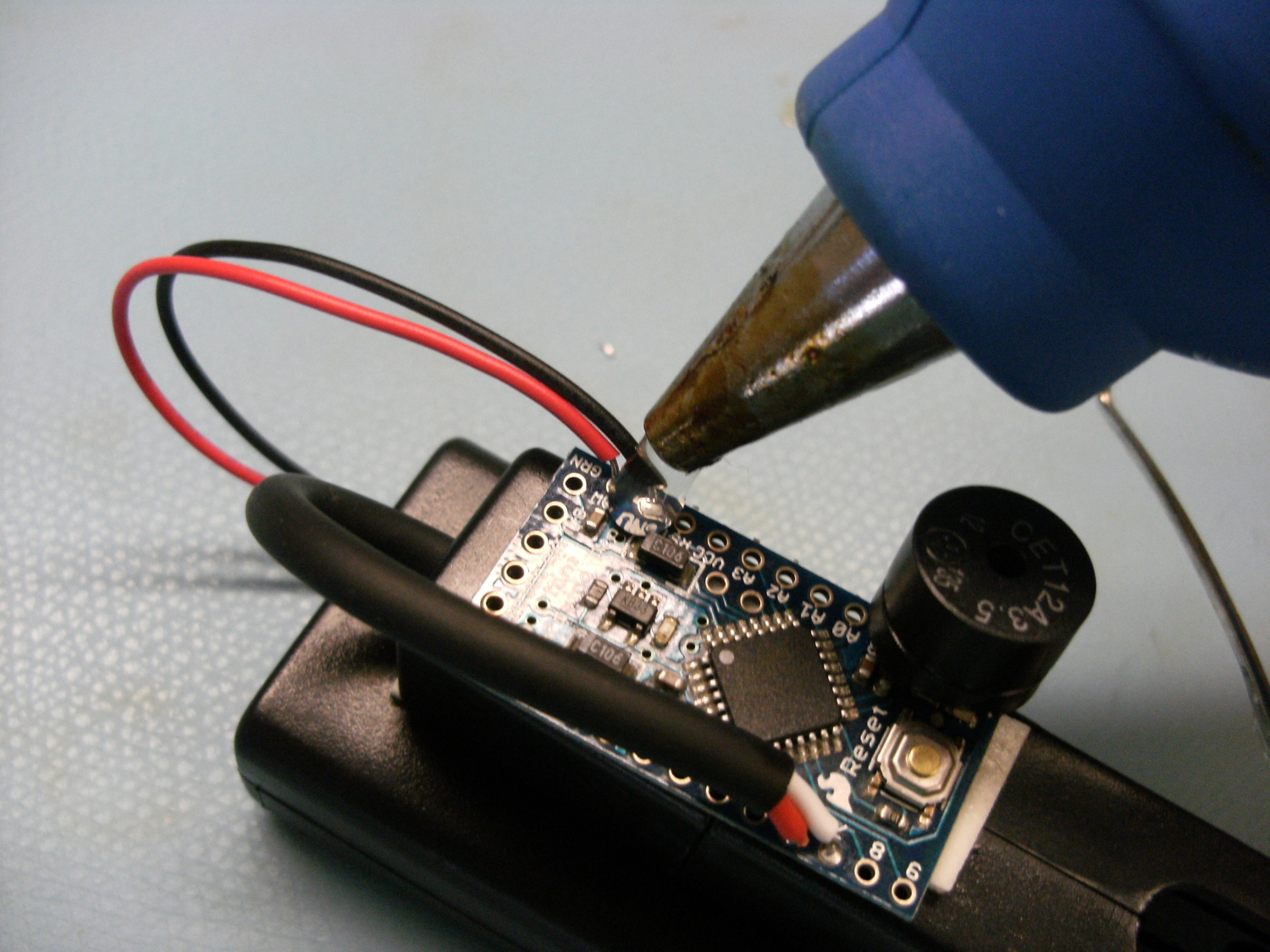
3) Solder Power
*A quick note* Wait until you're done soldering to put the batteries in place. It's always a good idea to do soldering without any power involved. You don't want to accidentally short out your batteries while soldering.
Cut and strip the two wires off of the battery holder.
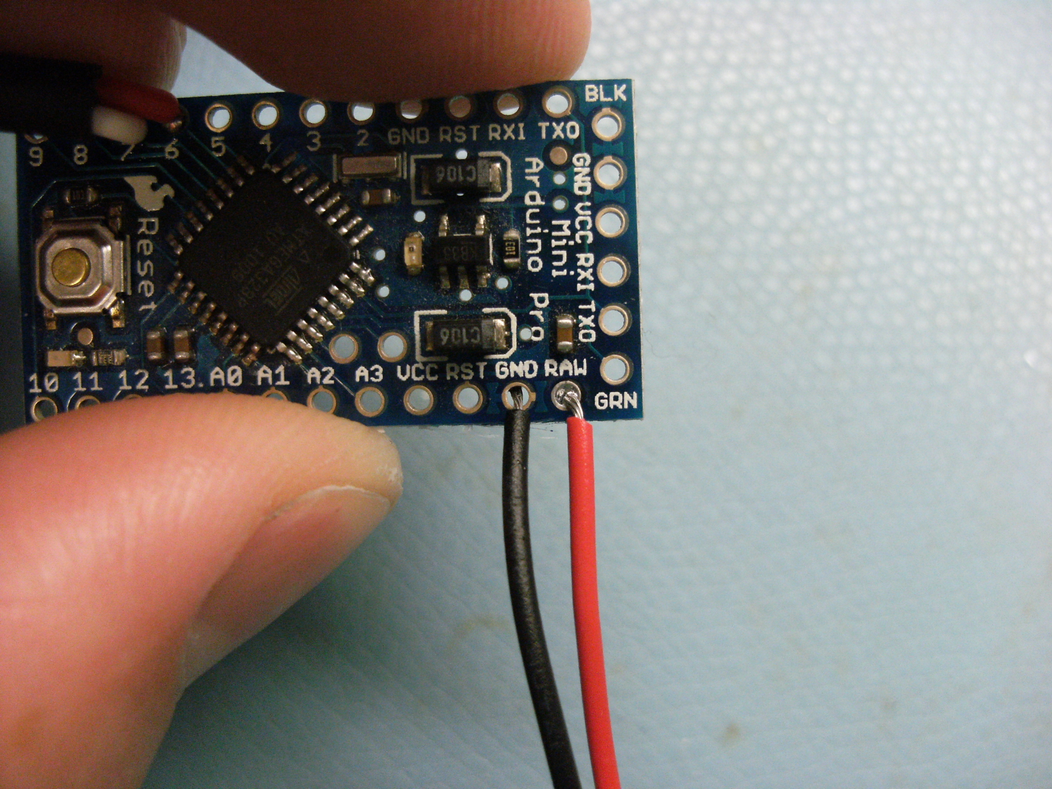
The red wire goes into "RAW"
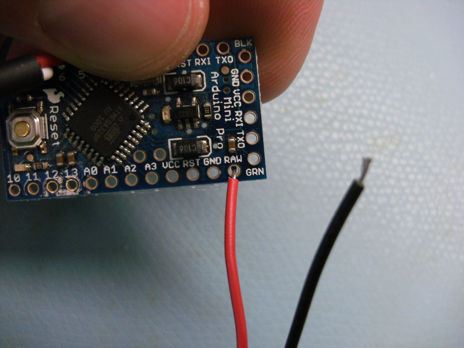
The black wire goes into "GND"
4) The Buzzer (optional)
Solder the Buzzer to pins 10 and 13. You'll notice that the distance of these two header holes is just about right for the buzzer. This is why I chose 'em! The polarity for this does not matter. It will make a buzz either way.

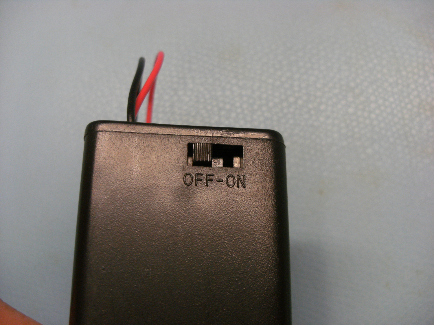
5) Batteries
Now that you're done soldering, it is safe(r) to plug in your batteries. Depending on how you program your pro mini, you may or may not need to turn it on.
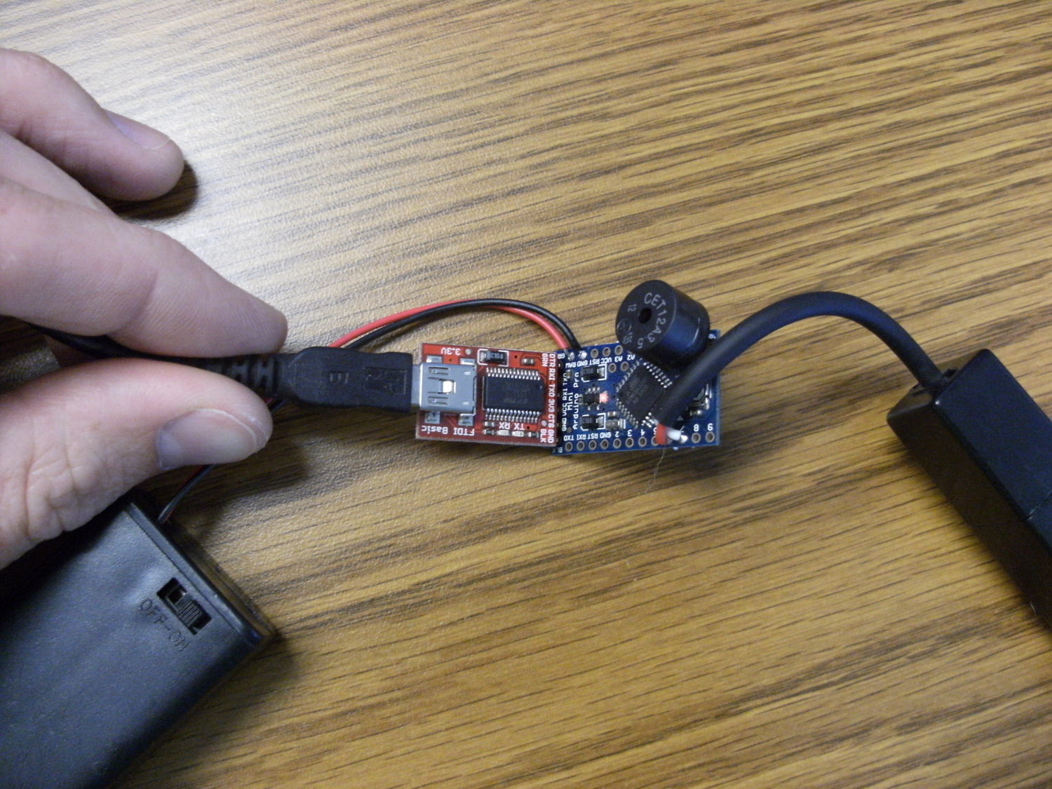
6) Program
Click HERE to download the code. You will also need to download the Arduino Software, if you haven't already.
For more help on programming, please see this tutorial. You can also learn a ton straight from the source here.
This code will simply toggle the "tweezer lines", but it will also play a melody when you first turn it on and sound an alarm when you've left them on for over an hour. If you'd like to change the alarm time, try lowering or raising the number in alarm if statement:
// FAST SWITCHING of the tweezer lines (pins D6 and D7)
// Set the tweezer probe in one direction (HIGH/LOW) to turn on an LED.
// If LED "+" side is touching tweezer probe D6, and LED "-" is touching tweezer probe D7, it will light up.
digitalWrite(6, HIGH); // write tweezer probe D6 HIGH.
digitalWrite(7, LOW); // write tweezer probe D7 LOW.
// Set the tweezer probe in the oposite direction (LOW/HIGH), to turn on LEDs in oposite polarity.
digitalWrite(6, LOW); // write tweezer probe D6 LOW.
digitalWrite(7, HIGH); // write tweezer probe D6 HIGH.
// ALARM feature
// Check to see how long the arduino has been running
time = millis(); // millis() will return an unsigned long integer that increases as time goes on.
// It will tell us how long the arduino has been running since it was furst turned on.
// Decide if alarm should sound
if(time > 3600000) // if it's been over 1 hour (3600000), start alarming.
{
for(int i = 0; i<7;i++)
{
tone(10, notes[i],150);
delay(250);
}
}
You can change the 3600000 to 1800000, if you'd like it to alarm after 30 minutes.
7) Tape it together.
First, clean off your solder joints with some rubbing alcohol. Even a quick wipe with a tissue or paper towel will do just fine to clean up your board.
Using some strips of double-sided sticky tape, attach your pro mini and battery holder to the tweezers.
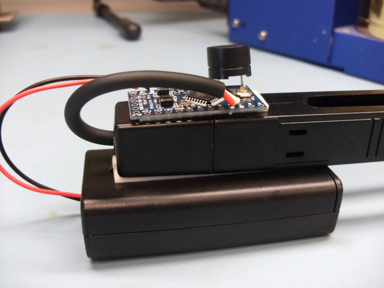
Make sure to keep the battery ON/FF switch accessible.
It's also not a bad idea to keep the programming lines accessible. Sometime down the road, you may want to tweak the code a bit - maybe add your own melody!

For gear that's going to be handled a ton, I always like to add a bit of hot glue to each wire solder connection. This acts like a strain relief on the connection and usually helps it live a little longer.
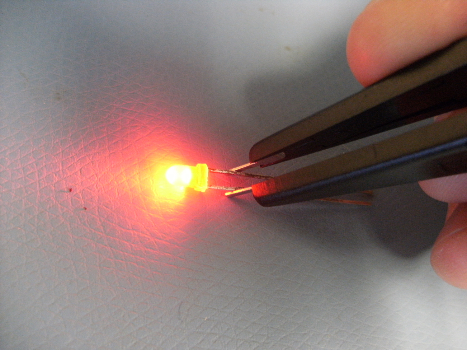
8) Light up some LEDs!!
Congratulations, you have completed your very own set of fast-switching tweezers! Go ahead an light up any bare LED you like. And don't worry about polarity :)
Will shorting the tweezers destroy the microcontroller or is there inherent protection in the 328p?
That's a good point. The ATMega does have some protection on it's IOs, but it's never a good idea to just max out the current on any leg (I believe it's at about 50 mA). It would be a good idea to put a limiting resistor in series with one of the legs. I suppose a 200 ohm aught to do the trick. But for what it's worth, we've had them in production for a few months now and they haven't died yet. I'm trusting that our techs are not shorting the tweezers very often, if at all. Thanks AtWrk for the good question!
I see one issue with the code. The tweezers stay in one state a lot longer than they do in the other. As a result if you have the tweezers connected one the LED will light brighter than the other way (you might not even see the led light at all unless you reverse the connection). The code sets the tweezers to one polarity at the top of the code, then switches it back at once. It then goes through a test of the timer, and returns to the main loop before getting back to the top of the loop() function. There could be a 2:1 or 3:1 time difference between on states. You might want to put a few nops' in the middle of the polarity switch to even things out.
Edit - The sense resistor was not necessary. It seems to work fine with the ADC pin connected directly to the test pin
I took on some of the comments and came up with a working breadboard prototype that uses an ATTINY85 and lights an LED on the probe tip that is in contact with the anode. I also timed the code so the LED under test lights evenly regardless which way round it is in the tweezers. I used PB2 and PB4 as the switching outputs to test the LED under evaluation, PB3 to sense the voltage on PB2, and PB0 and PB1 to drive the polarity indicating LED's. With a little logic and careful setting of the sense voltage break points, the code can tell which probe tip is connected to the anode and light the appropriate indicator. The code uses analog read to determine the system voltage each time it is booted up and calculates break points based on the current voltage. This is a simplistic percentage calculation based on some emperical testing of LED's I had laying around in an attempt to account for varying battery voltage. It would probably make more sense to calculate the ranges based on expected voltage drops across a range of LED's and the sense resistor for different voltages that might be seen, e.g. from a discharging battery. I plan to use a boost regulator and power it from a 1.5V cell so it shouldn't change once it is dialed in.
This is a very simple circuit needing only the uC and power to work as per the original post and a current limiting resitor (optional) and a couple of indicator LED's to add the polarity indicating function.
I have tried it on 3mm and 5mm TH LEDs in red, green, blue, white, yellow, IR, UV and smd green and blue and it works with them all. They are all run-of-the-mill LED's so it may not work with some others.
I have made test probe tweezers before by etching copper clad boards and screwing them to a plastic insulator. I plan to build another set with the circuit etched into the tweezer arms and use all smd components which I already have. The cost is a few bucks for the parts. I wish I had ordered some of the cool colored FR-4 copper clad last time I bought material. It would be perfect for this.
Thanks Pete for posting the project. Here is my code.
Throwing a microcontroller dev board at a problem like this seems like overkill. I've got one of these LED Testers and it works great. And you don't need to worry about leaving the power on.
The flip side is that (barring the slightly overkill arduino pro mini), all of this is the sort of jellybean crud that tinkerers tend to have cluttering up their desks anyway.
Interesting tutorial, but I thought if you sourced power to an LED the wrong way it would blow it out. Is it a "trick" of the 'fast switching' aspect?
Also, when learning how to do simple LED circuits I found you can do switching with a couple 2N3904 transistors, would that work? Save about $15 on the Arduino, but lose the cool alarm feature...
I may have to build one of these, just for the 'neat' factor of it! Thanks!
Nah, LEDs are diodes - if you source too much in reverse it'll break down eventually, but not with the 3v as provided. Look up "charlieplexing" for some interesting tricks this feature makes possible.
Now the neat thing, and I've seen it in my designs so I know it works is that rapidly switching a LED on and off like this somehow seems to significantly lower the Vf requirement. I haven't scoped it up to see if the actual voltage spikes higher than the source through some mechanism. I had RGB LEDs charlieplexing easily (if faintly) as low as 2.1v, while the spec sheet swore up and down that the blue die wouldn't even light up below about 2.8v.
I'm considering doing this with an ATtiny and some makeshift tweezer probes because I'm a cheap bastard and I have the parts laying around.
If you use one of the real tiny ATtiny packages, or even a 6 pin PIC in smt you could fit the micro into the tweezers along with two hearing aid batteries.
Yeah, I almost wish I had a SOIC tiny85, but even still the PDIP would tuck in nicely with a CR2032 at the apex of the tweezers. Put it into deep sleep mode after a few minutes (1.8uA!) and put a pin change interrupt on the tweezer pins, it could be reasonably self contained and long lived.
I commented on this in the news post that covered this tutorial ( http://www.sparkfun.com/news/926 ) and will just add a bit here:
It would be nice if there were actually a polarity indication so that not only does it not matter which way around you have the leads, it'll tell you whether the positive lead is at the anode, or at the cathode.
It addition, the polarity detection code can then stop the switching and hold that polarity, for testing blinking and RGB-program LEDs. They may also be fine with a high enough switching frequency, though.
That same code could be used to deal with bipolar LEDs (which would be forward based in either direction, simply emitting different colors) by changing to a lower switching frequency.