
Mono Audio Amplifier Quickstart Guide
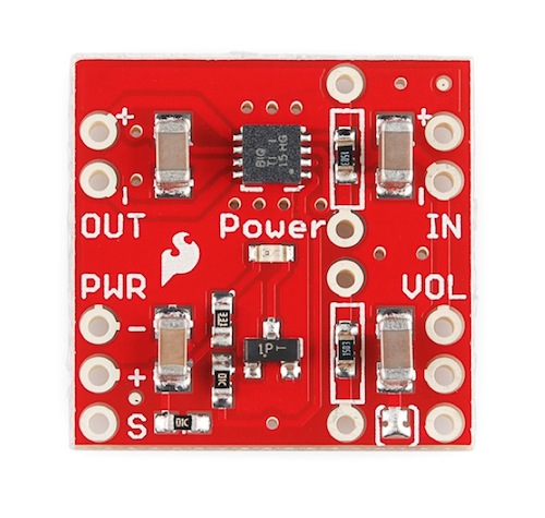
This tiny audio amplifier is based on the Texas Instruments TPA2005D1. It can drive an 8-Ohm speaker at up to 1.4 Watts; it won't shake a stadium, but it will provide plenty of volume for your audio projects.
Quickstart
- Connect your line-level audio input to the IN + and - header.
- Connect your speaker to the OUT + and - header.
- Connect 2.5V to 5.5V to the PWR + and - header. (Don't connect anything to the S (shutdown) pin yet.)
Send some audio to the input, and you should hear it on the speaker! If the sound is not loud enough, if you hear buzzing, or if you'd like to add a volume control, read on.
How it works
Traditional audio amplifiers use power transistors to multiply an analog input by a certain gain to produce an analog output. This produces great sound, but the transistors must operate in the intermediate region between on and off. Transistors operate most efficiently when they're fully on or off, and waste a lot of energy as heat when they're run in between.
The class-D amplifier is radically different. At any moment its output transistors are either fully on or fully off, which is very efficient. But this means that the output isn't true audio, it's a digital PWM-like waveform which is mostly on (VCC) for high output values, and mostly off (GND) for low output values.
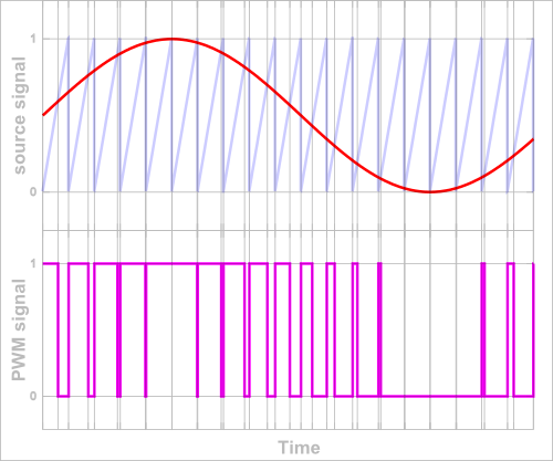
This PWM signal is clocked at 250kHz, which is much higher than the audio frequencies being encoded (< 20kHz). Because speakers are mechanical devices that can only respond to audio frequencies, the PWM signal is effectively filtered back into the original audio frequencies by the speaker coil itself. All you hear is the music!
Check out the TPA2005D1 datasheet if you'd like to know more about this amplifier.
To use the amplifier
Connect your input source to the IN + and - header. Because the inputs are differential, it technically doesn't matter which direction you connect them, but if one of your inputs is ground or shield, connect that line to the - terminal. (See the Tips below if you're having problems with hum).
Connect your speaker to the OUT + and - header. If you're using one speaker the polarity doesn't matter, but if you'll be using multiple speakers, ensure that you wire them all the same way to avoid phase problems. The speaker can be 4 or 8 Ohms. The maximum output of the amplifier is 1.4 Watts into 8 Ohms. You can drive smaller-wattage speakers with this amplifier, but you should be careful not to turn up the volume too high to avoid damaging the speaker. You can also drive speakers larger than 1.4W at reduced volume. In general, larger speakers will sound much better than smaller speakers; we've had great luck with old automotive speakers.
Connect a power source to the + and - pins. The power source can be from 2.5V to 5.5V, and should be able to source at least 280 milliamps if you want maximum volume. The red LED will illuminate when the board is powered up.
Apply an audio signal to the input, and you should be able to hear it on the speaker. To change the volume, either change the volume of the signal at its source, or add a volume-control potentiometer to the board (instructions below).
Adding a volume control knob
If you wish, you can easily add a 10K volume control potentiometer to this board. The volume control will let you control the volume by reducing the input signal from 100% to 0%. Note that this will not make the amplifier any louder - if you'd like to do that, see changing the gain resistors below. Here's how to add a volume control potentiometer:
Remove the solder from jumper SJ1. This is the small blob of solder within the white brackets on the bottom right of the board. The easiest way to do this is to apply solder wick to the jumper, and heat it with your soldering iron. When you're done, ensure that the two sides are electrically separated from each other.
Now, connect your 10K potentiometer to the three pads on the lower right of the board. The bottom of the board has silkscreen showing the proper connections. You can solder a trimpot with 0.1"-spacing on the pins (such as COM-09806) directly to the board, or you can use wires to connect the board to a larger potentiometer in a chassis, etc.
Note: Potentiometers come in two styles: "linear taper" and "audio (or logarithmic) taper". Audio taper potentiometers have a logarithmic bias that give a more natural feel in audio volume control applications like this one, but linear taper will also work just fine.
How to use the shutdown pin
The SDN* input can be used to turn off the amplifier to save power when it's not being used. When SDN* is disconnected, or connected to a high logic signal (> 2V), the amplifier will function normally. When the SDN* pin is connected to ground or a low logic signal (< 0.8V), the amplifier and LED will turn off. You can use this feature to save power in battery-operated projects.
Changing the gain resistors
The amplifier chip uses two fixed resistors to set the gain, which is how much the input signal will be amplified. On this board, we're using 150K resistors as recommended by the datasheet, for a gain of 2. If you would like the output to be louder, you can install smaller resistors.
The gain equation for this amplifier is 2 * (150K / R). So if you use 100K resistors the gain would be 3, for 50K resistors the gain would be 6, etc. The datasheet states that the smallest value you should use is 15K for a gain of 20, but we've gone down to 3K (gain = 100) with fair results.
The amplifier board has two positions to add your own through-hole resistors. These are within the white rectangles on the top of the board. You do not need to remove the existing surface-mount resistors, just put your through-hole resistors over the top of them. (Leaving the SMD resistors in parallel with the new resistors will slightly reduce the total resistor value, but this is generally not a problem).
For best results, the two gain resistors should be as closely matched as possible. If you have a bag of identical resistors, you might measure them all with a multimeter and pick the two that have the closest resistance.
Tips
The amplifier's output is only designed to be connected to something with a coil (a speaker or magnetic transducer). Since the output is not a true analog signal, you shouldn't expect to use this board as a preamplifier, etc.
The differential inputs of this board are safe to connect directly to floating-ground audio signals such as from the MP3 Shield and MP3 Trigger.
If your audio source and amplifier have different AC power supplies (such as audio coming from a desktop computer), you may hear a loud hum in the output. To fix this, connect a jumper wire between the - side of the audio input and the power supply ground (PWR - header).
Because the amplifier outputs a 250Khz PWM-like signal, it could potentially radiate interference to nearby sensitive circuitry. For this reason, keep the wires between the amplifier and speaker as short as possible.
Questions?
If you have any questions or problems, let us know at techsupport@sparkfun.com and we'll do our best to help you out. We'd also like to hear about the cool projects you're building with our parts!
Have fun!
- Your friends at SparkFun.
I want to use a smartphone to both power the amp and provide audio. The amp powers up just fine (led is on), and when I connect a speaker to the audio in pins that I wired the headphone jack to, I get sound. I hear nothing on the out pins though but do see some impedance fluctuations. I am not very experienced, so I might be overlooking something basic here, does any of you have any ideas what is going on and how to fix this? Thank you for any help.
Hello, I want to use a stereo USB DAC. Should I connect "R and L" to IN + and ground to IN - Or R on the IN + and ground on the IN -
thank you in advance for your help
Can I connect the IN+ to GND (as shown in Figure 34 of TPA2005D1 datasheet) and IN- to an Arduino's PWM output?
I want to generate the signal via an output pin on an Arduino. The Tone function in the Arduino library or something similar would be used. Essentially, the output is a square wave at the desired frequency. The piezo devices don't have enough volume, so this is an experiment to see if the combination of the 8 ohm surface transducer with this amplifier makes the sound audible over ambient noise. But I am decades from my audio experience (such as it was) and "line level" conveys nothing to me about what the voltage levels should be. Any advice as to how to use this to amplify the output from the Arduino? Note that concepts like THD are irrelevant here. The idea is to be able to generate sequences of tones to convey the happiness or lack thereof of a given piece of equipment. Happiness would be a short beep about every minute; degrees of unhappiness are indicated by different combinations of beeps (lower pitch, or two-tone sequences, or a descending glissando [battery low, in case you were wondering]), as appropriate, and the interval between the sequences indicates the degree of unhappiness, e.g. 10 repeats per minute means that something Really Bad is imminent. If the square wave gets distorted and looks sinish (or cosinish), sawtooth, or other weird shape, that just doesn't matter. What I need are different frequencies, and volume. The surface transducer would be mounted on the inside of the case containing the device. The nature of its environment is not user-friendly to electronics (read: very wet) so there are no openings in the hermetically-sealed case. This rules out internal or external speakers.
I use this with a AAA battery as a small stand-alone audio amplifier for an earpiece. The efficiency is unbelievable. To get the unit to 3.3V I use the following booster:
http://www.ebay.com/itm/DC-1V-1-5V-3V-to-3-3V-Step-UP-Power-Converter-Voltage-Module-STM32-FPGA-CPLD-DSP-/271308401258?hash=item3f2b3daa6a:g:2vcAAOSwZtJW-~Tn
This little booster is super efficient as well. Bottom line is that this combination, even with such a small battery, seems to have as much run time as with a 9V battery would using an LM386.
Not sure if there are right and left hand versions of pots?? but I've installed a 10k pot as described for volume control, which works, except it's backwards (turning clockwise decreases the volume). This is pretty frustrating. Is there anything I can do?
Yep, well kind of, swap the outside pins. Right now if you turn the pot completely counter clockwise the wiper is connected to one end. You want it connected to the other end. I believe moving the pot to the other side of the board should do that if the pot is soldered to the board (if not then it should be even easier)
Does this work out of the box with MP3 shield, or do we need to pay attention to something in particular. I believe DC offset needs to be removed in shield, but amp circuit already has the capacitors for the same. Right ?
This particular amplifier works very well with the MP3 Shield. It has fully differential inputs (both input leads are "floating"; neither one is tied to ground) so it doesn't have the "virtual ground short" problem that the MP3 Shield has with amplifiers where one input is tied to ground.
It seems to me a series inductor then a shunt capacitor right near the PCB could suppress that RF interference. Could anybody suggest particular values? Is 10uH & 1uF enough?
answered my own question... The datasheet shows a filter in fig42 with 33uH & 1uF on each output lead. Optional of course. Sheet says it may improve battery life a bit. By less than factor of 2 I guess.
Wow, I got the little mono audio amplifier breakout board today ... Can't they make it smaller? There seems to be wasted space. Maybe make these things 20% smaller? At least I can fit it into a project, but if it was smaller I think it would be easier to use in more projects. I like designing tiny robots that talk, sing and dance.
RoboToons Robot Theater - I've Fallen and I Can't Get Up! https://www.youtube.com/watch?v=3gV8DYyoIss
Meet Baby BillyBot http://brainless.org/OPEC/PICAXE/IMG_3383-20150323-MeetBabyBillyBot.JPG
Hi, Why not use a class "A/B" type chip like the LM4991 or LM4871 for better audio quality and more volume? Is there that much energy savings?
I wish the dimensions were published in the sample images like other components. I also wish everything was in mm to make designing for these parts easier ... I hate English fractions and although born in the USA, I've been using Metric for many years because it's so much easier.
Yes, there is that much energy savings! When using an AB amplifier, you're actually putting more power into heat than into the speaker (see the power dissipation graphs in the AB datasheet). The class D amplifier runs cold under the same conditions, meaning your battery will last twice as long. The tradeoff is that the THD will be lower (higher audio quality) for an AB amplifier, but unless you need absolute top-quality audio (and have the power to support it), the class D chips are a pretty good choice.
Sorry about a lack of ruler in the pictures, I'll see if I can't get it into the queue for a reshoot. Also sorry about the units; as engineers we're disappointed that we still haven't switched to SI (and likely won't in the foreseeable future).
Also, if you're looking for a more powerful AB amplifier, check out our Amplifier Kit.
Seems the basic resistors wasn't enough to amplify the pickup output of my acoustic guitar to another transducer placed on the inside of it. Basically planning to use it as a budget amp run on battery.
EDIT: works much better with two 5.1k resistors. But the 1W transducer I had was a bit to small. But it gave the reverb-echo-effect I was looking for. Great circuit!
EDIT2: After some evaluation I can't say I notice any real difference. It works when plugged in to a computer. But I barely get any effect using a pickup. Thinking I might need a preamp for the pickup.
EDIT3: Duh. Just realized I've been driving it with 2x AAA which lands me at 2.4V. facepalm
Can I use this to convert an (analog) sin wave from arduino (PWM) into amplified analog output such that a piezo actuator will follow it. The piezo amplifier takes 0-6volts analog signal.
Not very well. The arduino's PWM frequency is only 490Hz.
Is there any way to use this to amp the sound coming from a 3.5mm jack on a phone? I wanted to amp the output to power the small transducers.
Would this work with the large surface transducer? I want make some awesome pranks.
Yes, it works great with the big transducer!
Question on input for this item
Can I hook this input directly to a pin & ground of a BASIC STAMP or Arduino to use with the Freq generator that normally powers a peizo?
Some of my adult students are hard-of-hearing and this would be great for them.
Thanks.
Yes, its going to be loud and clipping the signal but they are square waves and clipping really doesn't matter.
I've got this hooked up to a 50 W speaker (it's all I have available) using the 10K pot for volume control. At about 3/4 of the max volume, I begin to get some clipping with my audio. Up until then it sounds great. Any way to fix this?
could you use two of these in parallel to run a 8ohm 2.8W speaker?
No. The outputs would fight with each other. With a good-sized speaker it can throw a lot of volume, so you might want to try one and see what you think.
ok, but wouldn't driving a 8ohm 2.8W speaker with this be pointless since it can only go up to 1.4W? or am i missing something?
A speaker's wattage is the maximum power it will take before the coil burns out. If you're not putting 2.8W into it you won't hit its "maximum volume", but in practice "maximum volume" is likely much too distorted / loud for most purposes.
We've found that the larger (physically) the speaker is, the better it sounds, no matter what the wattage is. We use this amp with 6" 20W speakers with surprisingly loud and great sounding output.
I would think so. One amp for left and one for right. You'll have to share the the power source for each channel. If you do volume control then you would need to have a common trim pot or separate pots for the left and right. Should be pretty straightforward to make the circuit. I just finished wiring up a speaker from an old clock radio. I boosted the gain with a pair of 4.7 K resistors. Pretty nice results.
I second the question above. Could you put a stereo pot before the input and then make to of these to create a stereo system?
Could I use two of these to make a stereo output?