
Picture Frame Tetris
As Paul (a SparkFun employee) says, 'that's a whole lotta tetris'.
We string together 15 buttons pads, a bunch of ATmega8s, program in some rules to Tetris, and out comes a wall-sized interactive Tetris game.
You gotta thank the team of people that made this thing work:
- Bill Barker - The cable guy
- Tyler Talmage - "As long as I don't have to solder another RGB LED"
- Casey Haskell - Tool path and mechanical design
- Josh Nathan - Plastic and mechanical fabrication
- Nathan Seidle - Hardware, coder, and idea guy
- Adrian Moorhouse - Coder and proto assembly
- Joel Bartlett - Pad builder
- Matt Bolton - Assembly Overlord
- Anndrea Boe - Fantastic photos of a very awkward subject
- David Carne - Creating some great graphic demos
It took a few people a few man hours to pull this thing off. I hope you enjoy!
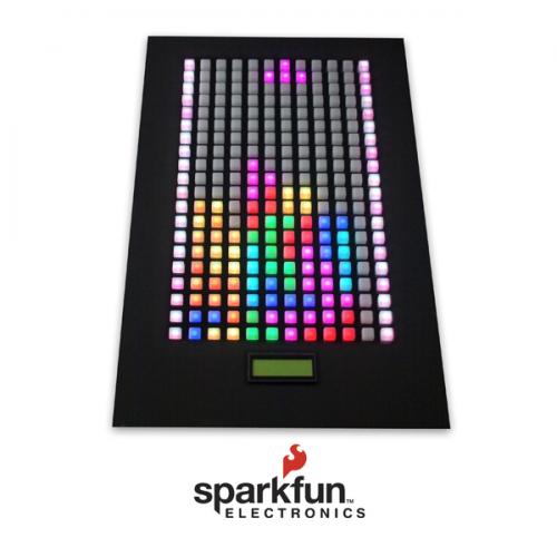
What is this thing? It's the game of Tetris but played on a device that is composed of 240 buttons. So if you want to move the Tetris block right/left, you simply touch a button left or right of the current piece. To rotate a block you touch a button in one of the top two rows. And to drop a block you touch the bottom row. It's a hands on Tetris game! Watch:
A few 'wow' numbers:
- 16 microcontrollers
- Total of 256 MIPS
- 720 LEDs
- 1.5A current draw
- 1300 lines of code
- 28800 bits being updated per second
- 9 people
- ? man hours
For those of you that want the nitty gritty technical details, here are the schematics and firmware:
- Button Pad Controller Schematic
- Button Pad Firmware
- Main Controller Schematic
- Main Controller Firmware
We had seen the Monome project at the 2006 Maker Faire and it intrigued us. The idea that the button color could interact with the person touching the button was a great idea. It's like the rubberized buttons on your TV remote, but with an LED behind the button. So when you touch a certain button, the LEDs around (or in) that button change. The monome project only had room for a 3mm diameter LED. We wanted more! So we designed a 4x4 button pad that could utilize a 5mm diameter LED, and then we could go crazy with our RGB LEDs!
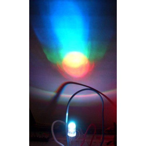
Red, Greed, and Blue (RGB) LEDs built into one 5mm package.
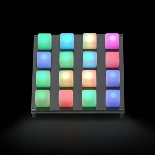
The SparkFun 4x4 button pad
If you're into embedded electronics, you may start to see what monumental task we thought ourselves into. The standard Tetris board is 10x20 cells and each cell needs to light up 1 of 7 different block colors. Our button pads are 4x4, multiply by 15, and you've got an array of 12x20 buttons. You stick a RGB LED behind each button and you have the potential to light any button, any color (you just mix different intensities of Red, Green, and Blue and you'll get any color).
The problem arises in the mass of numbers:
-
12x20 = 240 cells
-
240 cells * 3(RGB) = 720 individual LED channels
-
Each channel needs to be Pulse-Width-Modulated (PWM) faster than ~30Hz so the human eye doesn't notice the flicker
-
We also need to scan each button to see if it's being pressed!
-
Some sort of processor needs to update all 720 LEDs, run the rules of Tetris, and react to any button presses
Obviously we need to breakup this project into pieces. So we designed a PCB that would incorporate the 4x4 button pad, RGB LEDs, and the needed drivers and an ATmega8 to run the show. The idea was that a static color data frame would passed to each of the 15 controller boards and those 15 boards would dutifully display what they were supposed to. The 15 pads would also report back any buttons being depressed. Sounds great on paper, right?
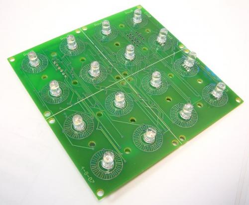
The front of the Button Pad Controller
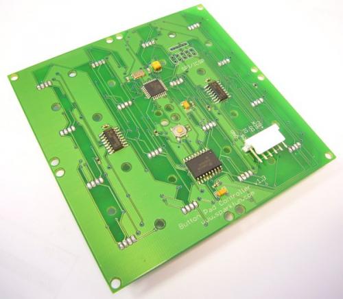
The back of the Button Pad Controller
Here you see the ATmega8 running at 16MHz with two shift register and a ULN2003 sink driver. The board has a 6-pin connector for the SPI interface (5V, GND, MISO, MOSI, SCK, CS).
These basic driver/sink circuits were designed for another product, the serial backpack for the Tri-Color LED Matrix:
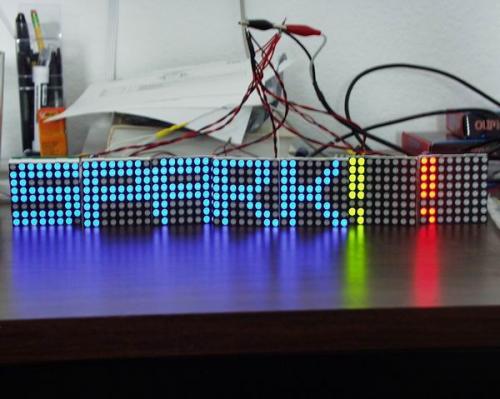
7 of the Tri-Color LED matrices wired up
Because the LED matrices shown aboard were 8x8 (64 LEDs) we could reduce the shift registers on the button pad controller (16 LEDs) by one shift register IC, but we also needed to monitor button presses. It's beautiful how the final button pad schematic came out. We were able to use the extra 4 pins on the 2nd shift register to use in the button scanning process.
The idea was to have one master that would send color data to each of the 15 button boards. The button boards would have no idea about the game of Tetris or where they were in the Tetris board - they would only be responsible for continuously updating (PWM) their local LEDs and giving button press data back to the main controller. The main controller would be in charge of creating blocks, running rules, responding to button presses, and would only have to refresh the entire board (15 pads) a couple times a second and the button boards would do the rest.
Each time the main controller sent frame data to the button boards, the button boards would also respond to any button presses. The master would receive these button presses, and because the master knew which pad it was talking to, it could correctly load that button press into a large array that represented the Tetris game.
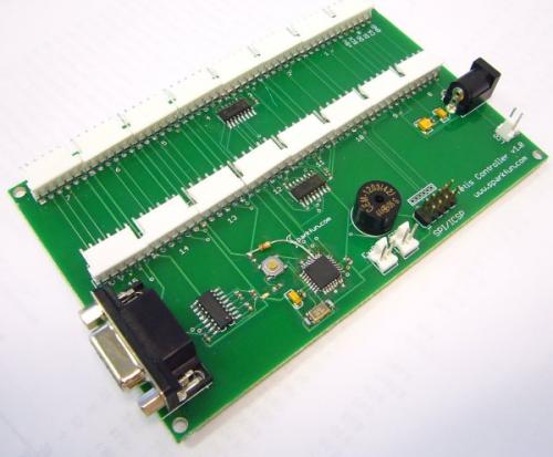
The Main Controller Board
The main controller board (schematic) was responsible for the rules and for sending all the color data to the 15 individual button boards. We also rigged up a 20x4 SerLCD so that we could display Time, Score, Lines, stuff like that. There's a buzzer for annoyance factor and RS232 for debugging. There are 16 channels built into this board just for aesthetics (the pin was available on the shift register). We only ever use 15 channels. Everyone plays together on an SPI bus. All 15 button boards have 5 identical wires (5V, GND, MISO, MOSI, SCK) so we can string together almost all the pins together. The only difference is that we need 15 independent Chip Select (CS) pins. That way, the master controller can select one out of the 15 button boards and give it a data update, while the other 14 boards ignore what's coming down the SPI bus.
How does the master controller access 15 different CS lines? By using two shift register of course! Here is the schematic for the Tetris controller board.
The board assumes a *regulated* 5V input. Why don't we throw a voltage regulator on there? Because the master board powers all the other button boards. This gets power hungry really fast:
-
Each RGB channel has the potential to draw 20mA
-
720 channels * 20mA = 14.4A
Holy shnikies! That's a lot of current! There is no way you'd want to try to regulate that much current on a little board like that. It's better to provide the board directly with a nice, juicy 5V regulated power supply. Luckily, with a little testing, it became apparent with the PWM, each LED draws about 2mA. With the entire board running fully illuminated, the system draws about 1.5A. This is smaller, but still not trivial. Our switch mode power supplies that output 5V would work, but they max out at 1A. You can always buy a switching power supply from someone like Digikey, but these can be really expensive and often have very limited availability. Instead, we hacked up a computer PSU. We had to the same thing for the 12' GPS Wall Clock (it used 12V at 2A), so we built another one for the Tetris board (using the 5V rail instead). If you want more information about this - google it (or email us and we'll post it). There's some good tutorials online about modifying a $20 computer PSU to get the 3.3V, 5V, 12V, and -12V rails. Our $20 460Watt PSU can push 30A at 5V. Wow! That's a lot of power, Scotty.
So we've got the main controller board powering all 15 button boards. The main board has access to all 15 unique CS lines. Now we've just got to wire everything up and write some code.
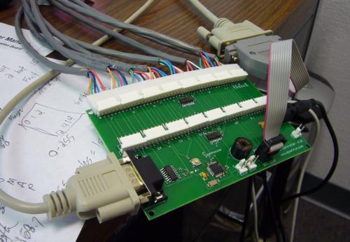
The controller board under test
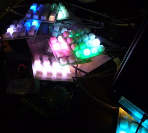
A few button pads running initial code
Watch the video!
Another demo of droplets and LED control
There was a lot of code to be written! The data frame protocol, the LED PWMing, the Tetris rules, the button response routines, even block gravity (when a Tetris line goes away, the blocks above drop down and fill the open gaps). It's still amazes me it works. We actually found out that our system speed (16 individual ATmega8s running at 16MHz) was way faster than we originally thought! We actually have to slow down the overall board update rate. We can do a complete board update (send the appropriate color data to all 15 button boards) 100 times a second! This is much faster than the eye can detect and so we can do some really interesting color demonstrations and user interfaces. This is where Monome exceeds! The monome project was originally designed to be controlled by a computer. It's really difficult to program complex math routines into our main controller board to do any fun fractal, wave, spiral, or other neat graphic demonstrations. We obviously need to build another board that has a computer interface!
Once everything was working, the mechanical gurus still needed to figure out a way to package this rats nest.
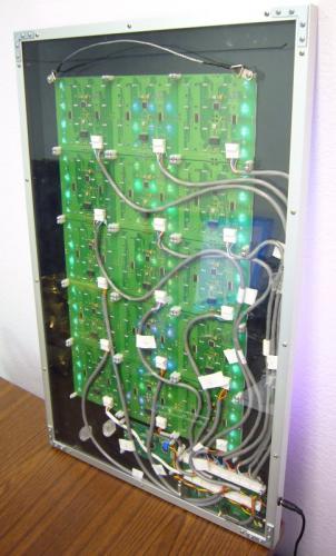
The backside of the Tetris board
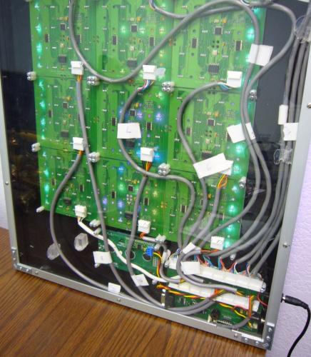
Cables. Lots of cables. And you have to be really creative how you route them so that everything fits. The frame is 1" aluminum. Once you get all the cables in place, inevitably one of the connections breaks then you get to take everything apart and go hunting. In the end, we would have been better off with a split controller design (two controllers, one in each lower corner) to save some cable headaches, but we got it all working!
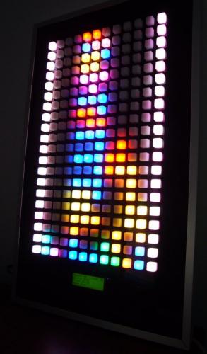
A quick game
It's a hefty picture to hang. At 10lbs, you need a good anchor to hoist the board.
Playing Tetris!
That's it! I hope you enjoyed reading about the Picture Frame Tetris game. Before you ask if we'll sell you one, realize just how much hardware, man hours, and customization this device takes. The monome folks have done well building smaller 8x8 mono-color units. We believe we can build 16x16 button/Tri-color LED boards (not Tetris - just a very wild interface board) for about $1500. If anyone is interested, please email us!
We demoed the Tetris board at Maker Faire 2007. It was a ton of fun. Here are some shots:
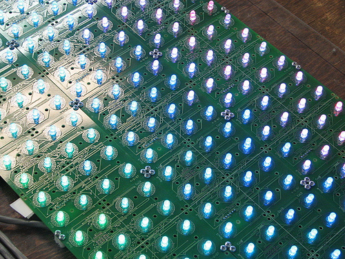
Here is a shot of the internal boards and RGB LEDs doing their thing. From Phillip Torrone's Maker Faire 2007 Flickr
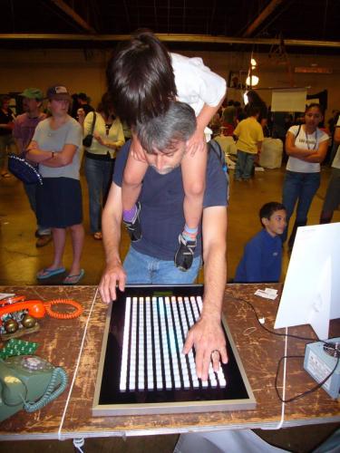
Here is a Maker and her dad at the SparkFun booth. That must have been a fun way to play!
We had a great time at Maker Faire 2007. We hope to see everyone again next year!
Comments 0 comments