
GPS Tracking Comparisons
Introduction
The goal of this tutorial is to show you how to use GPS NMEA data and demonstrate some of the features and hardware one finds in embedded GPS modules/receivers. In addition, I will show how the features and hardware can affect tracking accuracy. This is not a buying guide per se, but it will help you get an idea of the differences, shown in Google Earth, between chipsets, antennas, and update rates for the six SparkFun GPS modules seen below.
I choose modules with different chipsets, antenna/hardware configurations, and update rates in order to get a general idea of the wide variety of features. All modules were left in their default states (except for the SUP500F which I had to configure for 10Hz update rate). The Copernicus and uMini use SMD GPS modules and are assembled by SparkFun. The other four are from outside suppliers.
| GPS Module | Chipset | Antenna | Update Rate |
|---|---|---|---|
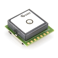
| Copernicus | Trimble Trim Core | ceramic patch | 1Hz |
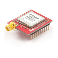
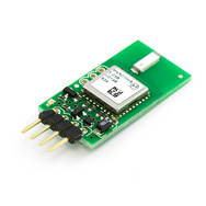
| SUP500F | Venus634 | small ceramic patch | 10Hz |
| MN5010 (uMini) | SiRF Star III | chip | 1Hz |
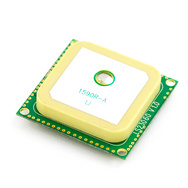
| LS23060 | MediaTek MT3318 | ceramic patch | 5Hz |
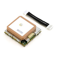
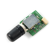
| DS2523T | U-Blox 5 | helical | 4Hz |
| EM-406A | SiRF Star III | ceramic patch |
1Hz
|
Refer to individual product pages and datasheets for the detailed technical information for each module.
Building the tester
Here is the bill of materials (BOM) for testing each GPS module:
- Breadboard Power Supply Stick 3.3/5V
- LiPo Battery Pack 1000mAh/7.2V
- openlog
- uSD 1GB
- jumper wires and headers
The following are some issues that I had to consider when designing the test rig.
GPS modules are radio frequency receivers.
For reliable performance, your GPS module needs to receive good unobstructed signals from the satellite constellation. GPS modules have relatively tiny antennas to receive data from satellites moving at relativistic orbital speeds, over 10,000 miles away, and so they need somewhat of a clear view of the sky. I know this might sound really obvious, but I cannot stress this enough, because...
GPS sensitivity and accuracy is highly dependent on environmental conditions.
Not only does this include physical objects, like trees, earth, and structures, but also includes atmospheric effects, space weather, the overall health of the GPS constellation, and multipath interactions, all of which contribute to constant variability in receiving the GPS signal. To minimize errors due to these environmental effects, I wanted to test and track all six modules at the same time with varying views of the sky.
What I needed was a mobile logger for each GPS module. SparkFun stocks more than enough supplies to accomplish this.

Tracking Setup. Note: The uMini was oriented vertically for the test and is not shown that way in the picture
![]()
Connection Block Diagram
Each GPS module should have its own clean (regulated and decoupled) DC power supply.
The GPS power supply feeds into the antenna power supply on some of the modules, so any excessive noise or unexpected loading on the circuit can affect performance. Attaching a high capacity LiPo battery to a regulated Breadboard Power Supply Stick for the power supply for each module is sufficient.
Next, I capture the data coming out of the GPS module with the openlog.
All that needs to be done is to connect the transmit pin (TX) from the GPS module to the receive (RX) pin on the openlog. The openlog will log anything it sees on that pin, just be sure to configure the baud rate on the openlog to match the baud rate coming out of the GPS module.
A brief word or two on the VBATT pin and the TTFF (time to first fix).
What is the VBATT pin used for? Some embedded GPS modules contain volatile RAM that is used to store the almanac and ephemeris data of the satellites, which is globally updated on a regular basis. Think of the almanac data as a "bus schedule" of when and where each satellite will be in the sky. The ephemeris data contains the errors in the schedule. If your GPS receiver does not have the schedule or the errors of the satellites, it will have to download that information when there are updates. Since the RAM stores this data, the VBATT pin should be powered or connected to some kind of energy supply (i.e. supply voltage, battery, or supercapcitor), so that your GPS module can quickly start-up. If you don't power the RAM, all of the almanac and ephemeris data is lost with each power cycle.
The TTFF (time to first fix) is determined by how quickly the GPS module can access the almanac and ephemeris data. If the module doesn't have any of this data (some modules don't have this data out-of-the-box) the module might take a bit of time to power up. Same goes for if you don't connect power to the VBATT (RAM power) pin, you will lose all of the data upon a power cycle. If the almanac and ephemeris data can be permanently stored in flash, like the SUP500F can, then you should get a really fast TTFF. Some modules, like the EM406, have a supercapacitor attached to the RAM. This means you will get really quick TTFF for only a period of time after you power the module down. Wait too long, the capacitor will discharge and you will lose your information. The reason for the choice in using a supercap over a battery or flash chip, is that it is in expensive, small, and the almanac and ephemeris data needs to be updated regularly anyway, so if your position is changing a great deal over the globe, you don't need to keep all of the same almanac data.
In terms of the TTFF performance for each of these modules, all have similar stated fix times that are under 1 minute, but will differ with environmental conditions and antenna hardware.
Tracking
Download Google Earth to view the KMZ files and zoom around my track in 3D (be sure to turn on 3D buildings). Just click the link and Google Earth should open and zoom to the the SparkFun building.

Overview
For my track, I decided to walk the GPS modules around the SparkFun building, instead of testing them in a car. GPS modules, to an extent, seem to work better the faster they move, so walking the units around the building should create a test condition where the GPS modules will have a greater chance to show errors.

Actual track walked (top is northish).
Here is a brief summary of my track: I turned all of the module's power ON next to a window on the second floor of the SparkFun building. I waited a few minutes, then made my way outside to the north most point of the parking lot, where I waited to make sure all of the modules had a lock before I proceeded south around the building and back to where I started. For more info on the outside track refer to the 2010 Autonmouns Vehicle Course Preview.
What does it mean when the receiver has a lock or a fix?
When the receiver has a lock, you get accurate position (3D) and time data. This is accomplished when the receiver sees at least four satellites in good view. Why four? Well, I'll give you hand waving explanation, but the full explanation is well beyond the scope of this tutorial and most users. For a thorough explanation, there is a two volume text book written on the subject. Here is the first volume, free to view and download. Thanks Dan!
Easy Explanation:
You need 4 satellites for 3D trilateration and 3 for 2D trilateration, no need to consider time [see wikipedia]. GPS uses time to measure distance to satellites though.
The 2D case is easiest: if you know the distance to a satellite (of known position) you know your position is on a circle with the satellite in the center and the radius equal to the distance. Two satellites gives two circles, your position will be on the intersection which is usually 2 points. A third satellite will give you a single point. In the 3D case one satellite gives a sphere, two a circle, three two points and four a single point."
Overall, getting accurate time is not an easy task for satellites and receivers alike. The GPS satellites need really, I mean really, accurate timing. So accurate, that there are actually atomic clocks on board the satellites in order to keep them in sync. Since the speeds and distances are so great between satellites and receivers, relativistic offsets are programmed into the satellites position and time data. This information, along with additional correction data the satellites receive from permanent ground based stations (this is how WAAS works), turns your GPS receiver into an amazingly accurate and powerful little device with, on average, five meter accuracy.
RED = Copernicus, BLUE = uMini, GREEN = EM406, ORANGE = D2523, LIGHT BLUE = SUP500, GREEN-BLUE = LS23060, YELLOW = actual path
*North is at the top*

This view only shows latitude and longitude data (no elevation) and I only am showing the tracks after I waited in clear view of the sky to make sure all of the modules had a lock. Notice that all of the tracks in clear view of the sky (to the north and south) are decently accurate; within the claimed 1-5 meter accuracy for C/A code receivers.
There is about a 150 foot span in between the ~25 foot tall SparkFun building and our neighbors ~25 foot tall building to the west that creates a small 'urban canyon' where most of the modules had some expected trouble. In addition, there is tree cover in part of the SparkFun urban canyon, which also hindered the accuracy of the GPS modules.
Notice how the SUP500F's (light blue) track is not a straight as the others, this is because the position is being updated at 10 times a second compared to one time a second for most of the other receivers. Modules with faster update rates usually work better within faster moving objects.

This is a 3D view looking at the west side of the building. Looks like the D2523 (orange) had a hiccup in the urban canyon. Also notice the uMini (blue) is not performing as well as the others. This is expected since the uMini is using a passive chip antenna. And wait...I only see five tracks, where is the sixth? The LS23060 module's elevation data is below what Google Earth calls ground height. It is there, just not visible in this view.

Don't try to use GPS inside!
Wow, what is that? Those are the tracks of the GPS modules trying to find their location inside of the building when I first turned the units on. This is why you don't rely on GPS inside of a structure.
How to create files in Google Earth
Overlaying your tracks in Google Earth is really easy. After you have logged your positions to the openlog, remove the SD card and plug it into a SD card reader on your computer. Look at the contents on the card. You should see a config file and at least one log file (if you cycled power during logging, new log files would have been created). Open the log file with a text editor, like Notepad in Windows. You should see a bunch of text in the form of NMEA sentences or something in a similar format. The NMEA sentences contain, among other data, your position and time.
Here are my raw text files:
- raw .txt
All you need to do now is convert the file to a Google Earth file with a kml or kmz file extension. The website I use to convert the text file to a Google Earth file is GPSVisualizer. If you click on the Google Earth KML link in the middle of the homepage you can configure settings.

The settings I used are shown above. Once you have loaded your data into this page, hit the Create KML file. You will then be presented with a link. You can either click it and, if you have Google Earth installed, it will zoom to your tracks or you can right click and save as to save for future use or to show your friends.
If your txt files are over 3MB, you will not be able to use GPSVisualizer. GPSBabel is another site you can try if you have really big log files.
Tracking Summary
This is by no means an "end-all-be-all" summarization, it is merely a comparison on how well 6 very different GPS modules performed at the SparkFun location (not in any kind of order).
Copernicus Pros
- Consistently the most accurate and reliable
- Excellent elevation data in all conditions
- Very good latitude and longitude data in all conditions
- Very good multipath jamming, not as susceptible to interference
- Least troublesome
- Optional antenna
- Excellent support and configuration software
Copernicus Cons
- SMD, can be hard to solder
- Large, needs an external antenna
- More than the basic (VCC, GND, TX) connections are needed to get up and running
LS23060 Pros
- One of the best along with the Copernicus
- Excellent latitude and longitude in all conditions
- Good elevation in all conditions
- Compact and self contained
- 5Hz update rate
- Fix indicator LED
LS23060 Cons
- Solder pads for connection, have to solder on header pins or make your own cable
D2523 Pros
- Helical Antenna, good for conditions where the orientation will be unknown or otherwise surrounded by high dielectric materials (i.e. human flesh)
- Excellent latitude and longitude data with unobstructed view of the sky
- Good elevation data with unobstructed view of the sky
- 4Hz update rate
- Small package for what you get
D2523 Cons
- Below average for all data when in the urban canyon at SparkFun
SUP500F Pros
- Very small
- Very low power
- Relatively inexpensive
- Configurable 10Hz update rate
- Excellent configuration software
SUP500F Cons
- Average accuracy and reliability, does much better at default update rates and higher ground speeds
- Not a very common chipset, Venus 6
- Might take some time for the initial lock (fresh out of the box)
MN5010 (uMini) Pros
- Very small
- Very good accuracy for a chip antenna!
- Inexpensive BOM
- Simple configuration, minimal pin connections
MN5010 (uMini) Cons
- Chip antennas are not as accurate as the ceramic patch antennas
- Greater susceptibility to multipath interference with chip antenna
EM-406A Pros
- Tried-Tested-and-True
- Fix indicator LED
- Excellent tracking data in all conditions
- PCB is completely shielded
- Plenty of online support
EM-406A Cons
- 5V operation
Conclusion
We now have a pretty good idea of the general performance characteristics for some of SparkFun's GPS modules, however this is obviously not all inclusive, in terms of the performance capabilities for other GPS modules with similar features out on the market today. GPS modules with combinations of the same chipset, hardware, antennas, and configurations all will have different performance characteristics in different environmental situations. All have their benefits and costs, but it will be up to you to take the data points I have found to help choose the correct GPS module for your project.
-Aaron
If you are interested, here are some random tracks I took preparing for this tutorial.
A nerd fact that makes me happy: not only do the GPS satellites have to carry atomic clocks in order to be accurate enough, they actually have to account for the time dilation caused by their speed and the earth's gravity. If they didn't the error would be about 10km per day. Relativity FTW!
The link to Springer Extras, for PDF of Volume I, Fundamentals of GPS, D. Doberstein, is http://extras.springer.com/2012/978-1-4614-0408-8
you can also find the design files for a single channel GPS receiver there. If you want a prep/beginner material on GPS , start with Vol I.
Hello;
read the comments above and have a small adjustmen: every GPS sat has an atomic clock that is very nearly syncronized with all the other Sat clocks, any error in that sync is in the data stream each sat sends down at 50bits per sec. Sat clock error is typically less than a micro second. The distance to each sat is measured by comparing the recieved time with transmit time, where recieve time is determined by a clock in your hand held GPS receiver. There in lies the rub, your receiver clock must be syncronized to sat clocks or each measurement , to each satelitte, has an error in it. This is why one extra sat is needed in nav solution ; to solve for your receivers on clock error with respect to SV clocks ( more accurately GPS time). I wrote a two volume book on GPS, you can down load volume one for free, see Springer Publications web site, Fundamentals GPS, Dan Doberstein. Volume one covers measuring distance using clocks and GPS clock system, etc.
Wow, thanks for letting us know about this! Link to the first volume is here.
Ahh, they took it down.
Edit: Here is volume one.
so according to "BLUE = uMini", you had a bath then you climbed a tree !!!!! uMini you funny eh :)
Hey dude: I just got the GPS EM406 and GPS shield. Your test is pretty cool but I don't have a openlog to store the data automatically but I have a mp3 shield in my hand. it is known that there is also a mini-sd card reader on that, do you think it is possible to use the gps shield, mp3 shield and arduino together to repeat your test? Help...
.
Did you guys have a chance to try out the uber tracker ?
"Why four? You would think you only need three for triangulation, right?"
GPS determines position by trilateration, triangulation involves angles (see wikipedia). You need 4 satellites for 3D trilateration and 3 for 2D trilateration, no need to consider time. GPS uses time to measure distance to satellites though.
The 2D case is easiest: if you know the distance to a satellite (of known position) you know your position is on a circle with the satellite in the center and the radius equal to the distance. Two satellites gives two circles, your position will be on the intersection which is usually 2 points. A third satellite will give you a single point. In the 3D case one satellite gives a sphere, two a circle, three two points and four a single point.
Thanks for the correction, I have edited the tutorial above.
Thanks!
Actually Apis's description is not really correct either unfortunately! You should probably update it; especially since the same incorrect explanation is given in many other official places. It would be nice if the true one were known more. Here's my attempt:
In order to know your distance from a satellite, you need to know the transmission time of the signal and the reception time (and the speed of light). However for the GPS received to know the transmission time it would need an atomic clock syncronised to the one on the satellite. Obviously this is not feasible, and therefore YOU CANNOT KNOW THE DISTANCE TO ANY SINGLE SATELLITE.
Fortunately there is a trick. If there are several satellites that do have synchronised atomic clocks, you can get them to all transmit at the same time (or one after another in a fixed sequence, but it's easier to think about if they do it at the same time).
Now you can know the relative distance to a set of satellites. For example with four satellites you might know their distances are:
Sat1: 20000 km + C Sat2: 25000 km + C Sat3: 18000 km + C Sat4: 21000 km + C
Where C is some unknown number. Now using geometry we can see that three satellites are not enough for a 3D fix (since we have four unknowns: X, Y, Z and C; and three equations: the relative distances to the satellites).
Four satellites is enough. There's a good way to visualise this that I heard somewhere (can't remember where sorry; there was a great video that explained all this). Imagine the four satellites, and the distances to them are pieces of string of various lengths attached to the satellites. Tie the ends of the string together (at the GPS received). Now you will be able to pull two strings taught, and then rotate the knot until another of the strings is also taught. At this point the fourth string will be loose. Now all you have to do is pull all four strings through your hand, moving the GPS receiver to keep the first three strings taught until all four strings are taught. That is the correct location.
how is 5volts a con??
Some boards only run 3.3v....but then again, most boards do run on 5v. I think it's just an opinion, not that I necessarily agree with it, but everyone is entitled to one!
Is there a convenient way to measure the error of each module? I.E. Is there a way to make an "Actual Path" or TRUE data to which the data from each module might be compared? I'd love to see an overlay of absolute position error along the path. It looks like all the data is there, I'm just not all that familiar with Google Earth...
Hi Aaron
Great tutorial - cheers!
Just a quick question - as the Copernicus requires an external antenna, could you tell us which one you used please?
cheers
J
looks like GPS-00177
what about GM862 Cellular Quad Band Module with GPS ???
If you offset the SUP500F trace by 2m above ground, it seems to do the best out of all.
Why does your data say LS23060 but your tutorial text talks about LS20031? Which one did you test? If you tested both, where is the data on the LS20031?
The module I tested was the LS23060. Sorry for the confusion.
Hello.
I think the LS23060 is just the name of a component of the LS20031. I know that name appears on the silkscreen of the GPS's PCB, but the part's datasheet says LS20031.
-Ryan
Yes, you are right, my question is the same, and also in KMZ files is talking about LS23060 and altitude data of this GPS module is shown under earth surface. You have to set offset to see the meassurment. (sorry for my english, im slovak)
Very interesting!
Just a couple comments, the D2523 seems to be mounted incorrectly. You should look at the radiation pattern for those sl1200 antennas. It should be pointing straight up. I wouldn't be surprised if it fixed the urban canyon issue you experienced. Also, check out the radiation pattern for the chip. Might need to be pointed up, too.
One more comment, google map images will have position error. The best thing to compare the data logged to would be to compare it to surveyed GPS points.
Ilektron: _ check out the radiation pattern for the chip. Might need to be pointed up, too._
Thanks for catching that. I realized this after the photo above and actually had the chip antenna pointing vertically for the tests. See note above.
Good point about Google Earth images. Thanks for letting us know!
So did you also fix the orientation of the D2523 for the test as well?
Nope.
Since the helical antenna should perform the best (out of the antennas I tested) at radial positions to the length of antenna, I thought it should not be too much of a problem. I know there are big time losses with the chip and patch antennas not being oriented correctly, but for the purpose of this tutorial, I didn't worry about the precise orientation of the helical antenna.
For what it's worth, notice that outside of the 'urban canyon' the D2523T actually performed the best, which is expected.
This is really a nice review and especially relevant to me today as I just sat down to build a GPS logger...
Any chance you could go over the process of using the Arduino microSD shield as the storage unit instead of the openlogger? It seems I made a rather uniformed choice in buying the microSD shield instead of the openlogger...
I'd check out the Openlog schematic and firmware. The Open log uses the same microcontroller as the Arduino, so the schematic and firmware are going to be about 98% the same.