
Breadboard programming with ICSP
So you've proven to yourself that the programmer works by using the socket. That's very good! But you will quickly find that pulling the chip for programming and reprogramming can be a huge hassle. Time to use the In-Circuit Serial Programming option. You will find it incredibly helpful!
This tutorial will cover using the PG2C programmer with the Polarized header. This information is universal in that it can be used to program a whole bunch of PICs! Any PIC that supports ICSP can be programmed with this setup.
First, you need the header!
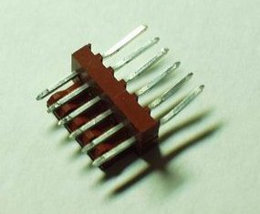
Digikey part #: WM4304-ND
Of course, we also sell them here
The polarized header is actually a right angle header. This means that the pins come bent in a right angle. Good for low profile PCB design. Also good for bending out straight and using with a breadboard!
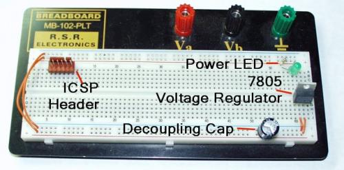
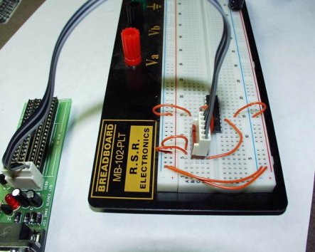
The breadboard setup
These boards can get infamously full very quickly. For that reason, this is how we like to setup our breadboards. Power on one end, micro controller stuff on the other. Jam your ICSP header in there somewhere. Get your breadboard here.
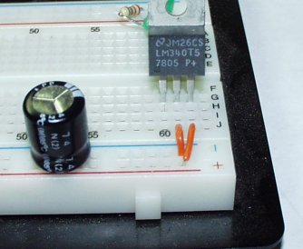
5Volt Regulator with Cap
Here is a common sight! A 7805 voltage regulator and a huge decoupling capacitor. Get them here. The 7805 has 'IGO' as it's footprint. What? IGO stands for Input, Ground, Output. You stick 9-15V on the input and you will see 5V on the output. And since the PICs like to run at 5V, this is a very good thing... And we haven't attached our wall power supply yet, so there is nothing running to the input in the picture. As for the big black electrolytic capacitor, it helps smooth out any problems with your power supply - noise, spikes, gremlins, etc. Remember, some caps are polarized, so you need to put the Pin nearest the white '-' signs in the ground row.

Leaky Caps
Just so you know, this is what happens to capacitors when you try to push too much voltage, or run them too hot for too long, or if they are reverse polarized. This is a picture of the motherboard on a Gateway computer. In the words of the Gateway phone tech - "We tried to save a few bucks on the caps, now we have to replace the mother board." In layman's terms, they used cheap capacitors to save money and the capacitors blew. Sucks to be Gateway - but they were super nice about it and shipped me a new one immediately. Oh, and don't worry about the big black cap starting to leak on our breadboard. It's rated at 50V - or 10 times higher than what we will be needing.
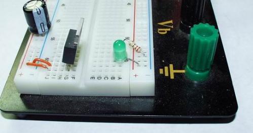
Power Indicator
It's always nice to know if the breadboard is getting power. This LED is pulled to ground through a 220Ohm resistor. Another very common setup - but super useful.
How do I connect the ICSP header?
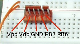
This is what needs to get connected. The last Pin on the right is not used.
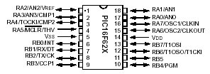
This is where the pins are located on the PIC. This information is usually within the first couple of pages of the datasheet for your specific PIC.
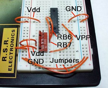
This is actually fairly clean!
Here we have the wiring required to get the ICSP header attached to a PIC. We have a 16F628 located in the breadboard. The PIC has it's power lines attached. The programmer power lines drive the power on the board. RB7 and RB6 are connected the Pins 13 and 12. Vpp of the ICSP is connected to MCLR on the 16F628. Is that enough acronyms and numbers for you? The MCLR pin must be pulled up to 12.5-13V for the PIC to go into program mode.
Once you have everything setup to your liking, get the PG2C programmer back out.
Now to program the PIC, all you have to do is plug the ICSP cable onto the polarized header. Really fast and painless.
Where others will warn you NOT to use the ICSP, we use it on a daily basis! Yes we sell programmers - and we actually use them.
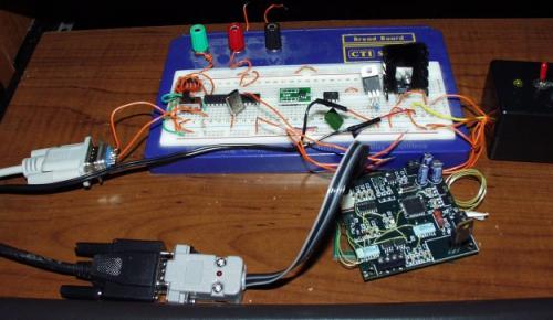
Testing the latest revision PCB.
As you can see, we favor the PG1 which has the same circuit as the PG2C, just without the socket. For this project and many of our other projects, external power is required during programming. While you should avoid using it unless you really need it, sometimes the serial port on your computer just won't cut it. External components can tax the serial port programmer enough that it cannot push the program voltage to a good 12.5V-13V level. Flash an LED and watch the programming voltage swing back and forth. Kick on external power and everything is peachy.
What NOT to do -
The only time we have experienced problems is this:
You have a serial connection as shown in the picture by the white serial cable. This cable outputs serial data from the PIC to the computer. The programmer is attached (it doesn't even have to be programming). When you turn on the power, the voltage regulator sees a ground reference provided by the white serial cable, it also sees a reference from the programmer. It tries attempts to regulate the incoming voltage based off a phantom ground which causes a large current flow. The regulator heats up and the operator quickly turns off the power, cursing at himself for being so silly. In the end, nothing is fried, harmed or otherwise smoking.
Just remember NOT to power the circuit while you've got the programmer attached and a separate ground reference coming from an external device. We've gotten around this by putting in a switch (in the picture above) near the serial cable. It's in one position for programming and the other for serial communications.
And that's about it! Have fun programming!
I'd like to see a tutorial on hooking up an MSP430 to a USB FET (such as the EZ430-F2013) via spy bi-wire. I have all these PDIP MSP430's sitting around and no idea what to do with them... since I don't have a parallel port :[
I've done it, it's fairly easy (four wires). I should write a tutorial.
Anyone else have any trouble getting ICSP working? I can program a 16f886 chip in the socket just fine but never over ICSP. I have my breadboard wired up like in this tutorial, except for the external power, and my programming program won't see it. I'm using picprog under linux for the programming. It's weird. I've verified that MCLR, VDD and GND are connected appropriately but I have no way to check ICSPDATA and ICSPCLK yet. :/
Good tutorial, except picture of header and text use RB7 and RB6 which only applies to certain PIC chips, not all of them. Pins on my PIC (12F509) are labeled ICSPDAT and ICSPCLK. So which header pin is the DATA pin and which is the CLOCK pin?
I think this is correct:
HDR1 = Vpp (MCLR)
HDR2 = Vdd (+5V)
HDR3 = GND (0v/Ground)
HDR4 = ICSPDATA/PGD/etc
HDR5 = ICSPCLK/PGC/etc
HDR6 = n/c