
Beginning Embedded Electronics - 3
Lecture 3 - What is an oscillator?
You can get all the parts for this lecture here.
Sorry for the confusion. When these tutorials were written and photographed, we used the ATmega8. We now carry the newer ATmega168. You will find all ATmega168 information in the following pages, but the pictures will show an ATmega8.
You've got the LED blinking on your ATmega168 - congrats! That's a huge step. Now it's time to make it blink faster!
You loaded code onto the chip and the ATmega168 is running that code, but how is it running? And how fast? Any micro needs a clock source. Think of it like a a type of 'musical beat' that the micro uses to to execute its code in a set manner. Without a clock, the micro doesn't know how to run the code, and with a sloppy clock (one that varies a lot) the code runs at an undetermined rate. You must have a clock of some sort and sometimes you need a very accurate clock. You ever try dancing to a CD that skips? It can be very hard!
There are many ways to generate a 'beat' for the microcontroller. The ATmega168 gives many options. Here is a quick breakdown of the different types of beat generators:
- External RC - This is generally used for *very low cost* applications. Using a resistor and a capacitor, the charge/discharge rate can be used as a clock input. I've never really used this type of clock.
- Internal RC - This is the super cool oscillator. Found on newer micros, you can just ask the ATmega168 to generate its own clock! The silicon has a built in oscillator. Unfortunately it's not very accurate.
- External Oscillator - The is the defacto standard. Attach a quartz crystal ('crystal' for short) to the two osc pins and the code executes at this given frequency.
- External Resonator - A resonator is a bit cheaper than an oscillator but has worse tolerances.
- External Clock - Instead of an oscillator, you can use a powered clock driver. Handy if you have multiple devices that need to run on the same frequency. I've never used this option.
For some great information about clock sources and their uses, checkout this app note from AVRFreaks.
I really only use 3 out of these 5 options so I'm going to delve into them more:
Internal RC -
Atmel is very smart! They ship the ATmega168 preconfigured to use the 1MHz internal oscillator. The ATmega168 (and AVRs in general) can operate at 1 instruction per clock cycle. This means that every time the oscillator goes through one cycle, one instruction is completed (this is roughly true - there are some instructions that take more than one clock cycle). Because we are using stock ATmega168s, we are running the blink code at 1MHz or 1MIPS (million instructions per second). You read that right - 1 million things a second! That's pretty impressive. What's the problem with the internal osc? It has a tolerance of +/-5% and a max speed of 8MHz. +/-5% tolerance means your ATmega168 might run at 1,000,000 * 1.05 = 1,050,000 IPS while your neighbors' ATmega168 runs at 1,000,000 * 0.95 = 950,000 IPS. This may not sound like much difference but in the digital world, this is huge! Also, the ATmega168 has a max speed of 20MHz (the internal osc runs max up to 8MHz) so if you really wanna push this IC to the max, you'll need a to use an external oscillator.
External Oscillator -
This one is most common type of clock source.
Quartz crystal oscillators come in all different flavors and frequencies. Some of the more common freq are 20MHz, 16MHz, 10MHz, 4MHz. There are also some frequencies like 14.7456MHz, 9.216MHz, and 32.768kHz that are available because these frequencies are multiples of speeds needed for serial communications and for timing. For example - if you need really accurate 9600bps serial communications, 9.216MHz divided by 960 = 9600. There is no integer that divides nicely into 16MHz to get 9600. So serial communications at 9.216MHz will be very accurate while serial at 16MHz will always have some small amount of error.
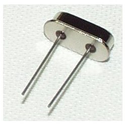
Inside the metal housing is a small piece of quartz crystal that has been precisely cut in size so that the piece of crystal vibrates at a specific frequency. The ATmega's internal osc was +/-5% tolerant. On the other hand, a crystal is normally '+/-20ppm'. This means the frequency is accurate within +/-20 parts per million! So you might have a 16,000,320MHz crystal while your neighbor has a 15,999,680MHz. This is equivalent to +/-0.00000125%. The crystal is 4 million times more accurate than the internal oscillator!
Technical note: Sorry to swamp your brain with nitty gritty details, but this is reasonably important. The silver metal device shown above is a crystal. It is not technically an oscillator. Crystals are cheap. True oscillators are expensive ($2-$4 range). What is the difference? An oscillator uses power and creates a true frequency pulse. This pulse can be used to drive all sorts of peripherals. A crystal is a purely passive device that requires some external drivers to get it to become an 'oscillator'. Luckily for us and the purposes of this tutorial, 99% of all microcontrollers have built-in circuitry so that by attaching a cheap 'crystal' to the two input pins, the internal drivers will drive the crystal, create an oscillator, and the micro will have a good clock source. Please forgive us and all the other technical documents that incorrectly use 'oscillator' and 'crystal' interchangeably.
Some negatives of crystals:
- Crystals are a bit expensive. $0.25 compared to $0.10 of a resonator.
- They cannot be made as small as a resonator (crystals take up more PCB area).
- Crystals require 'load capacitors'. Load capacitors start the crystal oscillating. Without the load caps, your crystal may function today, but someday it may not. Load caps are cheap, but they take more room on the PCB.
External Resonator -
Resonators fall in between the internal RC and a crystal.
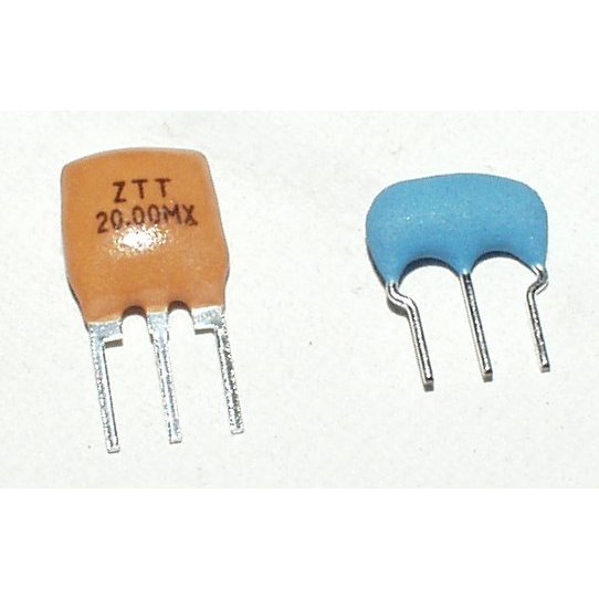
A resonator is a piece of ceramic that is manufactured in such a way to oscillate at a given frequency. Unfortunately this process is difficult to do well. Resonators have a standard tolerance of +/-0.5%. So resonators are 10 times more accurate than the internal oscillator but they are still a bit 'loose' compared to crystals.
Resonators tend to be cheaper than crystals. Resonators tend to be lower frequency than crystals. Resonators are cool because they have the 'load caps' built into the 3-pin device! Resonators can be made *very small* and can minimize your PCB area.
So pick your poison. For many applications the internal oscillator is just fine! But if you're trying to do serial communication, 5% is usually too poor (serial tolerance is 1-2%). I've used crystals for most of my projects. But for the really small devices, I've used a resonator. Anything that deals with digital RF signals requires some really tight tolerance crystals. Any oscillator will fluctuate a bit over time (this is called 'aging') and any clock will vary with temperature.
As mentioned earlier, the ATmega168 ships configured with an internal 1MHz osc. But we can push it faster - and better! Let's setup the ATmega168 to run at 16MHz with an external crystal.
What are some of the side-effects of running the ATmega168 at this higher frequency? You will not be able to run the IC at this higher freq at lower voltages (such as 3.3V or 2.8V). Since we are dealing with a 5V supply, this is not a deal breaker. At 20MHz the micro will consume more power than at 1MHz. These are all things to consider when developing your own system.
How fast can I push it?
The max speed for the ATmega168 is 20MHz or 20MIPS! That's blindingly fast!
Get your 16MHz crystal out and find pins PB6/7.
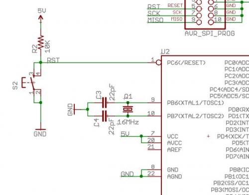
Plug the crystal legs into these two pins and connect these pins to ground through two 22pF caps.
This completes the needed hardware, now we need to tell the ATmega168 to use the external crystal.
This was one of the wildest, hardest thing to get used to with AVRs. The fuse bits are a very low-level configuration system. By setting or clearing these bits you can completely change how the AVR functions. I was a PIC guy for many years and PIC configuration bits were easy. You just clicked on a nice Windows GUI or programmed the bits directly into your C code. No fuss. AVRs are very different and you can literally break your AVR if you program the fuse bits willy-nilly.
There are two bytes on the ATmega168 that make up the 'fuse bits'. If you haven't already, download the full ATmega168 datasheet (currently it's 376 pages long!) and save it to your desktop. If you've never read a datasheet, don't worry! You don't need to know all 376 pages, you just need to know how to absorb information from it - and that's not trivial!
Let's do a search for 'fuse bits'. We get directed towards the 'Clock Sources' section. What a coincidence! (Be sure to have the book marks or section bar open so that you can see the different sections of the datasheet.) There are so many options for clock sources into the ATmega168. Let's start with tweaking the internal oscillator from 1MHz to 8MHz.
From page 34 (section 8.6): "By default, the Internal RC Oscillator provides an approximate 8.0 MHz clock. Though voltage and temperature dependent, this clock can be very accurately calibrated by the user. The device is shipped with the CKDIV8 Fuse programmed. See “System Clock Prescaler” on page 37 for more details."
So to get the internal oscillator to run faster, we need to change the CKDIV8 fuse bit.
Ahah! Here we see how the ATmega168 worked right out of the box. Atmel ships these to use the 'Calibrated Internal RC Oscillator' (8MHz) with the 'Divide clock by 8' set as well (1MHz). Very good. Now we just need to change the CKDIV8 bit.
Default Low Fuse Byte : 0b.0110.0010
New Low Fuse Byte : 0b.1110.0010
Using these new fuse bits, the ATmega168 should start running at 8MHz internal osc and we should see the LED blink 8 times as fast! There is a couple ways to do this, but the way that I've found to be most straight forward is a bit command line intense. Open up a command prompt and type 'avrdude'. You should get a mass of help text. If you're using a PG1 (serial) or PG2 (parallel) programmer, you'll need to select the right string:
To read the ATmega168 fuses:
-
PG1 (serial):
- avrdude -p m168 -P COM1 -c ponyser -U lfuse:r:-:h -U hfuse:r:-:h
-
PG2 (parallel):
- avrdude -p m168 -P lpt1 -c stk200 -U lfuse:r:-:h -U hfuse:r:-:h
Again, I am going to assume you're using the PG2, but you can modify the strings to work with a serial programmer. This basic string should cause avrdude to report back the default fuses for the ATmega168 - High fuse = 0xDF, Low fuse = 0x62
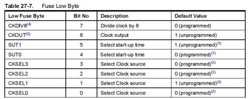
How do I form a new fuse byte? Keep searching for 'fuse bits' until you hit page 288. This shows the two fuse bytes (high and low) and their default values. All you need to do is change the lower fuse byte from 0x62 (0b.0110.0010) to 0xE2 (0b.1110.0010). Now we splice this into the previous read string and switch from read to write.
Internal 8MHz:
- avrdude -p m168 -P lpt1 -c stk200 -U lfuse:w:0xE2:m
Run this string at the command prompt and wamm-o, your AVR should be running at 8MHz. I have had a few instances where avrdude reports some errors reading the fuses and prompts if I want to 'recover' the fuse settings or some such error. I'm not sure what the error is. You can say yes/no (doesn't matter), and then send the same string. The second try should successfully set the fuses. All right, the LED should be blinking like crazy, now let's take it up one more notch to 16MHz.
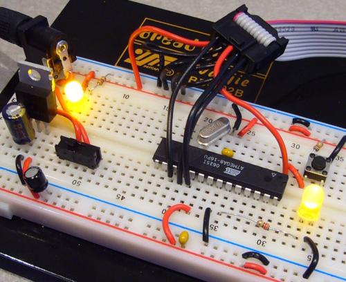
Notice how I don't have 22pF load caps on my 16MHz crystal? Bad engineer! Bad!
What are 22pF used for? These small capacitors help 'load' the crystal allowing it to oscillate. Without them, the crystal may not start oscillating - hence, your system might not run. This rarely happens, but in a full blown product, this would be disastrous! It's ok to skip them for bread boarding purposes, but good engineering practices require them.
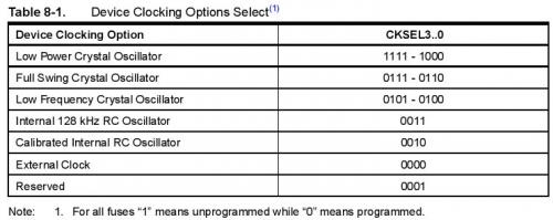
You will need to have the 16MHz crystal attached to the oscillator pins as shown in the last schematic above. Go back to the 'Clock Sources' category in the datasheet and do a bit of research for the external crystal oscillator option. I'll give you a hint, it's going to look something like this:
- CKDIV8 = 1
- CKOUT = 1
- SUT1 = 1
- SUT0 = 0
- CKSEL3 = 0
- CKSEL2 = 1
- CKSEL1 = 1
- CKSEL0 = 0
16MHz external osc:
- avrdude -p m168 -P lpt1 -c stk200 -U lfuse:w:0xE6:m
Once you get this programmed, the ATmega168 should be utilizing the external 16MHz oscillator blinking the LED super-fast. If not, check your load capacitors and the xtal connections. The ATmega168 has a maximum speed of 20MHz (20 MIPS!). Try overclocking your micro some day with a 30MHz or 40MHz crystal. More than likely it will work just fine, but you'd never want to design a real system around an out-of-spec clock speed.
Homework time. You will need to learn how to use your multimeter to measure current consumption. Because current is measured in series (voltage is measured in parallel) you will need to find a spot on your breadboard where all the current being used by your bread board can be interrupted and measured. Measure the current draw:
- When the ATmega168 is in reset = ?
- When the ATmega168 is running with 1MHz internal osc = ?
- 8MHz internal osc = ?
- 16MHz external osc = ?
A great resource that we use religiously is the AVR fuse calculator:
http://palmavr.sourceforge.net/cgi-bin/fc.cgi
Use it to double check your fuse settings and avoid permanently killing your AVR.
During each one of these experiments, do a quick temperature test of your voltage regulator. In general, the regulator should be cool enough to touch. If it's red hot (be careful!) you should turn off your breadboard and check for shorts.
Why do regulators heat up? We are using a very basic linear regulator. This type of regulator inputs a higher voltage (in my case 9V) and outputs a lower voltage (5V). The difference in voltage is expelled as heat through the metal tab. This heat is measured in wasted power or Watts. If your input is 9V, output is 5V, and your 5V system uses 50mA:
- (9 - 5) * 0.050 = 0.2W or 200mW
200mW will cause the regulator to heat up a bit. How about an amp?
- (9 - 5) * 1.000 = 4W!
That's some serious heat! The regulator will be very hot and may be permanently damaged if it's allowed to run at super-high temperatures for extended periods of time.
You may have noticed, by lowering the input voltage, we can reduce the amount of heat expelled. Why not just input 5V and call it a day? These cheap linear voltage regulators require something called 'drop-out voltage'. This is a very non-technical term for the extra voltage the regulator needs to output the required voltage. Anything below this voltage and the regulator will 'drop-out' the output voltage below the rated voltage. For LM7805 it's a good rule of thumb to have 1.5V of overhead meaning you need to input at least 6.5V to get 5V on the output. If you input less than 6.5V (4 AA batteries for instance), the 5V output is not guaranteed. Each voltage regulator is different so check the datasheet for the part in your hand! Some v-regs are specifically designed to have low drop out voltage. Some smaller v-regs have as low as 50mV! Our standard 3.3V regulator requires a minimum of 3.35V to output a solid 3.3V.
Many regulators have an internal shutdown feature that prevent the regulator from destroying itself if there is a short on the output. If you flip the power switch on your breadboard and the LED doesn't turn on, odds are your voltage regulator is trying so hard to output enough current (because you've hooked up a component backwards or worse) that the regulator shuts down and the LED has no power to illuminate. If this is the case, shut down your breadboard asap.
In general, voltage regulators will run warm. This is ok. It you ever smell something odd or you can feel a heat wave from your breadboard, just shut things down and take a second look.
You can get all the parts for this lecture here.
From now on we will run things with an external 16MHz crystal. Vary as your project needs it.
We love feedback! Please report typos, comments, or recommendations to spark@sparkfun.com.
Lecture 1 - Background and Power Supply
Lecture 2 - How to Get Code Onto a Microcontroller
Lecture 3 - What is an oscillator?
Lecture 4 - UART and Serial Communication
Lecture 5 - AVR GCC Compiling
Lecture 6 - Soldering Basics
Lecture 7 - SMD Soldering
Lecture 8 - Eagle: Schematics
Lecture 9 - Eagle: PCB Layout
Lecture 10 - Eagle: Creating a new part
Common Mistakes, Tips and Tricks
You don't need to have it plugged in to work.
Question about parallel crystals.
I have a transceiver circuit that uses a pair of crystals in parallel. Each crystal is switched in or out via a DPDT switch, thus leaving the unused crystal completely isolated from the circuit. My question is why must the unused crystal be completely isolated? Why can't one leg of each be soldered together and the other legs be switched with a SPDT switch? I see the isolation way everywhere I look but never see the common leg system anywhere.
Neat idea! I had not thought of using a mechanical switch to change crystal freqs. It will probably work... But I worry that the extra metal (capacitance) and various contact resistance will cause odd things to the frequency and may load the micro (or other device) you have the crystals and switch attached to.
Try it! And let us know how it goes.
The capacitance values shown in the schematic above imply a crystal with a load capacitance of about 16pF.
A very common misconception is that the load capacitance spec somehow comes from the processor maker. The crystal is what drives this spec. Unfortunately the processor vendors tend to get beaten up on this point, with people asking them what the cap values should be..
If the crystal specs 22pF load capacitance, then it wants to see the combination of the two caps in series, plus any parasitic capacitance, end up at 22pF. A good first shot would be ((Cload * 2) - 5) or ((22*2)-5) = 39pF. Try that value on your board, and verify oscillation frequency.
Putting 22pF caps on a 22pF crystal is not correct design, and can leave you with an oscillator circuit that won't reliably start under some conditions, and it will be slightly off frequency.
What range of load caps can be used for a 20MHz crystal? Would it be better if the capacitors would have a higher or a lower capacity? For example: 20pF vs 24pF...
The crystal data sheet tells all.
For a crystal with 22pF load capacitance spec, you will want to use roughly 39pF caps. The crystal sees these caps as in series, so you need roughly twice the spec value, and then subtract about 5pF for stray capacitance, which will depend on layout.
((22*2)-5)= 39pF.
I need help fixing my Atmega328p!
After completing the lab, I ran the command
avrdude -p m168 -P lpt1 -c stk200 -U lfuse:w:0xE1:m
and now my Atmega328p might be bricked. When I pull out and put back in the external clock, the LED goes to completely on, no blinking. When I try running ANY command, the LED goes off, and I get the following error (using -F)
avrdude: AVR device not responding
avrdude: initialization failed, rc=-1
avrdude: AVR device initialized and ready to accept instructions
avrdude: Device signature = 0x000000
avrdude: Yikes! Invalid device signature.
avrdude: Expected signature for ATMEGA328P is 1E 95 0F
avrdude: NOTE: FLASH memory has been specified, an erase cycle will be performed To disable this feature, specify the -D option.
I have searched help forums, these messages, and the only thing useful I have come up with is the following thread: http://www.avrfreaks.net/index.php?name=PNphpBB2&file=viewtopic&t=106325
which states
"A large proportion of the threads posted to this website are as a result of experiments with ISP and setting fuses that have gone wrong and left the chip in a state where it appears you can no longer do ISP any more. ... The usual "damage" is simply that you have changed the state of the CKSEL fuse bits."
Can anyone help me? I'll be sure to post the solution in our forum afterward.
Thanks!
Hi!
I need to know how to configure the fuse bits of 4Mhz and 8Mhz external crystals. I need your help!
Don't use the wrong capacitors on your oscillator!
"So you might have a 16,000,020MHz crystal while your neighbor has a 15,999,980MHz." WOW! Do you guys sell those crystals? Your AVRs must be made of liquid awesome ;)
I guess you meant Hz, and not MHz there :)
Yea I don't remember any AVR, or, any chip at all rated for 16 trillion hertz. Thats definitely a mishap/typo but common sense should catch that ;)
i have the atmega328p and am having the same problem as unebonnevie. my led is blinking with the crystal...(i had wrong caps but now have correct ones) but when trying to communicate with avr it gives me the same reply....avr device not responding.......did i fry the chip or is there a way to reset the thing????
It's always good to have all the supported oscillators in hand, when the fuse is written but the ATMega does not respond again, just try each oscillator in order, and it'll be restored, at least my ATMega48PA is restored this way.
My CPU clock can be at most set to 16MHz with 1:1 prescaler to make the avrdude still work well without any error, if I use a 20MHz crystal, avrdude will report a wrong Device signature of 0x000102 mostly, it'll still try to write flash/fuse etc, and succeed to update the flash/fuse sometimes, but always verify wrong.
I use a BSD style parallel cable of about 1.5 meter, I guess the cable is too long to have a reliable SPI signals on 20MHz clkCPU above?
hi guys. I'd appreciate any insight you can give me regarding the following inconsistency. In your guide, it's mentioned that (for the low fuse byte):
SUT1 = 1
SUT0 = 0
CKSEL0=0
But this is not match what's stated in the datasheet (page 31; Table 8-6). according to the datasheet, the configuration mentioned here is for ceramic resonators and not a crystals.
Furthermore, I tried it on the uc and it worked as expected. Please correct me if I understood wrong.
P.S.: Thank you so much for this tutorial.
I am wondering the exact same thing. Did you ever find an answer to this question?
hi,
I was wondering if you guy can help, I was able to accidently fix my problem but dont exactly understand how. I was able to hook up a avr atmega16 and create a blinking led with the internal rc clock. I follow the schematics on this article by using a Crystal 14.7456MHz external clock and connect it to the xtal2 and xtal1 which each pin of the clock are connect to a 22pf capacitor (fyi the capacitor has a print of "220" on one side and the other side has "k2j"). I connect both capicator to ground. when I change the lfuse to 0b11101111, it stop working. BUT if I disconnect the clock from ground it started WORKING!! is this the correct way to connect the clock and did I do something wrong? also I notice that the picture of the breadboard in the article connected the clock without connected it to ground as well, but I check multi sources and the schematic always connects the cystal clock to ground
thanks for the help
I also have the ATMega8 and successfully gone through the steps, everything is working great until the "avrdude -p m8 -P lpt1 -c pony-stk200 -U lfuse:w:0xE2:m" command, then suddenly, the led is full on, or maybe it is blinking too fast 16mhz, and the AVRdude is disgusted of my atmega8 and says, "Yikes! Invalid device signature.
Expected signature for ATMEGA8 is 1E 93 07", and the led goes off; power off, then back on, the led is on, and as soon as i try to reprogram, the led goes off.
to whom have fallen in the same mistake like myself, copying the commands without understanding them, i have an ATMega8, and i used the command "avrdude -p m8 -P lpt1 -c pony-stk200 -U lfuse:w:0xE2:m", as u can see, i have changed the command a bit because it didn't work with my chip and programmer, but i didn't change the value according to my chip, because the value 0xE2 does to the ATmega168, something different than what it does to the ATmega8, so what you should do before you write to your chip and render it unusable do visit the link provided "http://palmavr.sourceforge.net/cgi-bin/fc.cgi" and choose your chip, and the value you will be setting it to, and the avdude command will appear at the bottom of the page, to solve this problem, is to try to know what the command did to your chip, and in this case it has changed it to use external crystal,so u must provide it with the appropriate crystal to work
You have the fuse bits set for a low power crystal oscillator. Set lfuse to 0b11100110, so you are using a full swing crystal oscillator instead.
I'm sorry but that fuse calculator you link to is extremely confusing.
http://palmavr.sourceforge.net/cgi-bin/fc.cgi
I don't see Ext Osc 16Mhz listed.
Iv'e tried setting manually but I get completely different hex values than the tutorial gives.
The low fuse should be 11100110, correct?
But that gives a low fuse hex of 0x19.
Could some one link a resource or something on how to use that calculator.
I'm sooo lost.
I'm having the same problem as other people, but unfortunately after verifying my caps are correct I still have the problem. It was working until I ran the command 'avrdude -p m168 -P /dev/ttyS0 -c ponyser -U lfuse:w:0xe6:m' and the LED stopped blinking. My Atmega168 is now "not responding". I'm certain I have 22pF caps before my crystal, and there is ground going through the crystal (hooking up one lead to VCC and one to a leg of the crystal gives me ~5V). Does anyone know how I could save my Atmega?
Well, after reading several comments and saying to myself "I'M NOT GOING TO PUT THE WRONG CAPS IN!"...I put the wrong caps in...works better now...
Is there some standard way of reading the codes on these things? Do these teeny tiny letters actual mean anything? Anyway to check what the actual value is?
stupid caps...
The capacitors are coded in pF, with the last number being the amount of zeros that follow first two numbers, make sense?
Example:the 220 on the one side means 22 with 0 0's or 22pF.
Your .1uF caps should have 104 on one side.
104 = 10 0000 = 100,000pF = 0.1uF.
Is the ATmega168 and ATmega8 identical besides the more memory? If I were to follow the tutorial with an ATmega8 would I get the same results?
I had the same problem as unebonnevie. Everything worked beauitfully until I sent the "avrdude -p m168 -P COM1 -c ponyser -U lfuse:w:0xe6:m" command. The LED shut off and now any attmept to read or write to the atmega168 with avrdude produces a "AVR device not responding" message. Similar to unebonnevie, it no longer has a valid device signature. It is now 0x000000 and used to be 0x1e9406.
Ignore my previous post. Similar to Malweth, I put in the wrong cap but unlike Malweth's situation my crystal did not oscillate with out the caps.
Hi,
Have successfully completed lectures 1,2,3. However, tried to run my app. with the parallel cable disconnected from computer and it wouldn't run. Why not? Which leads to the question - if you develop a device that actually accomplishes something useful, how does the atmega168 need to be wired once the parallel cable connectors are removed? I tried the datasheet to see if I could figure this out, but not a hope.
Think I hit the willy-nilly problem. "AVRs are very different and you can literally break your AVR if you program the fuse bits willy-nilly."
Going along fine until I tried to program the fuse bits for the external clock mode and then wham-o, The light turned off and I can't even read a valid chip id anymore
Think my AVR is hosed?
Have a new AVR and up and running. Lets not be willy nilly anymore.
Everything has worked well up until trying to use avrdude to set the low fuse value to hex E6. avrdude reports that E6 is an invalid byte value for use in immediate mode. Any ideas anyone?
OK, my bad, I typed O instead of 0 into the command line. However, based on the data sheet for the atmega168, I used 0xEF for the low fuse byte, rather than the 0xE6 as stated in the tutorial. They both work, but the data sheet indicates that CKSEL3 needs to be 1. Any comments?
How would I know that 4W is too much for the regulator besides trying it out and finding out it gets hot?
Can someone give a hand here.I am new to this.Where do i go on the AVR's Programmer Notepad to change it to a CLI.Or is it possible to use the inhouse CLI from DOS
Once the crystal is connected to PB6 and PB7 and the fuse bits are set to use it, can you use these ports as I/O again (assuming you reset the fuse bits to their original values)....
Well, I've been struggling with tutorial as others have for the last few days, and someone should check behind me but I think i've got something going here for the atmega8 people on a few problems
avrdude -p m8 -P COM1 -c ponyser -U lfuse:w:0xE4:m
did the trick for the Device not found stuff
and 0xE4 works (i believe) to set to 8mhz Internal RC osc and disable the chkdiv8 bit.. referring to table 9 under clock sources that is in atmega8 datasheet, E6 which is 0110 isnt assigned to any clock speed and so im guessing defaults to the 1mhz?
I'm wrapping my head around your exact question: You are correct - the ATmega's ship with the default 1MHz internal osc set. Sounds like you successfully removed the clock/8 setting, allowing the chip to run at 8MHz with the internal oscillator. Good!
Oh, man...
Before wiring up the crystal and the caps in, avrdude read the fuse bits correctly on my ATMEGA8-16PU (16Mhz max.) and output two bytes, 0xe1 and 0xd9 in that order. Then I turned off the power and wired the crystal in and avrdude wrote 1 byte of lfuse, byte 0xE6, as well as verified it. Now the LED does not blink at all!
I attempted to do a read again and get the below.
avrdude: AVR device not responding
avrdude: initialization failed, rc=-1
Double check connections and try again, or use -F to override this check.
Tips? Thx
AVRDude now says my ATMEGA8 device signature is 0xffffff. The correct device id is 0x1E9307.
avrdude: Device signature = 0xffffff
I had the same problem. I was using the ATMega168, but my situation was otherwise identical. I turned off the power, removed the 22pF caps and it is blinking like a champ!
I don't have an O-scope to figure out what was going on, but I verified this by setting the low fuse bit back to 62, replacing the caps, and setting it back again to E6.
Sure was to find out I hadn't bricked my first AVR.
Such an obvious mistake I made.
The reason why my Crystal wasn't driven using the capacitors... I put the wrong caps in! I used the .1 uF instead of the 22 pF caps.
About four times the capacitance surely helped stop any oscillation.