Engineering Essentials
Electrical engineering is a technical discipline concerned with the study, design, and application of electricity! Through electrical engineering, we can design devices and systems using electrical components such as resistors, capacitors, transistors, etc. Electrical Engineers can design and work on items such as super low power microcontrollers, PCB Design, high power turbines, navigation systems, etc.
Get a brief overview and dive deeper into all our electrical engineering essentials below.
Metric Prefixes & International System of Units (SI Units):
When you're getting into electrical engineering, it's important to know common electronic units and prefixes.
| Quantity | SI Unit | Abbreviation |
|---|---|---|
| Voltage | volts | V |
| Current | ampere | A |
| Power | watt | W |
| Energy | joule | J |
| Electric charge | coulomb | C |
| Resistance | ohm | Ω |
| Capacitance | farad | F |
| Inductance | henry | H |
| Frequency | hertz | Hz |
| Prefix | Power | Numeric Representation |
|---|---|---|
| tera (T) | 1012 | 1 trillion |
| giga (G) | 109 | 1 billion |
| mega (M) | 106 | 1 million |
| kilo (k) | 103 | 1 thousand |
| no prefix | 100 | 1 unit |
| milli (m) | 10-3 | 1 thousandth |
| micro (μ) | 10-6 | 1 millionth |
| nano (n) | 10-9 | 1 billionth |
| pico (p) | 10-12 | 1 trillionth |
Full list of Prefixes and SI Units
What is Electricity?

Electricity is all around us in our everyday lives. Even when you're not using any electronic equipment, electrical signals course through your nervous system to instruct your body on what to do.
Electricity is briefly defined as the flow of electric charge, but there's much more to it. When dealing with electronics, you will be dealing mainly with current electricity. However, you may find yourself asking, "Where do the charges come from? How do we move them? Where do they move to? How does an electric charge cause mechanical motion or make things light up?" To begin to explain electricity, we need to zoom way in, beyond the matter and molecules, to the atoms that make up everything we interact with in life. Dive in or get a quick refresher with our tutorial on the natural phenomenon we call electricity.
Electric Power
For electronics to function they require power. Our phones are receiving power from their rechargeable batteries, and our computers receive power from a 120 (or 220) Volt AC outlet that gets converted to 12 or 18 Volts DC. Power is one of the most fundamental concepts when it comes to electronics.
In general, more power means more energy. We can calculate power using the various SI units from above. Energy is measured in terms of joules, and power is a measure of energy over a set amount of time; therefore, we can measure energy as joules per second, which is also known as the "watt."
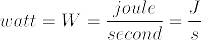
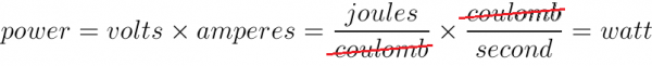
Once you can calculate a watt, you can use a more common equation for calculating power.

Working with Wire
Electrical wire comes in two different forms: either solid core or stranded core. Solid core is a solid wire, and stranded core is many solid wires all bundled into a group. Stranded wire is a lot more flexible to work with than solid core, however it's more difficult to use in a breadboard or when PTH soldering.
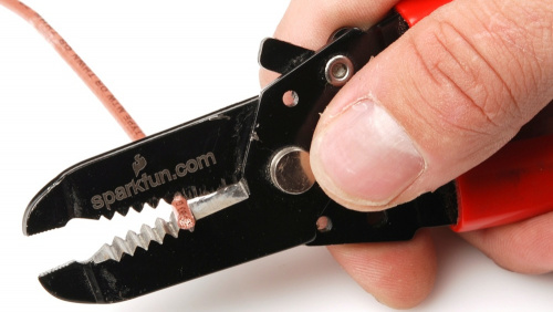
Wires also come in different gauges. The gauge or thickness of a wire is used to determine the amount of current a wire can safely handle – in general, the thicker the wire the more current it can carry. Most wire strippers will have corresponding gauge slots for easy and accurate wire-stripping, and we can splice wires together by stripping their ends, soldering them together and then re-sheathing the exposed wire with heat shrink electrical tape, or some other sheathing material to the solder joint to cover the exposed connection. For a more in-depth look on stripping wires, splicing them and various types of crimps (connectors), check out our Working with Wire tutorial.
Connector Basics
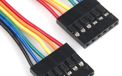
Connectors are used to join different sections of circuits together. There are many types of connectors, and all are gendered.
For example, the power adapter from the wall outlet that charges your phone is a common type of connector. If it plugs into another connector, then it is said to be a male connector, if it gets plugged into by another connector then it is a female connector. Most connectors have a polarity; for example, modern wall plugs have two different widths for the plug blades. This connector is polarized because it will only plug into the wall one way. If you want to learn more basic connector terminology, identify polarized connectors and learn which connectors are best suited for certain applications, you can follow along with our tutorial.
Intro to Circuits
Every electronics project begins with a circuit. Here we will talk about the basics of a circuit, go over Ohm’s Law, discuss how to tell whether a circuit is in series or parallel, and talk about opamps.
What is a Circuit?
You can think of a circuit as the flow of electric current in a circular path that starts and stops in the same place.
Figure 1: Basic Circuit
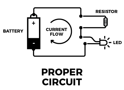
When using a voltage source we add what is known as a ”load” to the circuit. This can be LED’s, resistors, etc. Basically anything that will cause a voltage drop because the electrical current wants to flow from a higher voltage to a lower voltage.
Figure 2: Short Circuit
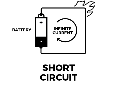
If no load is present in the circuit, it's a short circuit. This is dangerous, because there is nothing to restrict the current flow, and you can end up with burned wires, damage to the voltage source or a quickly-drained (or exploded!) battery.
Figure 3: Open Circuit
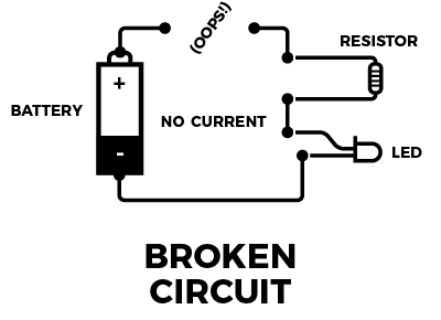
This is an open or broken circuit, which is a circuit that is incomplete. Although not dangerous like the short circuit, it will ultimately fail to work because voltage can’t reach the components.
Voltage, Current, Resistance and Ohm's Law
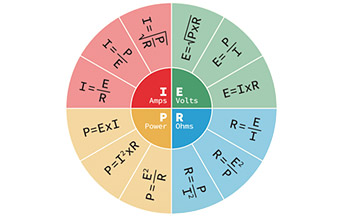
When exploring the world of electronics, it is vital to start by understanding the basics of voltage, current and resistance. These are the three basic building blocks required to manipulate and utilize electricity.

With a constant voltage source, we can see how current and resistance change. With a high resistance, there will be very low current flowing through the load. With a low resistance, we will see the opposite. We can use Ohm's law in conjunction with the power equation to determine any electrical characteristic (power, voltage, current, or resistance) as long as we know 2 of the other quantities. To get a full understanding of the relationship between voltage, current and resistance, view our tutorial on Ohm's Law.
Series and Parallel Circuits
Simple circuits (ones with only a few components) are usually fairly straightforward, but things can get sticky when other, more complicated components are involved. This is where series and parallel circuits come into play.
When looking at the difference between circuits in series and circuits in parallel. First we need to know what a node is that way we can determine whether or not a circuit is in series or parallel. Referring to figure below we can see that R2, R3, and R4 are all connected to the same node (The teal-blue wire). This is where the current would split representing a parallel circuit. Between R1 and R2 there is a node but the current does not split, so this is an example of a series circuit.
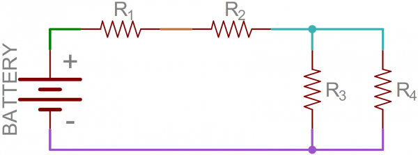
Example schematic with four uniquely colored nodes.
Remember: two components are in series if they share a common node and if the same amount of current flows through them. If two components share two common nodes then they are in parallel.
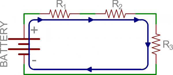
Series circuit
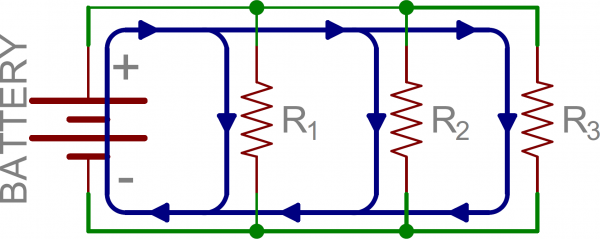
Parallel circuit
Reading Schematics
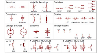
Schematics are the maps for designing, building and troubleshooting circuits. Understanding how to read and follow schematics is an important skill for any electrical engineer.
Each part of a circuit, from transistors to switches, has its own schematic symbol.
Tools We Use
In addition to proficiency in all the electronics topics listed above, electrical engineers are also required to have the knowledge and skills to use a multitude of different tools. Let's go over some of the essentials.
Multimeter
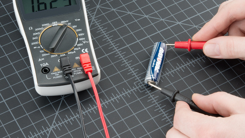
Arguably the most indispensable tool in an electrical engineer's arsenal is a multimeter. Besides measuring voltage and current, a multimeter can also help you diagnose circuits, learn about existing electronic designs and even test a battery. They can also do a continuity test to make sure traces and components are connected properly. Take a look at our full guide and video to get started and see the different multimeters we carry.
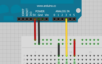
Breadboard
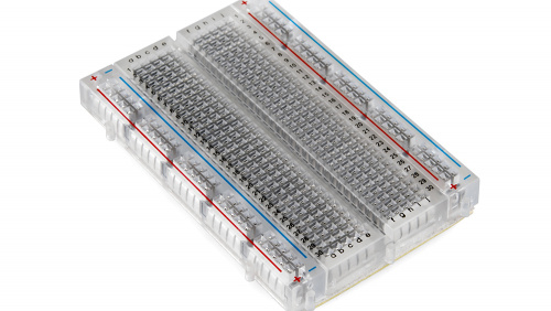
Breadboards are one of the most fundamental pieces of learning how to build circuits. A breadboard is generally used for prototyping as it is easy to replace components, diagnose issues and test without needing to solder.
Oscilloscope
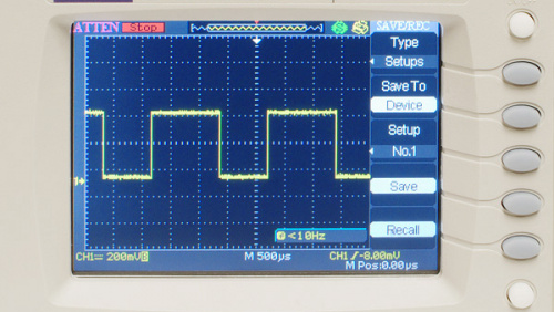
An oscilloscope is used when a signal needs to be analyzed (amplitude, period, clock cycle, etc.). An oscilloscope's probe reads various types of signals, such as continuous and discrete, so both analog and digital signals can be displayed to the user.
The trusty o-scope is very versatile, and is useful in a variety of troubleshooting and research situations, including:
- Determining the frequency and amplitude of a signal, which can be critical in debugging a circuit's input, output, or internal systems. From this, you can tell if a component in your circuit has malfunctioned.
- Identifying how much noise is in your circuit.
- Identifying the shape of a wave -- sine, square, triangle, sawtooth, complex, etc.
- Quantifying phase differences between two different signals.
Soldering Iron
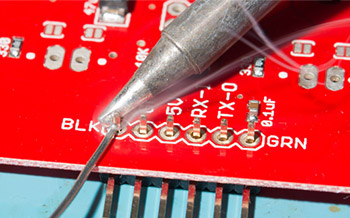
Soldering is one of the most fundamental skills needed when working with electronics. You only need an iron, solder and soldering tips in order to begin.
There are other helpful terms and tools to know if you want to learn to solder. The tip is the part of the iron that heats up and allows the solder to flow around the two components being joined. Most soldering irons have the option to change the tip if one is damaged or you need a different tip for the task at hand. Soldering wick allows you to remove solder so it is easier to move a component. Tip tinner removes the oxidation that builds up at the soldering tip so you can get the most heat transfer from your tip. Flux is extremely useful – it's a chemical agent that healps lead-free solder flow smoothly. A tutorial on soldering irons and various tools can be found below.
Analog vs. Digital Signals
A signal consists of a time-varying quantity that allows us to visually see how the circuit is interacting with the various components. For us, this time-varying quantity is most likely voltage or current. When it comes to working with electronics we deal with both analog and digital signals, which can occur as both an input and an output. Projects we create have to interact with the real, analog world in some way, but most microprocessors, computers and logic circuits are built using purely digital components.
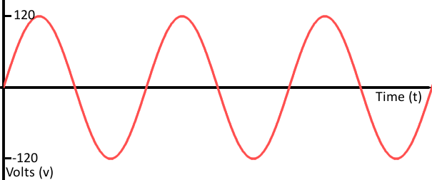
Analog:
Analog signals are a smooth continuous plot, with voltage on the y-axis and time (usually in seconds) on the x-axis. An example of an analog signal can be seen in figure 6. Some of the most common analog components are resistors, capacitors, inductors, diodes and transistors.
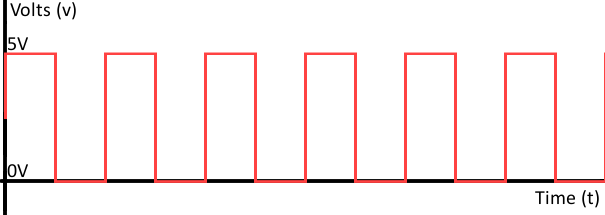
Digital:
Digital signals must have a finite set of possible values. Most digital signals oscillate between two fixed values. An example of an analog signal can be seen in figure 7. Most communication between integrated circuits is digital, such as serial communication, I2C, and SPI, which we will go over in more detail later.
Analog-to-Digital Conversion (ADC):
Most microcontrollers have an ADC built in, which allows us to read an analog signal from the outside world and convert it to a digital signal. You will know if the board you are working with has ADC pins, because most board manufacturers will have an ”A” in front of their label (A0- A7 for example).
Digital signals are easier to work with because they consist of only two fixed values. For example, if the digital signal outputs 5V, we can convert that into a 1 in binary, which would portray an active pin (high pin). If 0V is the output, we can convert that into a 0 in binary, which would show the pin is off.
Diving into Analog
Here we will discuss the most common analog components: capacitors, diodes, voltage dividers and transistors.
Capacitors
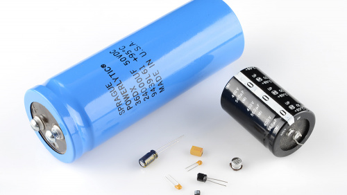
A capacitor is a two-terminal electrical component. Along with resistors and inductors, they are one of the most fundamental passive components we use.
When current flows into a capacitor, the charge gets stuck on the plates when it can't get past the insulating dielectric. Because the electrons are stuck to one of the plates, the capacitor becomes negatively charged. The negative charge on one plate pushes away similar charges on the opposite plate, making it positively charged. The stationary charges on these plates create an electric field that influences voltage, resulting in the capacitor becoming charged. You can calculate the charge in a capacitor with the following equation.

In order to calculate the current through a capacitor we use the following equation:
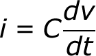
Here, dv/dt is the derivative of voltage. If the voltage is constant, then the current going through the capacitor is 0 because the derivative of a constant number is 0. This is why current cannot flow through a capacitor holding a steady voltage.
Diodes
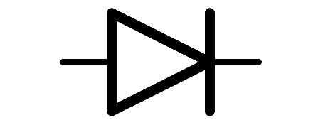
The function of a diode is to control the direction of current flow. Current passing through a diode can only go in one direction - forward.
Current trying to flow the reverse direction is blocked. If the voltage across a diode is negative, no current can flow and the resulting circuit acts as an open circuit; in this situation the diode is said to be reverse-biased. A diode has two terminals: the anode (positive terminal) and the cathode (negative terminal). Below is a chart regarding diode characteristics.
| Operation Mode | On (Forward-Biased) | Off (Reverse-Biased) |
|---|---|---|
| Current Through | I > 0 | I = 0 |
| Voltage Across | V = 0 | V < 0 |
| Diode Acts Like | Short Circuit | Open Circuit |
There is a third characteristic of a diode called breakdown. When the voltage applied across the diode is very large and negative, a lot of current will be able to flow in the reverse direction, from cathode to anode.
LEDs act as normal diodes and only allow current to flow in one direction. They also have a forward voltage rating, which is the voltage required for them to light up.
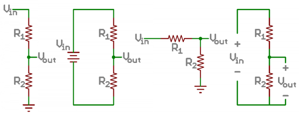
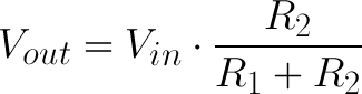
Voltage Dividers
A voltage divider is a circuit that turns a large voltage into a smaller one.
Using just two series resistors and an input voltage, we can create an output voltage that is a fraction of the input. Voltage dividers are one of the most fundamental circuits in electronics. You may see them drawn a few different ways, but they should always essentially be the same circuit. And remember, any part of your system that pulls current is kind of like adding another resistor to the network, so don't forget to include all potential loads on any nodes!
The equation used to calculate the output voltage (or one of the other values) is as follows.
Diving into Digital
Here we will discuss binary, which is how a computer reads data (1s and 0s), as well as how logic levers work.
Binary
Most people are used to thinking about numbers as the decimal values, or base-10 numeral system. Electronics, however, think about numbers in binary, or base-2 numeral system. Binary also has bitwise operators: the complement, and, or, & xor.
| String 1 | String 2 | |
|---|---|---|
| Operator | 11110000 | 10101010 |
| Compliment | 00001111 | 01010101 |
| or | 10100000 |
|---|---|
| or | 11111010 |
| xor | 01011010 |
Here we use the same two strings defined above when computing the compliment.
Logic Levels
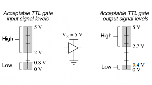
A logic level is a state in which a signal can exist. Often in digital circuits this state is either on or off, a 1 or a 0 in binary respectively. Many microcontrollers today also have active-low and active-high pins.
Active-low pins must be pulled by connecting it to ground and active-high pins are connected to the input voltage which is usually either 3.3V or 5V depending on the microcontrollers datasheet.
Communication protocols
Many communication protocols can be separated into two categories: parallel or serial communication. Parallel interfaces transfer several bits at the same time and require a bus to transfer data, whereas serial interfaces transfer data one bit at a time. Serial communication has several rules to follow:
- Data bits: The data you want to send (such as an ASCII character) converted into an 8-bit number.
- Synchronization bits: Start bits and stop bits start the beginning and end to a packet. There is always only one start bit, but there can be up to two stop bits.
- Parity bits: Low-level error checking, which is optional and rarely used due to it slowing down the data transfer.
- Baud rate: How fast data is sent over a serial line - expressed in units of bits/second (bps).
Universal Asynchronous Receiver/Transmitter (UART)
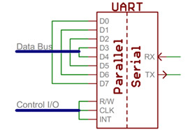
A universal asynchronous receiver/transmitter (UART) is a block that implements serial communication by having both parallel and serial interfaces.
One side (parallel) consists of data lines, and the other side (serial) has the transmit (TX) and receive (RX) lines. Never connect TX to TX and RX to RX! The wires should cross, TX should be connected to RX, and RX should be connected to TX between the separate serial communication devices. UARTs do exist as stand-alone ICs, but they're more commonly found inside microcontrollers.
Serial Peripheral Interface (SPI):
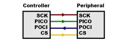
SPI is an interface bus used to send data between microcontrollers and small components, like sensors and SD cards.
SPI works in a slightly different manner than serial communication - it uses a synchronous data bus rather than an asynchronous data bus. With this in mind, it uses separate lines for data and a clock that keeps both the receiving and transmitting side in perfect sync with one another. The clock is an oscillating signal that tells the receiver exactly when to sample the bits on the data line. This is either the rising or falling edge of the clock signal. When the receiver detects that edge, it will immediately look at the data line to read the next bit. One reason SPI is popular is that the receiving hardware can be a simple shift register - simpler and cheaper than the UART, which is required by asynchronous serial communication.
Inter-Integrated Circuit (I2C)
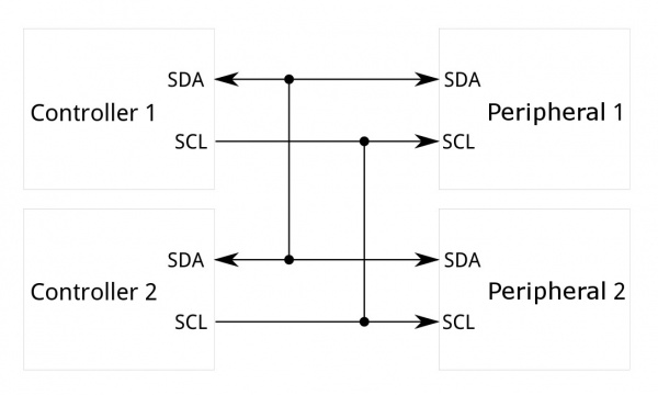
The Inter-Integrated Circuit (I2C) Protocol is intended to allow multiple "peripheral" digital integrated circuits ("chips") to communicate with one or more "controller" chips.
Like SPI, it is only intended for short distance communications within a single device. Like ASIs (such as RS-232 or UART), it only requires two signal wires to exchange information. SparkFun's Qwiic Connect System takes advantage of the benefits of I2C to allow different sensors, actuators, displays and more to be daisy-chained together with a polarized cable.