Go Speed Racer...Arduino Speed Test
We often teach beginning learners that the standard 16 MHz Arduino Uno is fast... really fast. 16 MHz means 16 Million cycles per second -- or that translates to 1/16 millionths of a second per cycle. That's a mere 62.5 ns. That's fast. So, is the Arduino _really_ that fast? Let's see...

How fast is an Arduino?
We spend a lot of our time teaching educators and teachers the ins and outs of Arduino and basic microcontrollers.
When we introduce the standard Arduino Uno, we often point out that there's a crystal oscillator running at 16 MHz. Depending on the audience, we often generalize that the microcontroller runs at 16 MHz, or to put this into perspective, this means 16 Million operations (instructions) per second. Put another way, it takes 1 / 16 millionths of a second to perform a single operation -- or just 62.5 nanoseconds!
Is that really true?
So, I wanted to figure out how far off am I really? I know that the Arduino environment has quite a bit of overhead, and also every instruction actually requires multiple commands and memory reads and writes, but what is the 'maximum' running speed of the loop() in Arduino?
So, I devised a couple tests. The first was a simple sketch that looked like this:
void setup()
{
    pinMode(13, OUTPUT);
}
void loop()
{
    digitalWrite(13, HIGH);
    digitalWrite(13, LOW);
}
This is about as simple as it gets. Anyone who's ever tried running this code knows that the LED will blink ON and then OFF faster than we can see. I was curious as to how fast this really ran. Well let's take a look:
Here is a quick trace of the pin:

It looks like the digitalWrite(13, HIGH) takes roughly 3.95 uS and the digitalWrite(13, LOW) takes about 4.55 uS. The total time being 8.5 uS. This is much longer than 62.5 ns. In fact, it's 136 times longer.
It appears that the LOW was longer than the HIGH. I wanted to see
void setup()
{
    pinMode(13, OUTPUT);
}
void loop()
{
    digitalWrite(13, HIGH);
    digitalWrite(13, HIGH);
    digitalWrite(13, LOW);
}
Now, with two HIGHs and one LOW, I'd expect the HIGH to be around 7.9 uS (2 x 3.95 uS) and the LOW to still be 4.55 uS. Here's the trace from my oscilloscope:
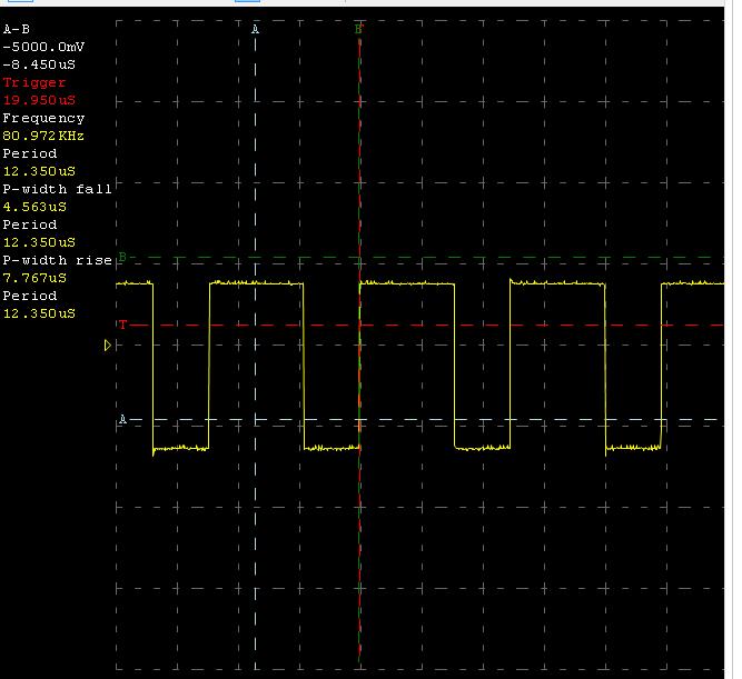
The results? Well, the two 'HIGH' instructions looked like they took a total of 7.767 uS --> about 3.884 uS per instruction. That's pretty close. And the 'LOW' instruction stayed right at 4.563 uS.
Okay -- so, if about sending a sequence of HIGH-LOW-LOW?
void setup()
{
    pinMode(13, OUTPUT);
}
void loop()
{
    digitalWrite(13, HIGH);
    digitalWrite(13, LOW);
    digitalWrite(13, LOW);
}
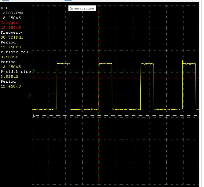
The singular 'HIGH' instruction is right at 3.925 uS -- as expected. The two sequential 'LOW' instructions take up 8.5 uS in time -- a bit smaller than the expected 9.1 uS (2 x 4.55 uS).
All in all, I found this to be both intersting and insightful. What does this mean? Well - at maximum speed, it looks like within the main loop() of Arduino we can toggle a pin at a rate of about 117 kHz.
Ok - so, this is quite a bit slower than the 16 MHz clock, but -- I'm sure if we integrated into the timer interrupts directly or stripped things down a little more, we might be able to manipulate bits / pins at a faster speed. For me, for blinking LEDs, driving motors, and reading sensors -- 117 kHz is plenty fast!


You're right that you can't toggle an LED at 16 MHz using the Arduino libraries, but that's not the hardware's fault. It's the result of using the Arduino libraries, which as jweather says, are not exactly optimized for speed. digitalWrite() is not a single instruction, but a call to a C function that does lots of checking and setup stuff before it actually sets the pin output. This makes it quite slow. In your example, there are no interrupts and no serial checking, so everything can be blamed squarely on digitalWrite(). :-)
You overlooked one thing in your analysis, which is that when the program reaches the end of loop(), it must jump back to the beginning of loop(). This involves additional function calls in the Arduino library, and takes a small amount of time, and explains why your LED was in the low state longer than it was high. If you switched the low and high lines of your loop, you'd see that the LED was high longer than it was low. There's nothing inherently slower about setting a pin low than high.
I would encourage anyone who needs faster Arduino performance, or is just curious, to look at the source code for the Arduino libraries. Look at what digitalWrite() actually does. Read the Atmel datasheet for the ATMEGA328 chip. Read about direct I/O port manipulation here: http://playground.arduino.cc/Learning/PortManipulation . You don't necessarily need to write code in assembly language to get fast performance. With a program like:
you should be able to get LED blinking performance much closer to 16 MHz.
Even with this code the loop has 3 instructions and 4 clock ticks. I'd expect a rectangular wave with a frequency closer to 4MHz. 1 clock tick low, 3 clock ticks high.
Good point. If you unroll the loop a little, you can get intervals of full-speed LED blinking: 62.5ns off, 62.5ns on, blink frequency of 8 MHz. So if there was any doubt, yes the Arduino really can perform a single operation in 1 / 16 millionth of a second!
Here's my test program, no assembly language required:
And logic analyzer output to show that it really does toggle the LED every 62.5 ns:
Saleae logic analyzer screenshot
Wow -- Thank you, Steve and everyone else! This is great community grassroots work. Arduino hides / masks a lot of subtle details that teachers and beginners often never see.
One example is what is inside the main.cpp. In the current version of Arduino it looks like this -- it's not a
while(1){}-- well, it is -- but it's written as an empty for() loop.Then, if we dig into the digitalWrite() -- it looks ugly -- kind of like this:
I agree that a straight PORTB memory write is probably the most efficient -- but, who's going to remember how which bit to shift? And moreover -- how often do our student need this speed? For me, it's
digitalWrite(13, HIGH)-- I suppose this really just shows how much overhread Arduino is adding on!This is why one of the things that I have in FastLED is fast pin access. If you know the pins at compile time, it lets you toggle them on or off in as little as 2 clock cycles.
The one problem with the direct port access mentioned above is that it will turn the other 7 pins on PORTB off. There are games you can play to work around that, and in some places, FastLED does do its pin toggles in a single clock cycle (and on many arm platforms, you have separate i/o registers for setting pins hi and lo, which allows you to just write the 1<<X bit to a hi/lo register to toggle a pin high/low without worrying about preserving the existing register values).
digitalWrite() is not particularly fast -- it has several unnecessary lookups, including checking each time to see if it needs to turn off the PWM timer for that pin after a previous analogWrite(). The fastest, but least convenient method, is direct assembly commands. A compromise that worked well with my project (playing music on stepper motors) was a more efficient I/O library: http://www.codeproject.com/Articles/732646/Fast-digital-I-O-for-Arduino
I think one reason you aren't seeing anything close to 16 MHz, is that each call to digitalWrite() is not one instruction, but rather one call to a function. digitalWrite() would make another series of function calls and so forth until eventually (after compilation) we get a list of assembler instructions to actually toggle a hardware pin. That list could be tens of instructions long (or more). Any other thoughts?
Compiler inserting ASM commands that are unnecessary.
If you REALLY want to try this, write the program in ASM and then run it on the Arduino. You'll have something slower, but not in uS. This is a use case that they teach in college on MCUs and compilers.
If you want to push it 'all the way', check out this project: http://blog.blinkenlight.net/experiments/counting/faster-counter/ This blogger got a gray code counter to toggle his LEDs at 99.9% of his Arduino's clock speed. Not useful for much, but interesting.
The other thing that is important to note (and the tests dis not yet demonstrate) was not that the low was taking longer, but that the internal loop command is also taking time in the Arduino (which is why the other people here are adding a seemingly redundant while(1)). the time taken by the digitalWrite is probably the same for both.
That's exactly right. As for how many instructions are being called, I haven't dug in that far. I also suspect that the interrupt handlers, the Serial checking, and the multiple "assembly level" instructions are all adding overhead as well.