3D Printed Illuminated Wand Prop
 bboyho
Understanding Your Circuit
The circuit is simple and consists of an LED, 10Ω resistor, LilyPad switch, and a battery holder. I chose to add a current limiting resistor between the anode (longer leg) of the LED and "+" terminal of the battery holder. The resistor was probably not necessary since a coin cell is not able to source enough current to damage the LED. Nonetheless, a resistor was still added as good practice. The LilyPad switch was added between the cathode (shorter leg) of the LED and the "--" terminal of the battery holder.
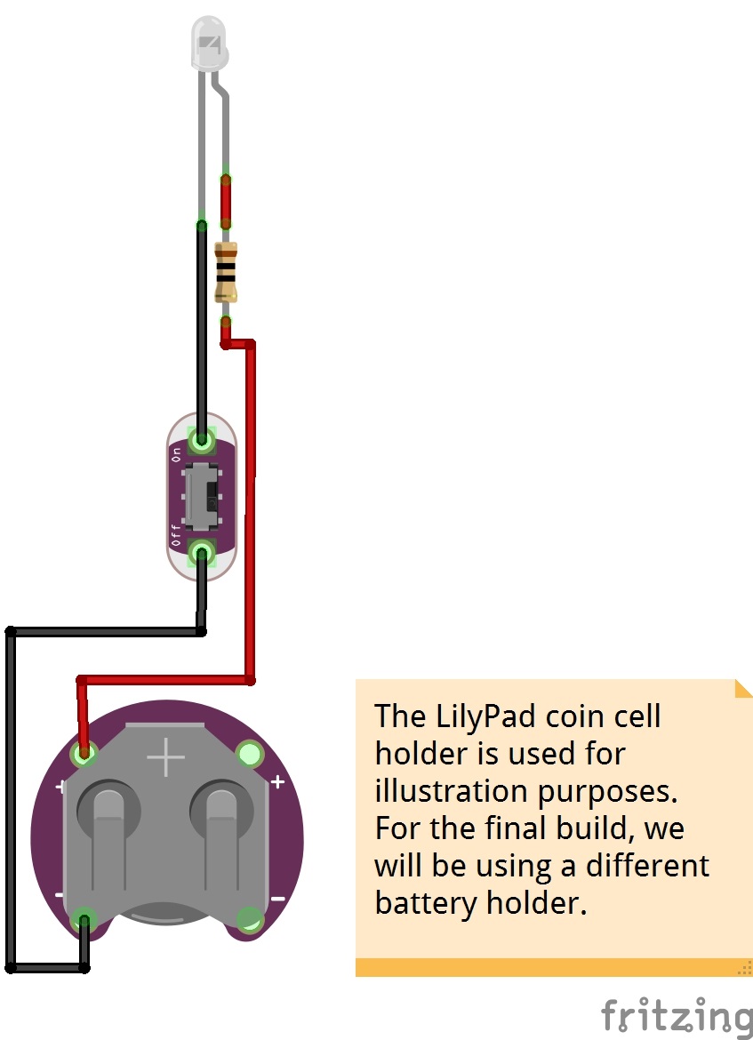
While the orientation of the switch did not affect the overall functionality of the circuit, I did decided to have the ON side of the LilyPad switch facing toward the LED for the user. Also, the LilyPad coin cell holder was a bit big compared to the size of the wand so a smaller holder was chosen for the project. There will be markings on the holder to indicate the "+" and "--" terminals with the alternative holder.
 |
 |
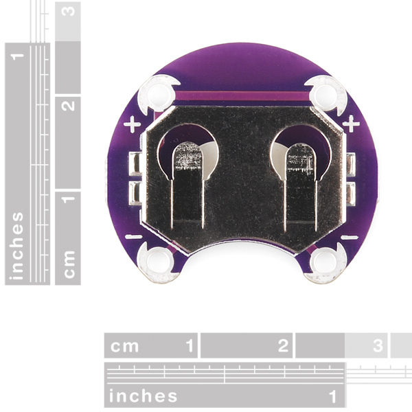
| Dimension of LilyPad Coin Cell Holder [PRT-10730] |
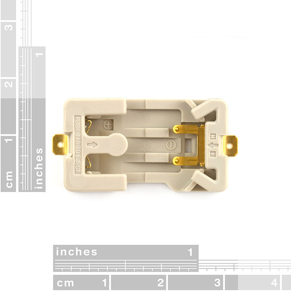
Dimension of Coin Cell Holder [DEV-08822] |