Activity Guide for SparkFun Tinker Kit
This Tutorial is Retired!
This tutorial covers concepts or technologies that are no longer current. It's still here for you to read and enjoy, but may not be as useful as our newest tutorials.
View the updated tutorial: Tinker Kit Circuit Guide
 Joel_E_B,
  bboyho
 Circuit 1: Blink an LED
Light-Emitting Diodes, or LEDs (pronounced el-ee-dees), are small, powerful lights that are used in many different applications. You can find LEDs in just about any source of light nowadays, from the bulbs lighting your home to the tiny status lights flashing on your home electronics. Blinking an LED is the classic starting point for learning how to program embedded electronics. It's the "Hello, World!" of microcontrollers.
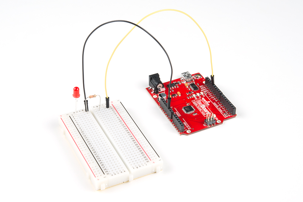
In this circuit, you’ll write code that makes an LED flash on and off. This will teach you how to build a circuit, write a short program and upload that program to your RedBoard.
Parts Needed
You will need the following parts:
- 1x Breadboard
- 1x SparkFun RedBoard
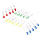
- 1x Red LED
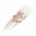
- 1x 330Ω Resistor
- 2x Jumper Wires
Didn't Get the Tinker Kit?
If you are conducting this experiment and didn't get the Tinker Kit, we suggest using these parts:


New Components
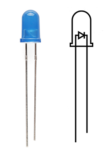
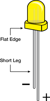
LED (Light Emitting Diode)
Light-Emitting Diodes (LEDs) are small lights made from a silicon diode. They come in different colors, brightnesses and sizes. LEDs have a positive (+) leg and a negative (-) leg, and they will only let electricity flow through them in one direction. LEDs can also burn out if too much electricity flows through them, so you should always use a resistor to limit the current when you wire an LED into a circuit.
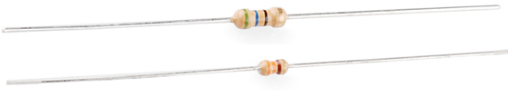
Resistors
Resistors resist the flow of electricity. You can use them to protect sensitive components like LEDs. The strength of a resistor (measured in ohms) is marked on the body of the resistor using small colored bands. Each color stands for a number, which you can look up using a resistor chart.
New Concepts
Polarity
Many electronics components have polarity, meaning electricity can only flow through them in one direction. Components like resistors do not have polarity; electricity can flow through them in either direction. However, components like an LED that do have polarity only work when electricity flows through them in one direction.
Ohm's Law
Ohm's law describes the relationship between the three fundamental elements of electricity: voltage, resistance and current. This relationship can be represented by the following equation:

Where
- V = Voltage in volts
- I = Current in amps
- R = Resistance in ohms (Ω)
This equation is used to calculate what resistor values are suitable to sufficiently limit the current flowing to the LED so that it does not get too hot and burn out.
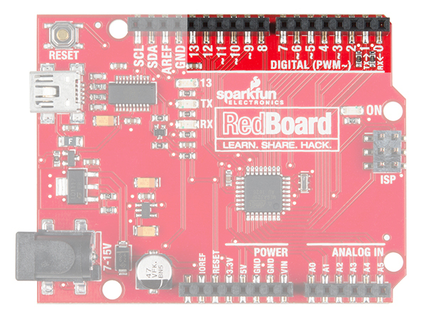
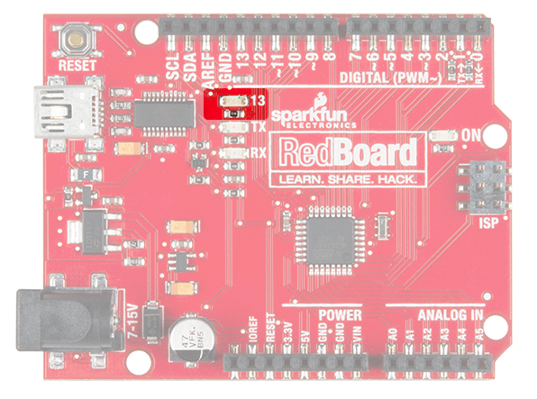
Digital Output
When working with microcontrollers such as the RedBoard, there are a variety of pins to which you can connect electronic components. Knowing which pins perform which functions is important when building your circuit. In this circuit, we will be using what is known as a digital output. There are 14 of these pins found on the RedBoard and Arduino Uno. A digital output only has two states: ON or OFF. These two states can also be thought of as HIGH or LOW or TRUE or FALSE. When an LED is connected to one of these pins, the pin can only perform two jobs: turning the LED on and turning the LED off. We'll explore the other pins and their functions in later circuits.
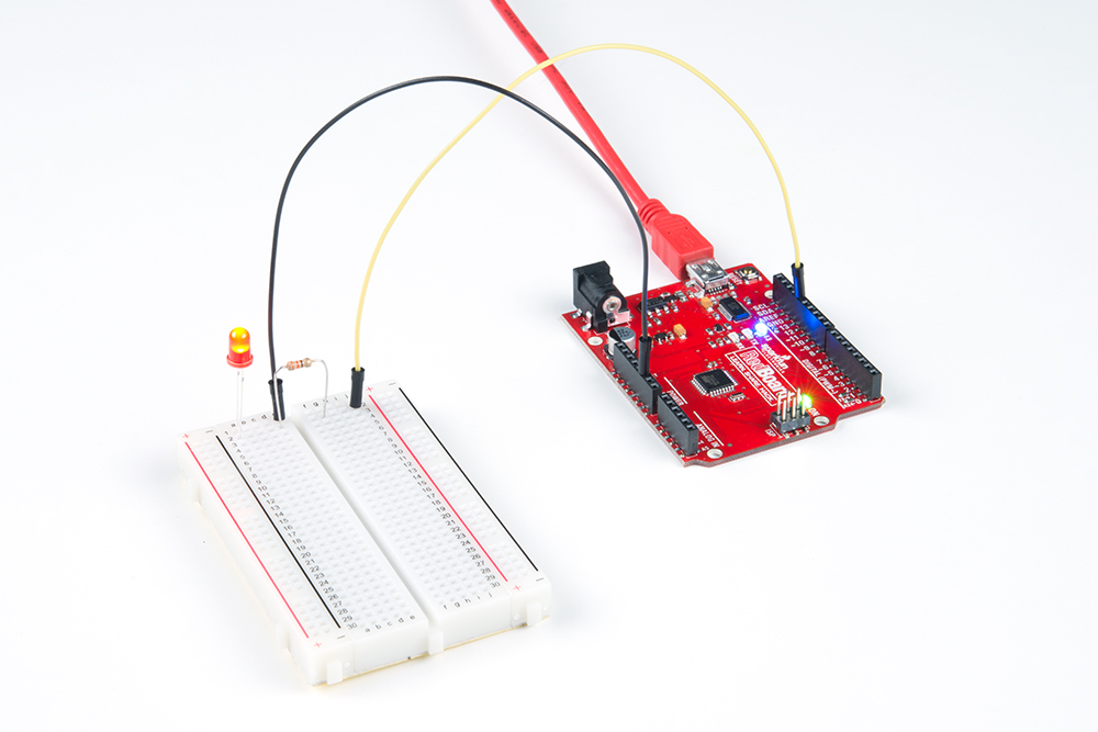
Hardware Hookup
We recommend familiarizing yourself with each of the components used in each circuit first.
| Polarized Components | Pay special attention to the component’s markings indicating how to place it on the breadboard. Polarized components can only be connected to a circuit in one direction. |
**Pay close attention to the LED. It is polarized. The negative side of the LED is the short leg, marked with a flat edge. **
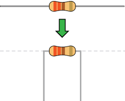
Components like resistors need to have their legs bent into 90° angles in order to correctly fit the breadboard sockets.
Ready to start hooking everything up? Check out the circuit diagram and hookup table below, to see how everything is connected.
Circuit Diagram
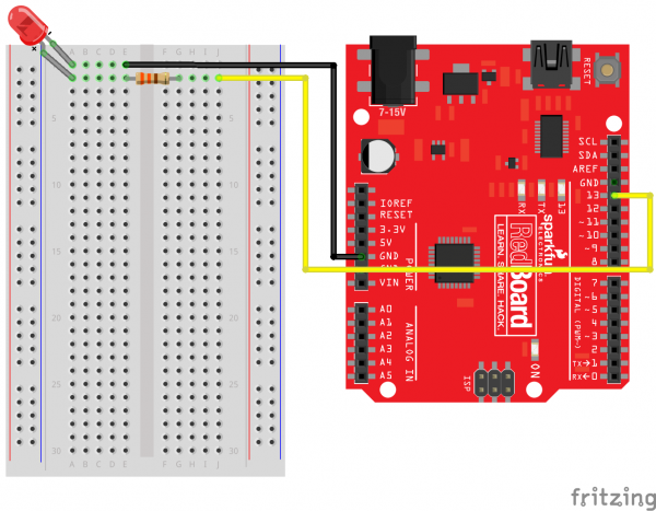
Hookup Table
| Component | RedBoard | Breadboard | Breadboard |
|---|---|---|---|
| LED | A1 LED ( - ) | A2 LED ( + ) | |
| 330Ω Resistor (orange, orange, brown) |
E2 | F2 | |
| Jumper Wire | GND | E1 | |
| Jumper Wire | Digital Pin 13 | J2 |
Open Your First Sketch
Open the Arduino IDE software on your computer.
Copy and paste the following code into the Arduino IDE. Hit upload, and see what happens!
language:cpp
/*
SparkFun Tinker Kit
Circuit 1: Blink an LED

Turns an LED connected to pin 13 on and off. Repeats forever.

This sketch was written by SparkFun Electronics, with lots of help from the Arduino community.
This code is completely free for any use.

View circuit diagram and instructions at: https://learn.sparkfun.com/tutorials/activity-guide-for-sparkfun-tinker-kit/
Download code at: https://github.com/sparkfun/SparkFun_Tinker_Kit_Code
*/

void setup() {

pinMode(13, OUTPUT);      // Set pin 13 to output

}


void loop() {

digitalWrite(13, HIGH);   // Turn on the LED

delay(2000);              // Wait for two seconds

digitalWrite(13, LOW);    // Turn off the LED

delay(2000);              // Wait for two seconds

}
What You Should See
The LED will flash on for two seconds, off for two seconds, then repeat. If it doesn't, make sure you have assembled the circuit correctly and verified and uploaded the code to your board, or see the Troubleshooting section at the end of this section.
Program Overview
- Turn the LED on by sending power to Pin 13.
- Wait 2 seconds (2000 milliseconds).
- Turn the LED off by cutting power to Pin 13.
- Wait 2 seconds (2000 milliseconds).
- Repeat.
One of the best ways to understand the code you just uploaded is to change something and see how it affects the behavior of your circuit. For this first circuit, try changing the number found in these lines of code: delay(2000);. What happens if you change both to 100? What happens if you change both to 5000? What happens if you change just one delay and not the other?
Code to Note
| Code | Description |
|---|---|
Setup and Loop:void setup(){code to run once} & void loop(){code to run forever} | Every Arduino program needs these two functions. Code that goes in between the curly brackets of setup() runs once, then the code in between the loop() curly brackets runs over and over until the RedBoard is reset or powered off. |
Input or Output?:pinMode(13, OUTPUT); | Before you can use one of the digital pins, you need to tell the RedBoard whether it is an INPUT or OUTPUT. We use a built-in "function" called pinMode() to make pin 13 a digital output. You'll learn more about digital inputs in the digital trumpet circuit. |
Digital Output:digitalWrite(13, HIGH); | When you're using a pin as an OUTPUT, you can command it to be HIGH (output 5 volts) or LOW (output 0 volts). |
Delay:delay(time in milliseconds); | Causes the program to wait on this line of code for the amount of time in between the brackets. After the time has passed, the program will continue to the next line of code. |
Comments://This is a comment | Comments are a great way to leave notes in your code explaining why you wrote it the way you did. You'll find many comments in the examples that further explain what the code is doing and why. Comments can be single line using //, or they can be multi-line using /* */. |
Coding Challenges
| Challenge | Description |
|---|---|
| Persistence of Vision | Computer screens, movies and the lights in your house all flicker so quickly that they appear to be on all of the time but are actually blinking faster than the human eye can detect. See how much you can decrease the delay time in your program before the light appears to be on all the time but is still blinking. |
| Morse Code | Try changing the delays and adding more digitalWrite() commands to make your program blink a message in Morse code. |
Troubleshooting
| Problem | Solution |
|---|---|
| I get an error when uploading my code | The most likely cause is that you have the wrong board selected in the Arduino IDE. Make sure you have selected Tools > Board > Arduino/Genuino Uno. |
| I still get an error when uploading my code | If you're sure you have the correct Board selected but you still can't upload, check that you have selected the correct Serial Port. You can change this in Tools > Serial Port > your_serial_port. |
| Which Serial Port is the right one? | Depending on how many devices you have plugged into your computer, you may have several active Serial Ports. Make sure you are selecting the correct one. A simple way to determine this is to look at your list of Serial Ports. Unplug your RedBoard from your computer. Look at the list again. Whichever Serial Port has disappeared from the list is the one you want to select once you plug your board back in to your computer. |
| My code uploads, but my LED won’t turn on | LEDs will only work in one direction. Try taking it out of your breadboard, turning it 180 degrees, and reinserting it. |
| Still not working? | Jumper wires unfortunately can go "bad" from getting bent too much. The copper wire inside can break, leaving an open connection in your circuit. If you are certain that your circuit is wired correctly and that your code is error-free and uploaded but you are still encountering issues, try replacing one or more of the jumper wires for the component that is not working. |