Adding More SERCOM Ports for SAMD Boards
 M-Short
 Introduction
SERCOM (Serial Communication) is a multiplexed serial configuration used on the SAMD21, SAMD51 and other boards. It allows you to select various serial functions for most of your pins. For example, the ATmega328 which has UART (RX/TX) on one pair of pins, I2C (SDA/SCL) on another set, and SPI (MOSI, MISO, SCK) on another set. The SAMD21 has 5 different internal ports which you can configure to use any combination of UART, I2C, and SPI. The SAMD21 and SAMD51 boards are becoming increasingly popular in part because of this feature. But how do you do it?
Required Materials
To follow along with this tutorial, you will need the following materials. You may not need everything though depending on what you have. Add it to your cart, read through the guide, and adjust the cart as necessary.
ARM-Based Microcontroller
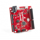
For this tutorial we are going to use the RedBoard Turbo, but you should be able to follow along just fine with any of the SAMD21 boards below (or any not listed below).
Serial Device and Prototyping Hardware
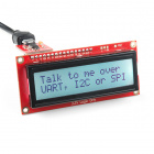
You'll also need a serial device. We will also be using a 16x2 Serial LCD Screen for our examples since it will accept commands over UART, SPI or I2C. You will need a way to connect your board to the screen as well, but those are the only components needed to follow along.


Tools
Depending on your setup, you may need a soldering iron, solder, general soldering accessories for boards without headers.


Suggested Reading
If you aren’t familiar with the following concepts, we recommend checking out these tutorials before continuing.
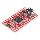
SAMD21 Mini/Dev Breakout Hookup Guide
AVR-Based Serial Enabled LCDs Hookup Guide
RedBoard Turbo Hookup Guide
A Look at the RedBoard Turbo
Whenever a new board is added to the Arduino IDE it comes with a couple of variants files (variant.h and variant.cpp). These files define which pins are being used for what. They define where D0 maps to, where the BUILT_IN_LED goes, and which pins are assigned to things like UART, I2C, etc. Pretty much any of the SAMD21 or SAMD51 boards you come across should already have at least 1 UART, I2C, and SPI port defined in their variants file. It is usually easiest to just use those. But once in a while you will want to add another port. For example, you have an accelerometer that you want to use to measure vibrations on 2 different platforms. But the accelerometer only has one available I2C address. While you could use an I2C mux, you can also just add a second I2C port to your board.
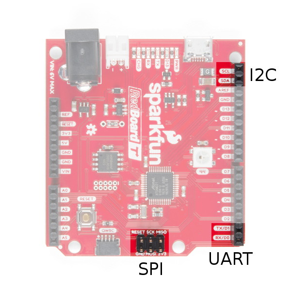
Let's take a look at the RedBoard Turbo. As you can see there is an I2C port broken out at the top right. At the bottom, you'll also see the UART broken out and the pins labeled TX and RX. Finally, you'll see what is often referred to as the legacy ISP header. Originally, this SPI port was tied to one on the side of the board (the ATMega boards only had 1 SPI port) and was used to program the bootloader onto the board. Because a lot of shields use this as the primary SPI port, this is broken out as well. However, they are located a different SPI port than the one on the side for the RedBoard Turbo.
Now let's take a closer look at the SAMD21 and start defining some terms.
- Serial -- Serial communication means one item or bit is sent at a time. This is in contrast to Parallel where multiple items are sent at once on different lines. UART, SPI, and I2C are all types of serial communication.
- UART (Universal Asynchronous Receiver/Transmitter) -- This is what is commonly referred to as serial even though it is only one type of serial. With a TX (transmit) and RX (receive) line this communication protocol does not have a clock line. Also remember that what one device is transmiting the other device is receiving so you will want to connect your TX to RX and RX to TX.
- RX -- Receive line of a UART communication.
- TX -- Transmit line of a UART communication.
- SPI (Serial Peripheral Interface) -- This serial bus has both a line for the master to send data out and the slave to receive (MOSI), one for the slave to send and the master to receive (MISO), and a clock (SCK). The CS line is used to select which board is being talked to. In other words, a bus will have 3+n wires. When a slave's CS line is selected, it knows the master is trying to talk to it. Because this is just a select line, it may or may not be included in a hardware serial interface.
- MOSI -- The master out, slave in line of an SPI bus.
- MISO -- The master in, slave out line of an SPI bus.
- SCK -- The clock line of an SPI bus.
- CS -- The cable select line of an SPI bus. Also, called slave select (SS).
- I2C (or I2C, Inter-Integrated Circuit) -- This is a 2 wire serial interface that uses a clock and data line to pass information. Each device on the bus has a different address which the master will specifiy during communication. I2C buses require pull-up resistors on both lines. Most SparkFun I2C boards have the pull-up resistors built in as well as a solder jumper to disable them.
- SDA -- This is the data line of an I2C bus.
- SCL -- This is the clock line of an I2C bus.
- SERCOM (Serial Communications) -- This is a the name of a serial communications port on the SAMD21 boards. Because of the SAMD21's pin multiplexing, each pin on the chip has multiple function. Therefore, each SERCOM port can use various pins.
- Port
- SERCOM Port -- The SAMD21 has 6 Serial Communication modules what can be configured in various ways. A port or module refers to one of them. This gives us 6 different communications options. Most of the SAMD21 boards use 4-5 of these to bring you 1 SPI, UART, and I2C bus and often use 1 or 2 more for a second SPI, and/or connecting to another chip on the board such as onboard flash or a WiFi module.
- Pad -- Each SERCOM Port will have 4 pads (0-4). In order to determine how to use a SERCOM port, we will need to figure out which pins are on which pads of our port. This is written in a variety of ways, for example pad 0 on SERCOM 1 may be written as SERCOM1/Pad[0], SERCOM1.0, or even 1:0.
- SAMD21 Port -- While Arduino gives names to all usable pins (often based on how they are configured) the chip manufacture does not assign pin numbers in such a way. Instead each pin has a port name. In the case of the SAMD21, the port names will have a letter (either A or B) and a number and look like this: PortA10, PortB08. Often for the sake of room, the Port will be abbreviated to the letter 'P' and the names will look like this: PA10, PB08, etc.
- Macro -- This is a predefined value in your code. Usually designated by the
#definecommand. When looking at board definitions, you will see a lot of macros that have definitions defined elsewhere. The definitions are not as important and understanding what the macro is filling in for. For example, the macroPIN_WIRE_SDAis being used to define which pin you are using for SDA on a Wire (I2C) interface. - Multiplex (or mux for short) -- This is the practice of assigning many conflicting attributes to 1 item and being able to select which one you want. In this case, each pin on the SAMD21 chip is assigned many functions from analog inputs, to digital inputs, to timers, to various SERCOM ports. As we set up a SERCOM port we will need to spend some time selecting the correct feature in our mux.
- Qwiic -- Qwiic is SparkFun's I2C interface. Get it, QwIIC! This port connects to a board I2C port as well as providing power (3.3V). You will see it on quite a few boards including the Redboard Turbo. This is hard wired into the board's SDA and SCL pins so you can't change it.
Datasheets - SAMD21
Graphical Datasheet
Part of the trick of setting up SERCOM Ports is determining which pins go together. You can't just assign them Willy Nilly. The SparkFun graphical datasheets do a pretty good job of summarizing them. We are going to start by looking at the Redboard Turbo and checking its graphical datasheet as well as the SAMD21 datasheet.
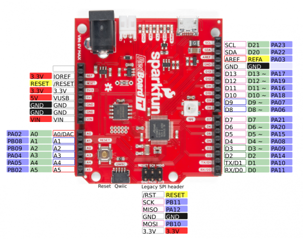
The SparkFun graphical datasheets are great at giving you a quick one page overview of the features of your board. Above you see a simplified version of the Graphical Datasheet for the Redboard Turbo. Click on it and you'll get a full size version complete with all the SERCOM ports listed. As you can see the Turbo has 1x Serial port, 1x I2C port (which is also connected to the Qwiic connector) and 1x SPI ports (the legacy ISCP header).
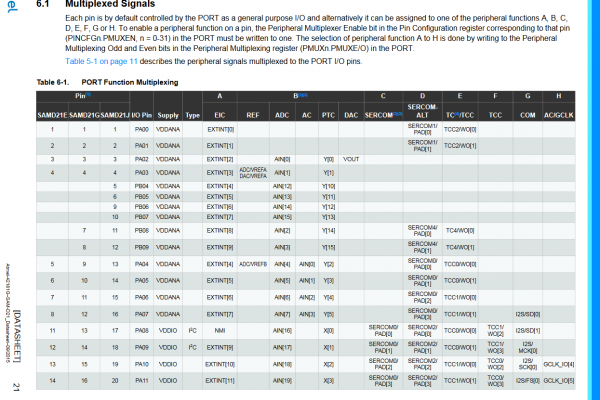
SAMD21 Datasheet
Looking at the SAMD21 datasheet (page 21) under I/O Multiplexing and Considerations, we can start to see all the options each pin can have. We can select any of the columns for each pin. Specifically, we are looking at columns C and D. Also, it is worth noting that the chip on the Redboard Turbo is the SAMD21G18. As you can see there are other SAMD21 chip variants that have more or less pins. The 'G' version is the one we want. As you can see, many of the pins have a 1 or 2 SERCOM ports available.
But What Pin Corresponds Where?
While you can check the schematic/board file to see what pin on the chip goes where, the best option is probably the variant.cpp file for your board. Let's look at this file defined for the RedBoard Turbo. The file starts with a pretty large comment. While this is a good reference, keep in mind that people may choose not to update the comment for their board. Under the comment, you should see the Pin Descriptions. On the RedBoard Turbo, the pin definitions are broken out into sections to make it easier to read. The first section is D0-D13 staring with D0 and D1 which are the UART pins. You'll notice that the first arguments list the port and the pin on that port. The comment at the end also tells you what SERCOM port is being used. If we scroll through and find the pins that are using SERCOM pins, we'll find the following.
language:c
// 0..13 - Digital pins
// ----------------------
// 0/1 - SERCOM/UART (Serial1)
{ PORTA, 11, PIO_SERCOM, (PIN_ATTR_DIGITAL), No_ADC_Channel, NOT_ON_PWM, NOT_ON_TIMER, EXTERNAL_INT_11 }, // RX: SERCOM0/PAD[3]
{ PORTA, 10, PIO_SERCOM, (PIN_ATTR_DIGITAL), No_ADC_Channel, NOT_ON_PWM, NOT_ON_TIMER, EXTERNAL_INT_10 }, // TX: SERCOM0/PAD[2]

// 20..21 I2C pins (SDA/SCL and also EDBG:SDA/SCL)
// ----------------------
{ PORTA, 22, PIO_SERCOM, PIN_ATTR_DIGITAL, No_ADC_Channel, NOT_ON_PWM, NOT_ON_TIMER, EXTERNAL_INT_6 }, // SDA: SERCOM3/PAD[0]
{ PORTA, 23, PIO_SERCOM, PIN_ATTR_DIGITAL, No_ADC_Channel, NOT_ON_PWM, NOT_ON_TIMER, EXTERNAL_INT_7 }, // SCL: SERCOM3/PAD[1]

// 22..24 - SPI pins (ICSP:MISO,SCK,MOSI)
// ----------------------
{ PORTA, 12, PIO_SERCOM_ALT, PIN_ATTR_DIGITAL, No_ADC_Channel, NOT_ON_PWM, NOT_ON_TIMER, EXTERNAL_INT_12 }, // MISO: SERCOM4/PAD[0]
{ PORTB, 10, PIO_SERCOM_ALT, PIN_ATTR_DIGITAL, No_ADC_Channel, NOT_ON_PWM, NOT_ON_TIMER, EXTERNAL_INT_10 }, // MOSI: SERCOM4/PAD[2]
{ PORTB, 11, PIO_SERCOM_ALT, PIN_ATTR_DIGITAL, No_ADC_Channel, NOT_ON_PWM, NOT_ON_TIMER, EXTERNAL_INT_11 }, // SCK: SERCOM4/PAD[3]

// 30..41 - Extra Pins
// ----------------------
// 30/31 - Extra UART
{ PORTB, 22, PIO_SERCOM_ALT, PIN_ATTR_NONE, No_ADC_Channel, NOT_ON_PWM, NOT_ON_TIMER, EXTERNAL_INT_NONE }, // 30/TX: SERCOM5/PAD[2]
{ PORTB, 23, PIO_SERCOM_ALT, PIN_ATTR_NONE, No_ADC_Channel, NOT_ON_PWM, NOT_ON_TIMER, EXTERNAL_INT_NONE }, // 31/RX: SERCOM5/PAD[3]

// 32/33 I2C (SDA/SCL and also EDBG:SDA/SCL)
{ PORTA, 22, PIO_SERCOM, PIN_ATTR_NONE, No_ADC_Channel, NOT_ON_PWM, NOT_ON_TIMER, EXTERNAL_INT_NONE }, // SDA: SERCOM3/PAD[0]
{ PORTA, 23, PIO_SERCOM, PIN_ATTR_NONE, No_ADC_Channel, NOT_ON_PWM, NOT_ON_TIMER, EXTERNAL_INT_NONE }, // SCL: SERCOM3/PAD[1]

// 34..37 - EDBG/SPI
{ PORTA, 19, PIO_SERCOM, PIN_ATTR_NONE, No_ADC_Channel, NOT_ON_PWM, NOT_ON_TIMER, EXTERNAL_INT_NONE }, // D12/MISO: SERCOM1/PAD[3]
{ PORTA, 16, PIO_SERCOM, PIN_ATTR_NONE, No_ADC_Channel, NOT_ON_PWM, NOT_ON_TIMER, EXTERNAL_INT_NONE }, // D11/MOSI: SERCOM1/PAD[0]
{ PORTA, 18, PIO_SERCOM, PIN_ATTR_NONE, No_ADC_Channel, NOT_ON_PWM, NOT_ON_TIMER, EXTERNAL_INT_NONE }, // D10/SS: SERCOM1/PAD[2]
{ PORTA, 17, PIO_SERCOM, PIN_ATTR_NONE, No_ADC_Channel, NOT_ON_PWM, NOT_ON_TIMER, EXTERNAL_INT_NONE }, // D13/SCK: SERCOM1/PAD[1]
Based on the code it looks like we are using SERCOM 0, 1, 3, 4, and 5. Any extra ports we use are going to have to use either SERCOM ports that are not already used or reuse one that is. Also, keep in mind that often unused ports are not removed. For example, this file lists D30 and D31 as an extra serial UART port. But, the board doesn't breakout D30 and D31 (but the SAMD21 development board did) so SERCOM 5 is actually free as well.
Steps to Add a SERCOM Port
We basically have 4x steps we are going to follow for each type of port we are going to add. The steps are the same for all types, but they are implemented a bit differently. Because the charts and datasheets are used for each type, they are listed at the end of the document. Make sure to have an extra window open when referencing the pins.
1.) Figure out which pins to use.
2.) Add your code.
3.) Update the pin definitions based on the pin mux.
4.) Putting it all together.
Adding a UART
1.) Figure Out Which Pins to Use.
Let's start by checking out the SERCOM.h file in Arduino's SAMD21 core files. Specifically, we are looking at lines 73-86. You should see the code listed below. But what does it mean? There are 2 parts, the first part defines which pads you can use for an RX pad. It looks like you can use pads 0, 1, 2, and 3 which is all of them. Next, it defines which pads you can use for TX. It looks like you can only use pads 0 and 2. So, we'll need to keep that in mind when we select our pins.
language:c
typedef enum
{
    SERCOM_RX_PAD_0 = 0,
    SERCOM_RX_PAD_1,
    SERCOM_RX_PAD_2,
    SERCOM_RX_PAD_3
} SercomRXPad;

typedef enum
{
    UART_TX_PAD_0 = 0x0ul,  // Only for UART
    UART_TX_PAD_2 = 0x1ul,  // Only for UART
    UART_TX_RTS_CTS_PAD_0_2_3 = 0x2ul,  // Only for UART with TX on PAD0, RTS on PAD2 and CTS on PAD3
} SercomUartTXPad;
Since none of the boards I've come across use SERCOM 2 for anything, we're going to use it for our examples. Let's start with TX since those pins are limited compared to the RX. We'll need to find which pins are on 2:0 or 2:2. Looking at our charts, you can see those pins are labeled as MISO, D4, D2, and D1/TX. Since MISO and D1/TX are already being used, that means we can use D2 or D4. Let's use D2 and see if we can put our new serial port right next to the original one. That means that RX should be on D3. It looks like D3 is on 2:1 so that will work.
2.) Add Your Code.
Next, lets figure out what code we need. Let's take a look at the variant.cpp file again. Near the bottom, you'll see the following lines. This is what we are trying to duplicate in our code. The variant.h file defines all those macros, but their names give us a good idea of what should go there.
language:c
Uart Serial1( &sercom0, PIN_SERIAL1_RX, PIN_SERIAL1_TX, PAD_SERIAL1_RX, PAD_SERIAL1_TX ) ;
Uart Serial( &sercom5, PIN_SERIAL_RX, PIN_SERIAL_TX, PAD_SERIAL_RX, PAD_SERIAL_TX ) ;
void SERCOM0_Handler()
{
  Serial1.IrqHandler();
}

void SERCOM5_Handler()
{
  Serial.IrqHandler();
}
Let's start with the definition. Let's pick a name. "mySerial" sounds good. We also know we are going to use SERCOM 2, that RX will be on D3, TX on D2, and that D3 uses pad 1, and D2 uses pad 2. So we'll add the following to our code.
language:c
Uart mySerial(&sercom2, 3, 2, SERCOM_RX_PAD_1, UART_TX_PAD_2);

void SERCOM2_Handler()
{
  mySerial.IrqHandler();
}
3.) Update the Pin Definitions Based on the Pin Mux.
Next, we need to set up the mux. Right now, D2 and D3 are defined as general I/O pins. We want them to act as SERCOM pins. The first thing we need to do is to add the pin peripheral library. Then we use the pinPeripheral commands to set up the pin definition.
language:c
#include "wiring_private.h" // pinPeripheral() function

pinPeripheral(2, PIO_SERCOM);
pinPeripheral(3, PIO_SERCOM_ALT);
You'll notice that one uses the argument PIO_SERCOM and the other PIO_SERCOM_ALT. If you look on the datasheet, you'll notice that pins can have a SERCOM port listed under SERCOM or SERCOM-ALT. For D2, we are using the SERCOM port in the SERCOM column. For D3, we are using the SERCOM port in the SERCOM-ALT column.
4.) Putting It All Together.
Step 4 is running the code, testing, and troubleshooting. For this example, we are going to grab a serial LCD screen and connect it to our new serial UART port. Make sure that you have soldered headers to the LCD if you have not already.

The next step is to test out the UART port with the code listed below. The code is pretty bare bones and shows you where all your new code should go. Copy and paste the code in your Arduino IDE. Select your board, COM port, and hit upload.
language:c
/*********************************************************************
 * Sample code for setting up additional Serial ports on a SamD21 board
 * In this example the Redboard Turbo is used with the 16x2 SerLCD display
 * For more information on the SerLCD code check out the github repo
 * https://github.com/sparkfun/OpenLCD
 * https://www.sparkfun.com/products/14812
 * https://www.sparkfun.com/products/14072
 * By: Michelle Shorter - SparkFun Electronics
 * License: This code is public domain but you buy me a burger
 * if you use this and we meet someday (Beefware license).
 *********************************************************************/

#include "wiring_private.h" // pinPeripheral() function
//D2-TX, D3-RX
Uart mySerial (&sercom2, 3, 2, SERCOM_RX_PAD_1, UART_TX_PAD_2);
void SERCOM2_Handler()
{
  mySerial.IrqHandler();
}

int i = 0;

void setup() {
  // put your setup code here, to run once:
  mySerial.begin(9600);

  pinPeripheral(2, PIO_SERCOM);
  pinPeripheral(3, PIO_SERCOM_ALT);

  mySerial.write('|');//Setting character
  mySerial.write('-');//Clear display
  mySerial.write('|');//Put LCD into setting mode
  mySerial.write(158 + 0); //Set green backlight amount to 0%
  mySerial.write('|');//Put LCD into setting mode
  mySerial.write(188 + 0); //Set blue backlight amount to 0%
  mySerial.write('|');//Put LCD into setting mode
  mySerial.write(128 + 29); //Set white/red backlight amount to 51% (100%=+29)

  mySerial.print("Welcome");
  delay(1000);
}

void loop() {
  // put your main code here, to run repeatedly:
  mySerial.write('|');//Setting character
  mySerial.write('-');//Clear display
  mySerial.print("Counting ");
  mySerial.print(i);
  i++;
  delay(1000);

}
Adding an SPI
1.) Figure Out Which Pins to Use.
Let's start by checking out the SERCOM.h file in Arduino’s SAMD21 core files. Specifically we are looking at lines 73-79 (yep, we looked at those when we added the UART) and lines 102-108. You should see the code listed below. But what does it mean? There are 2 parts, the first part defines which pads you can use for an RX (MISO) pad. It looks like you can use pads 0, 1, 2, and 3 which is all of them. Next, it defines which pads you can use for TX (MOSI, and SCK) and in what configuration. So, we'll need to keep that in mind when we select our pins.
language:c
typedef enum
{
    SERCOM_RX_PAD_0 = 0,
    SERCOM_RX_PAD_1,
    SERCOM_RX_PAD_2,
    SERCOM_RX_PAD_3
} SercomRXPad;

//...

typedef enum
{
    SPI_PAD_0_SCK_1 = 0,
    SPI_PAD_2_SCK_3,
    SPI_PAD_3_SCK_1,
    SPI_PAD_0_SCK_3
} SercomSpiTXPad;
Since none of the boards I've come across use SERCOM 2 for anything we're going to use it for our examples. Let's start with our outputs since those pins are limited compared to the MISO pins. It looks like SCK can only be on pad 1 or 3, and MOSI can be on 0, 2, or 3 depending on the configuration. So, looking at our table, let's start by removing the pins that are not broken out to our board or already in use. That removes MISO, D38, D1/TX, and D0/RX, leaving use with D4, D3, D2, and D5. Any of those look like good options, but lets go with D3 for MISO, D5 for SCK, and D4 for MOSI. Again, we'll need to dig into our fancy charts to figure out what is where.
2.) Add Your Code.
Next lets figure out what code we need. Let's take a look at the SPI.cpp file again. All the way near the bottom on line 261, you'll see the following line. This is what we are trying to duplicate in our code. The variant.h file defines all those macros, but their names give us a good idea of what should go there.
language:c
 SPIClass SPI (&PERIPH_SPI, PIN_SPI_MISO, PIN_SPI_SCK, PIN_SPI_MOSI, PAD_SPI_TX, PAD_SPI_RX);
Let's start with the definition. Let's pick a name. "SPI2" sounds good. We also know we are going to use SERCOM 2, that we are going to use D3 for MISO, D5 for SCK, and D4 for MOSI. So, we'll add the following to our code.
language:c
SPIClass SPI2 (&sercom2, 3, 5, 4, SPI_PAD_0_SCK_3, SERCOM_RX_PAD_1);
3.) Update the Pin Definitions Based on the Pin Mux.
Next, we need to set up the mux. Right now, the pins are defined as general I/O pins. We want them to act as SERCOM pins. The first thing we need to do is to add the pin peripheral library. Then we use the pinPeripheral command to set up the pin defintion.
language:c
#include "wiring_private.h" // pinPeripheral() function

SPI2.begin();
pinPeripheral(3, PIO_SERCOM_ALT);
pinPeripheral(4, PIO_SERCOM_ALT);
pinPeripheral(5, PIO_SERCOM);
You'll notice that one uses the argument PIO_SEROM and the others PIO_SERCOM_ALT. If you look on the datasheet, you'll notice that pins can have a SERCOM port listed under SERCOM or SERCOM-ALT. For D5, we are using the SERCOM port in the SERCOM column. For D3 and D4, we are using the SERCOM port in the SERCOM-ALT column.
4.) Putting It All Together.
Step 4 is running the code, testing, and troubleshooting. For this example, we are going to grab a Serial LCD screen and connect it to our new SPI port. Make sure that you have soldered headers to the LCD if you have not already.

The next step is to test out the SPI port with the code listed below. The code is pretty bare bones and shows you where all your new code should go. The code also includes a pin definition for the CSPIN. Copy and paste the code in your Arduino IDE. Select your board, COM port, and hit upload.
language:c
/*********************************************************************
   Sample code for setting up additional Serial ports on a SamD21 board
   In this example the Redboard Turbo is used with the 16x2 SerLCD display
   For more information on the SerLCD code check out the github repo
   https://github.com/sparkfun/OpenLCD
   https://www.sparkfun.com/products/14812
   https://www.sparkfun.com/products/14072
   By: Michelle Shorter - SparkFun Electronics
   License: This code is public domain but you buy me a burger
   if you use this and we meet someday (Beefware license).
**********************************************************************/
#include <SPI.h>
#include "wiring_private.h" // pinPeripheral() function
#define CSPIN 6
#define Time 25

//D3-MISO, D4-MOSI, D5-SCK
SPIClass SPI2 (&sercom2, 3, 5, 4, SPI_PAD_0_SCK_3, SERCOM_RX_PAD_1);

int i = 0;
void setup() {
  // put your setup code here, to run once:

  //Get all pins and SPI ports setup
  SPI2.begin();
  pinPeripheral(3, PIO_SERCOM_ALT);
  pinPeripheral(4, PIO_SERCOM_ALT);
  pinPeripheral(5, PIO_SERCOM);
  pinMode(CSPIN, OUTPUT);
  digitalWrite(CSPIN, HIGH); //make sure it is high to start
  SPI2.setClockDivider(SPI_CLOCK_DIV128); //Slow down the master a bit

  //Reset the screen, set backlight, etc.
  digitalWrite(CSPIN, LOW);// Select the screen before sending
  SPI2.transfer('|');//Setting character
  SPI2.transfer('-');//Clear display
  SPI2.transfer('|');//Put LCD into setting mode
  SPI2.transfer(158 + 0); //Set green backlight amount to 0%
  SPI2.transfer('|');//Put LCD into setting mode
  SPI2.transfer(188 + 10); //Set blue backlight amount to 0%
  SPI2.transfer('|');//Put LCD into setting mode
  SPI2.transfer(128 + 5); //Set white/red backlight amount to (15=51% 100%=+29)
  delay(Time);
  digitalWrite(CSPIN, HIGH);// Deselect the screen after sending
  delay(1000);//Each setting change prints an output, this delay allows them to be printed before trying to keep going

  //Send Welcome Text
  char tempString[50]; //Needs to be large enough to hold the entire string with up to 5 digits
  sprintf(tempString, "Welcome ");
  spiSendString(tempString);
  delay(1500);
}

void loop() {
  // put your main code here, to run repeatedly:

  //Clear the screen, then send the Counting string
  digitalWrite(CSPIN, LOW);// Select the screen before sending
  SPI2.transfer('|');//Setting character
  SPI2.transfer('-');//Clear display
  delay(Time);
  digitalWrite(CSPIN, HIGH);// Deselect the screen after sending
  char tempString[50]; //Needs to be large enough to hold the entire string with up to 5 digits
  sprintf(tempString,"Counting: %d ", i);
  spiSendString(tempString);
  i++;
  delay(1000-Time);

}

//Sends a string over SPI
void spiSendString(char* data)
{
  digitalWrite(CSPIN, LOW); //Drive the CS pin low to select OpenLCD
  for(byte x = 0 ; data[x] != '\0' ; x++) //Send chars until we hit the end of the string
    SPI2.transfer(data[x]);
  digitalWrite(CSPIN, HIGH); //Release the CS pin to de-select OpenLCD
}
Adding an I2C
1.) Figure Out Which Pins to Use.
Picking pins for I2C is a bit easier. SDA is always on Pad 0. SCL is always on Pad 1. That's it. In this case, when we look at our chart, we can immediately rule out MISO and D38 as those pins are used or not broken out. That means that D4 will be SDA and D3 will be SCL.
2.) Add Your Code.
Next, let's figure out what code we need. Let's take a look at the Wire.cpp file in Arduino’s SAMD21 core files. All the way near the bottom on line 285, you'll see the following line. This is what we are trying to duplicate in our code. The variant.h file defines all those macros, but their names give us a good idea of what should go there.
language:c
TwoWire Wire(&PERIPH_WIRE, PIN_WIRE_SDA, PIN_WIRE_SCL);
Let's start with the definition. Let's pick a name. "myWire" sounds good. We also know we are going to use SERCOM 2, that we are going to use D4 for SDA and D3 for SCL. So, we'll add the following to our code.
language:c
TwoWire myWire(&sercom2, 4, 3);
3.) Update the Pin Definitions Based on the Pin Mux.
Next, we need to set up the mux. Right now the pins are defined as general I/O pins. We want them to act as SERCOM pins. The first thing we need to do is to add the pin peripheral library. Then we use the pinPeripheral command to set up the pin definition.
language:c
#include "wiring_private.h" // pinPeripheral() function

myWire.begin();
pinPeripheral (4,PIO_SERCOM_ALT);
pinPeripheral (3,PIO_SERCOM_ALT);
You'll notice that the code uses the argument PIO_SERCOM_ALT. If you look on the datasheet, you'll notice that pins can have a SERCOM port listed under SERCOM or SERCOM-ALT. In this case, both pins are under the SERCOM_ALT column, but if you are using a pin under the SERCOM column, use the argument "PIO_SEROM".
4.) Putting It All Together.
Step 4 is running the code, testing, and troubleshooting. For this example, we are going to grab a Serial LCD screen and connect it to our new I2C port. Make sure that you have soldered headers to the LCD if you have not already.
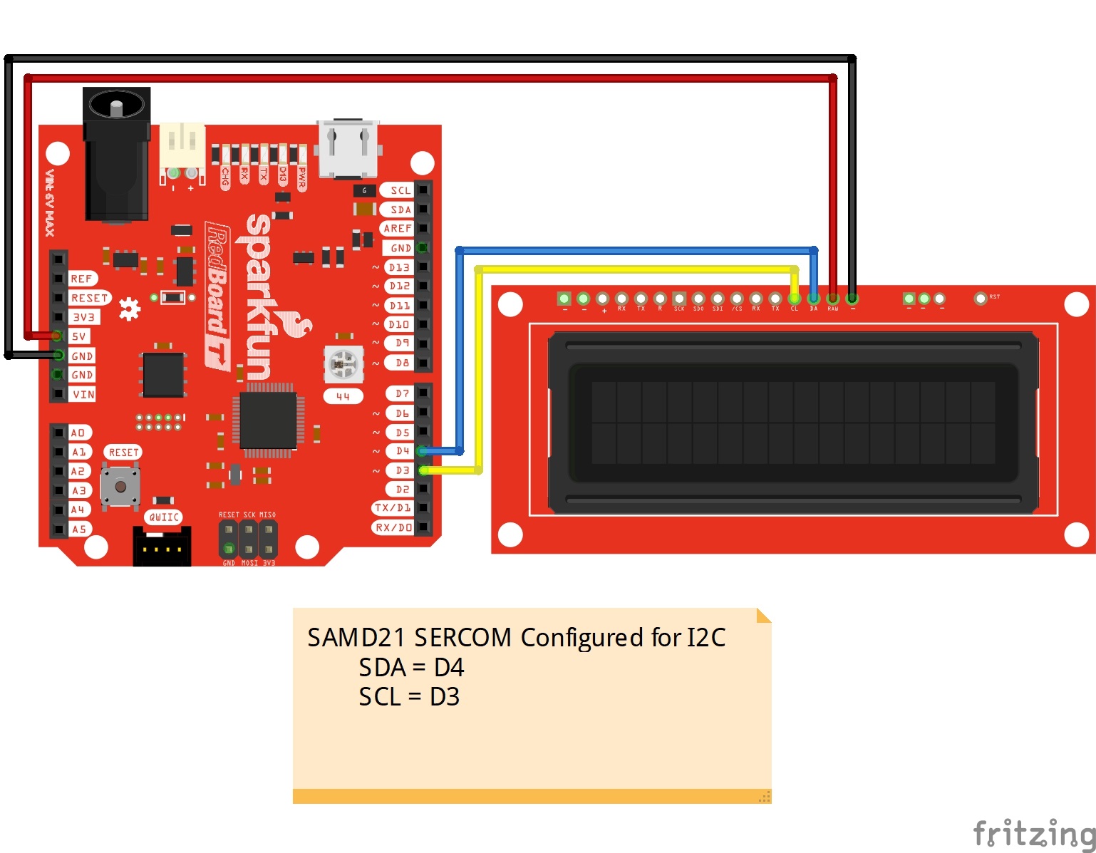
The next step is to test out the I2C port with the code listed below. The code is pretty bare bones and shows you where all your new code should go. Copy and paste the code in your Arduino IDE. Select your board, COM port, and hit upload.
language:c
/*********************************************************************
   Sample code for setting up additional Serial ports on a SamD21 board
   In this example the Redboard Turbo is used with the 16x2 SerLCD display
   For more information on the SerLCD code check out the github repo
   https://github.com/sparkfun/OpenLCD
   https://www.sparkfun.com/products/14812
   https://www.sparkfun.com/products/14072
   By: Michelle Shorter - SparkFun Electronics
   License: This code is public domain but you buy me a burger
   if you use this and we meet someday (Beefware license).
**********************************************************************/
#include <Wire.h>
#include "wiring_private.h" // pinPeripheral() function

//D4 SDA, D3 SCL
TwoWire myWire(&sercom2, 4, 3);

#define DISPLAY_ADDRESS1 0x72 //This is the default address of the OpenLCD

int i = 0;
void setup() {
  // put your setup code here, to run once:

  //Get all pins and I2C ports setup

  myWire.begin();
  pinPeripheral(3, PIO_SERCOM_ALT);
  pinPeripheral(4, PIO_SERCOM_ALT);

  //Reset the screen, set backlight, etc.
  myWire.beginTransmission(DISPLAY_ADDRESS1);
  myWire.write('|');//Setting character
  myWire.write('-');//Clear display
  myWire.write('|');//Put LCD into setting mode
  myWire.write(158 + 0); //Set green backlight amount to 0%
  myWire.write('|');//Put LCD into setting mode
  myWire.write(188 + 15); //Set blue backlight amount to 0%
  myWire.write('|');//Put LCD into setting mode
  myWire.write(128 + 0); //Set white/red backlight amount to (15=51% 100%=+29)
  //Send Welcome Text
  myWire.print("Welcome ");
  myWire.endTransmission();
  delay(3000);
}

void loop() {
  // put your main code here, to run repeatedly:

  //Clear the screen, then send the Counting string
  myWire.beginTransmission(DISPLAY_ADDRESS1);
  myWire.write('|');//Setting character
  myWire.write('-');//Clear display
  myWire.print("Counting: ");
  myWire.print(i);
  myWire.endTransmission();
  i++;
  delay(1000);

}
Helpful Charts
I promised you some charts.
- Let's start with the SAM21 datasheet. Starting on page 21 under I/O Multiplexing and Considerations, you'll see all the pin definition including the mux options. This is really where everything comes from.
- Next are the graphical datasheets. While these are available on the product pages of any board that has one, here they are as a neat little collection.
Now here are a few charts I made to help you out...
Arduino Pins on SAMD21
| SERCOM | Port 0 | Port 0 Alt | Port 1 | Port 1 Alt | Port 2 | Port 2 Alt | Port 3 | Port 3 Alt |
|---|---|---|---|---|---|---|---|---|
| 0 | D4 | A3 | D3 | A4 | D1 | D8 | D0 | D9 |
| 1 | D11 | Crystal | D13 | Crystal | D10 | SWCLK | D12, RXLED |
SWDIO |
| 2 | MISO | D4 | D38 | D3 | D2 | D1/TX | D5 | D0/RX |
| 3 | D20/SDA | D11/MOSI | D21/SCL | D13/SCK | USB | D10/SS, D6 |
USB | D12/MISO, D7 |
| 4 | A1, MISO |
A2, D38 |
MOSI, D2 |
SCK, D4 |
||||
| 5 | D20/SDA, A5 |
D21/SCL | D6 | USB, EDBGTX |
D7 | USB, EDBGRX |
Note: The ISP header does not name the pins individually so it is referred to as ISP or the actual SPI pin names that are used on the board.
Note: A comma means there are 2 pins that can use that port. A slash denotes 2 different names for the same pin.
Note: Some pins are tied directly to the USB port or the Crystal and not available for use. They are labeled as such.
Arduino Boards
I also figured it might be nice to know which SERCOM ports are open on different Arduino boards. Below is a table that lists what SERCOM ports that are already assigned to a serial protocol for a few development boards.
| SERCOM Port | 0 | 1 | 2 | 3 | 4 | 5 |
|---|---|---|---|---|---|---|
| Zero | Serial1 | SPI | I2C | ISP | Serial on EDBG | |
| MKR1000 | I2C | SPI | WinC1500 (SPI) | Serial1 | ||
| SAMD21 Development Board | Serial1 | SPI | I2C | ISP | Serial | |
| SAMD21 Mini Board | Serial1 | SPI | I2C | |||
| RedBoard Turbo | Serial1 | SPI | I2C | ISP | Flash |
Resources and Going Further
For more information, check out the resources below:
Need some inspiration for your next project? Check out some of these related tutorials: