ADXL337 and ADXL377 Accelerometer Hookup Guide
 JordanDee
Example Hookup
Soldering
Before you can plug your accelerometer breakout board into a breadboard and connect it to anything, you'll need to solder connectors or wires to the breakout pins. What you solder to the board depends on how you're going to use it.
If you're going to use the breakout board in a breadboard or similar 0.1"-spaced perfboard, we recommend soldering straight male headers into the pins (there are also long headers if you need).
If you're going to mount the breakout into a tight enclosure, you may want to solder wires (stranded or solid-core) directly into the pins.
Simple Hookup
This example will use an Arduino Uno to collect and interpret the sensor data from the ADXL337 or ADXL377. Since the sensors' outputs are analog, all we need are three wires between the Arduino's 'Analog In' pins and accelerometer (aside from power and ground). While the following hookup diagram shows the ADXL337, the header and connections to the Arduino are the same for both boards. Here's the hookup:
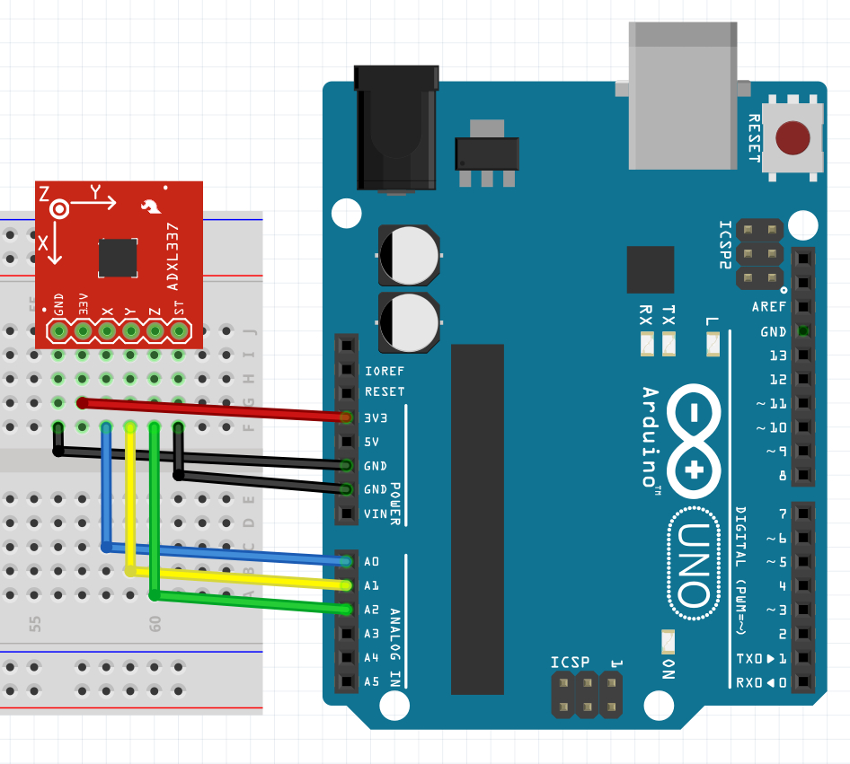
We simply have to supply the accelerometer with power (3.3V and GND), then hookup the X, Y, and Z lines of the sensor to ADC pins (A0, A1, and A2 respectively in this case). The self test pin (ST) can be left disconnected or connected to ground under normal operation. If you want to use the self test to double check the functionality of the sensor, tie it to 3.3V. Check the datasheet for more info.