ADXL345 Hookup Guide
 TheDarkSaint
Assembly
With the ADXL345, I2C and SPI digital communications are available. In both cases, the ADXL345 operates as a slave device.
Note: A potential problem when hooking up the ADXL345 breakout to an Arduino (or compatible board) is, if you are using a breadboard with loosely connected jumper wires, you risk getting bad data. Make sure your connections are solid, and you should be fine.
SPI Communication
First, we will look at how to connect an Arduino (or compatible board like SparkFun's RedBoard) to the ADXL345 breakout board for SPI communication.
In SPI mode, the CS pin is controlled by the bus master. For SPI, either 3- or 4- wire configuration is possible.
Note: When using 3-wire SPI, it is recommended that the SDO pin be pulled up to VDD I/O or pulled down to GND via a 10 kΩ resistor. Please refer to page 15 of the ADXL345 Datasheet for additional information.
The following is a table describing which pins on the Arduino should be connected to the pins on the accelerometer for SPI 4-wire communication.
| Arduino Pin | ADXL345 Pin |
| GND | GND |
| 3V3 | VCC |
| 10 | CS |
| 12 | SDO |
| 11 | SDA |
| 13 |
SCL |
Here is a wiring connection diagram to aid you in hooking it up for SPI 4-wire communication.

I2C Communication
Now, let's look at how to connect an Arduino (or compatible board like SparkFun's RedBoard) to the ADXL345 breakout board for I2C communication.
I2C mode is enabled if the CS pin is tied to high. There is no default mode if the CS pin is left unconnected, so it should always be tied high or driven by an external controller.
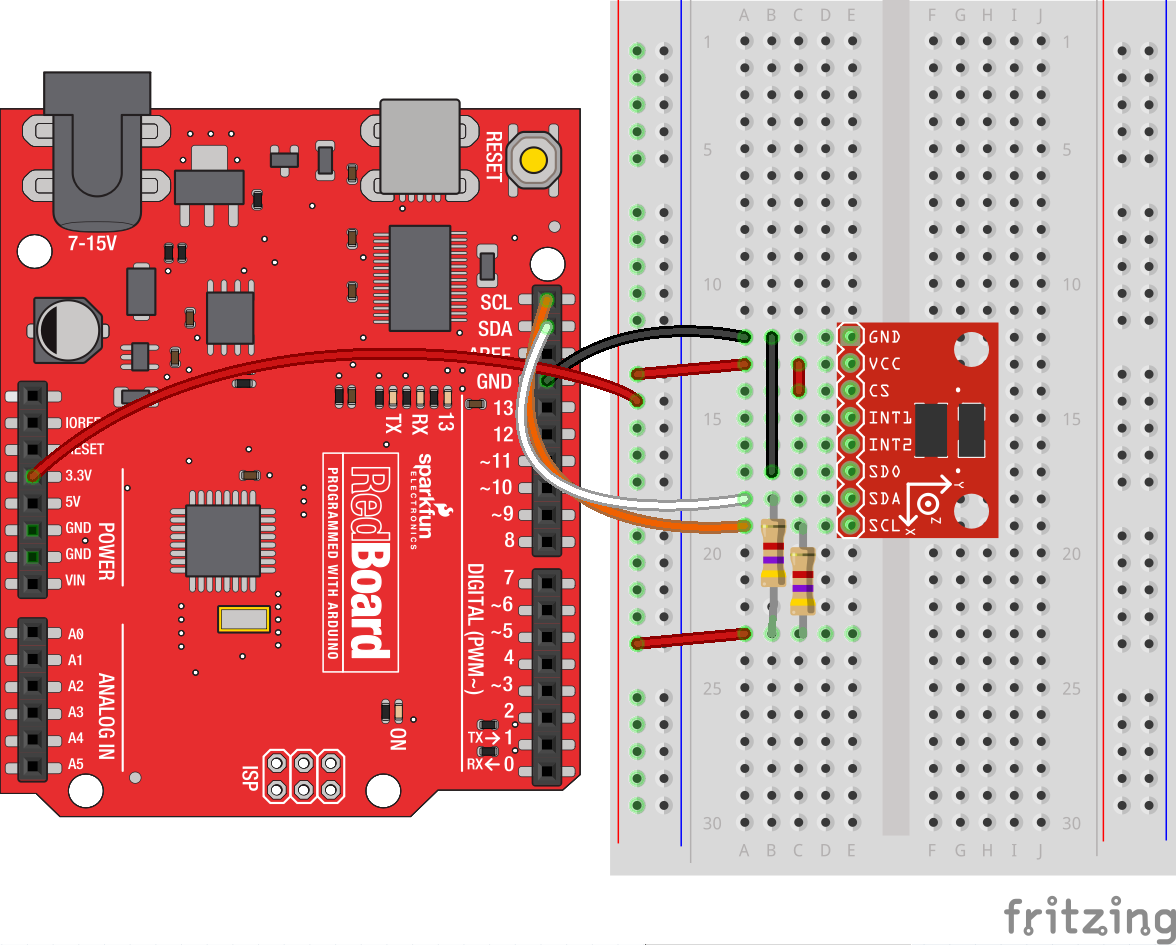
Note: If other devices are connected to the same I2C bus, the nominal operating voltage level of those other devices cannot exceed VDD I/O by more than 0.3 V. External pull-up resistors are necessary for proper I2C operation. Used in this connection diagram are two 4.7 kΩ resistors. Please refer to page 18 of the ADXL345 Datasheet for additional information.
The following is a table describing which pins on the Arduino should be connected to the pins on the accelerometer for I2C communication.
| Arduino Pin | ADXL345 Pin |
| GND | GND |
| 3V3 | VCC |
| 3V3 | CS |
| GND | SDO |
| A4 | SDA |
| A5 |
SCL |
Here is a wiring connection diagram to aid you in hooking it up for I2C communication.
Not using a SparkFun RedBoard or Arduino Uno? The reference table below shows where Two Wire Interface (TWI) pins are located on different and older Arduino boards.
| Board | I2C / TWI Pins |
| SparkFun Red, Uno, Ethernet | A4 (SDA), A5 (SCL) |
| Mega2560 | 20 (SDA), 21 (SCL) |
| Leonardo | 2 (SDA), 3 (SCL) |
| Due | 20 (SDA), 21 (SCL), SDA1, SCL1 |