APA102 Addressable LED Hookup Guide
 bboyho
APA102 Hardware Overview
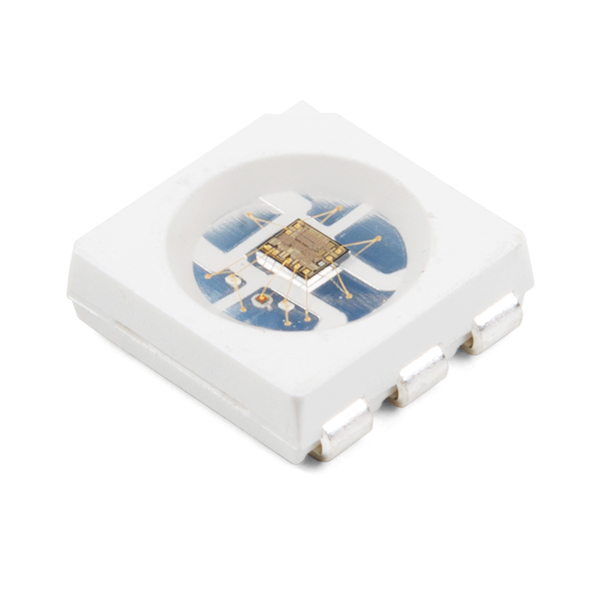
The APA102-based LED is much more than meets the eye. It may look like a common 5050-sized (5x5mm) LED, but there's actually an integrated circuit embedded inside there too. If you look really hard, you can see the tiny black chip hidden in there, along with minuscule gold wires connecting the chip to the LED. Below is a close up of an APA102.
Data Transmission Interface
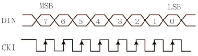
The communication interface between a microcontroller and the APA102 is not as strict WS2812's timing since it uses a 2-wire communication protocol, which consists of a clock and data line. Basically a simplified SPI interface without a slave pin.
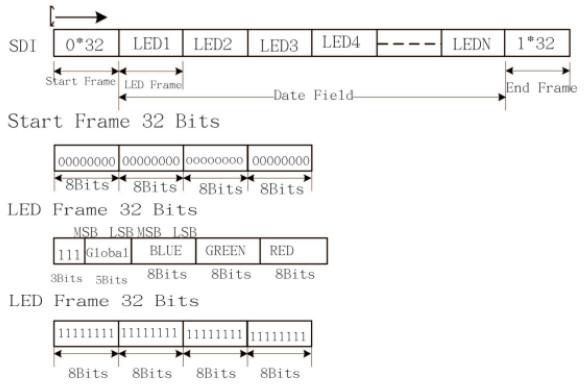
The data frame consists of a start frame, data field for the LEDs, and an end frame. The data field consists of a frame for each LED attached to the strand. Each LED frame starts with three 1's , 5 bits for brightness, 8 bits for blue, 8 bits for green, and 8 bits for red. The larger the value of a specific color is, the brighter it will be. If every color is set to 0, the LED will be off. If every color is set to max -- 255 -- the LED will be as bright and white as can be.
With the added clock line, you can use it with both a real-time processor (i.e. an Arduino) and microprocessor (i.e. Raspberry Pi). You will just need to ensure that you are using a logic level converter for 3.3V systems and make sure there is APA102 support for your architecture.