Artemis Global Tracker Hookup Guide
 QCPete,
  El Duderino
Hardware Overview
Let's take a look at the Artemis Global Tracker and all the hardware on it. There is a lot to cover here so buckle up.
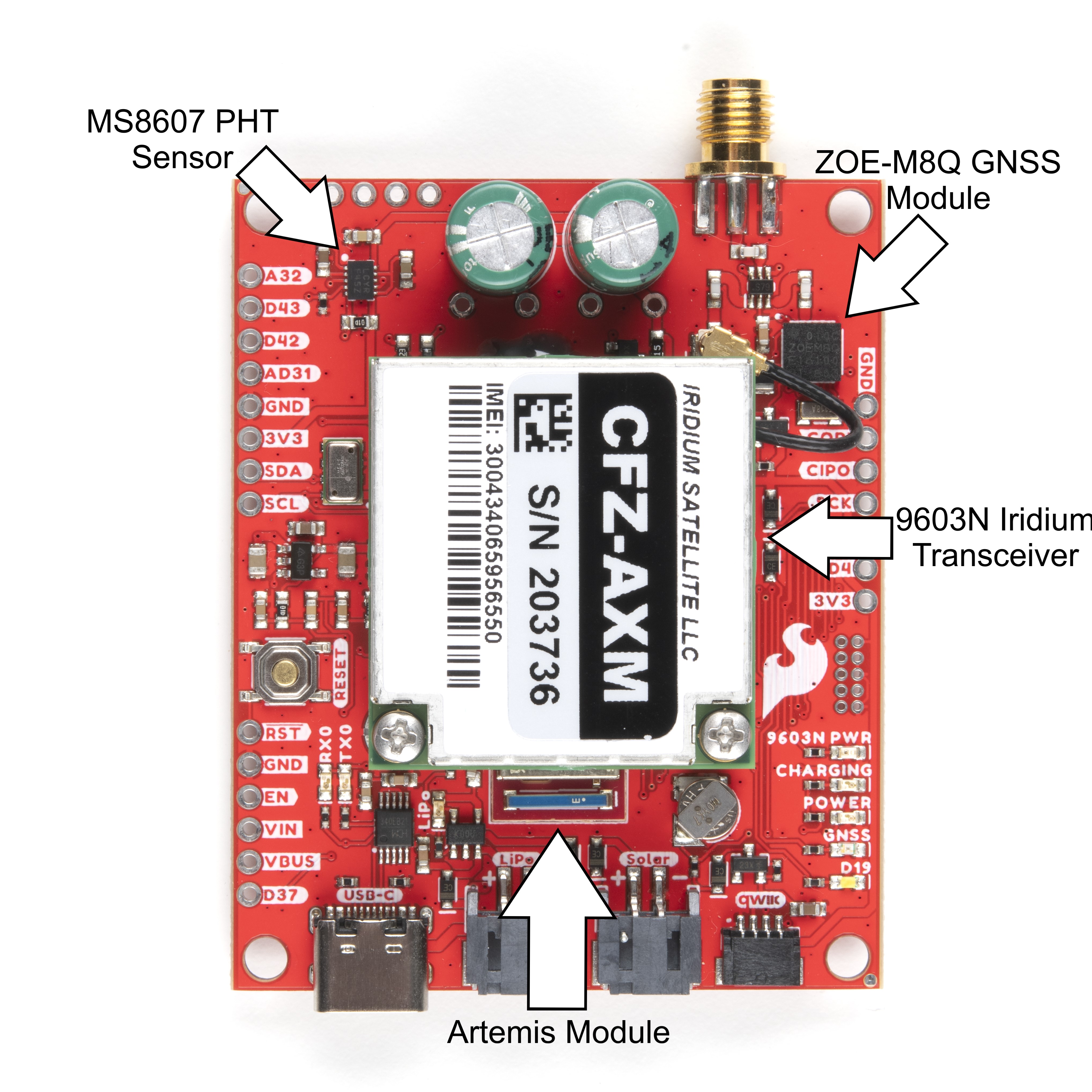
Major AGT Components
The Artemis Global Tracker combines the SparkFun Artemis module, Iridium 9603N Satellite Transceiver, ZOE-M8Q GNSS module and MS8607 PHT sensor to provide location and environmental data to a powerful, low-power processor system capable of transmitting collected data from anywhere on the planet using the Iridium Satellite network. First up we'll cover these major components in more detail.
Artemis Microprocessor
As the name suggests, the SparkFun Artemis Module rests at the core of the Artemis Global Tracker. The Artemis Module is built on the Apollo3 MCU platform and is a Cortex-M4F based module with BLE 5.0 that runs at 48MHz clock frequency (up to 96MHz burst mode) and low-power consumption as low as 6µA per MHz. The Artemis also features plenty of storage space with up to 1MB of Flash memory and up to 384KB RAM, BLE 5 RF sensitivity of -93dBm (typical) and TX peak output power of 4.0dBm. For a complete overview of the Artemis module, please review the Artemis Integration Guide and Graphical Datasheet.
The Artemis works on multiple development platforms; the SparkFun Apollo3 Arduino Core, Python, as well as Ambiq's Apollo3 SDK allowing users to choose which development environment works best for their application. Note, the examples for the Artemis Global Tracker are written for the Arduino IDE.
Iridium 9603N Satellite Transceiver
The AGT uses an Iridium 9603N Satellite Transceiver to take advantage of the Iridium Satellite transmission network to send and receive small data packets in truly remote areas with no WiFi and GSM network coverage. With a clear view of the sky, the Iridium can send short messages anywhere in the world, including polar regions outside the range of traditional wireless networks like WiFi and GSM networks. Refer to the datasheet for more information on the 9603N.
The 9603N is a small form-factor satellite transceiver that uses Iridium's satellite network in Low-Earth Orbit which reduces latency greatly as compared to networks using geostationary satellites. The 9603N design focuses on creating a robust transceiver capable of working in inhospitable environments with an operating temperature range of -40°C to 85°C and up to 75% humidity.
The module draws relatively low current during idle, transmission and receive. Short-Burst-Data transfers require the most current for short periods (8ms) but the design accommodates for that by powering the 9603N with a pair of 1F supercapacitors and charge/current regulation circuit covered in more detail below. The table below shows the typical and max values for each of those operations (all values operating at 5V):
| Operation | Current Draw |
|---|---|
| Idle | 34mA avg. (156mA peak) |
| Transmit | 145mA avg. (1.3A peak) |
| Receive | 39mA avg. (156mA peak) |
| Short-Burst Data Transfer | 158mA avg. |
The AGT ties the 9603N's Shutdown Pin to Artemis pin D17 to allow software control of power to the module. This software control is important to take note of when transmitting data using an antenna attached to the SMA connector as the 9603N shares an antenna connection with the ZOE-M8Q. The AGT includes a switching circuit to select which module uses the antenna as both modules cannot use the antenna at the same time. This circuit defaults to use the ZOE-M8Q antenna line when the device is powered so make sure to power the GNSS module down prior to transmitting data with the 9603N.
ZOE-M8Q GNSS Module
The ZOE-M8Q GNSS module from u-blox adds positional data to the Artemis Global Tracker. The ZOE-M8Q is an ultra-small GNSS module that works with all major GNSS constellations (GPS, GLONASS, Galileo and BeiDou). For a complete overview of the ZOE-M8Q refer to the datasheet. The module also supports up to four circular geofencing areas so you can trigger alarm messages sent over the Iridium network when your device either enters or exits one of those areas.
The AGT uses the ZOE-M8Q's I2C bus to communicate between the module and the Artemis controller. With a passive antenna, the ZOE-M8Q achieves up to 2.5m accuracy with GPS lock. From a cold start, the module has a Time-To-First-Fix of 29s with GPS and a hot start fix time of 1s on all constellations. The table below outlines the ZOE-M8Q's specifications:
| Parameter | Specification | GNSS Constellation | |||||
|---|---|---|---|---|---|---|---|
| GPS and GLONASS | GPS | GLONASS | BeiDou | Galileo | |||
| Horizontal Position Accuracy | --- | 2.5m | 2.5m | 4m | 3m | --- | |
| Max Navigation Update Rate | ROM | 10Hz | 18Hz | 18Hz | 18Hz | 18Hz | |
| Flash | 5Hz | 10Hz | 10Hz | 10Hz | 10Hz | ||
| Time-To-First-Fix | Cold Start | 26s | 29s | 30s | 34s | 45s | |
| Hot Start | 1s | 1s | 1s | 1s | 1s | ||
| Sensitivity | Tracking and Navigation | -167dBm | -166dBm | -166dBm | -160dBm | -159dBm | |
| Reacquisition | -160dBm | -160dBm | -156dBm | -157dBm | -153dBm | ||
| Cold Start | -148dBm | -148dBm | -145dBm | -143dBm | -138dBm | ||
| Hot Start | -157dBm | -157dBm | -156dBm | -155dBm | -151dBm | ||
| Velocity Accuracy | 0.05m/s | ||||||
| Heading Accuracy | 0.3 degrees | ||||||
Power to the ZOE-M8Q is controlled by a P-Channel MOSFET tied to Artemis pin D26. This allows users to turn the module off and on when positioning data is not needed. The board also includes a 1mAh backup battery and charging circuit for the ZOE-M8Q to allow the module to operate in Hardware Backup Mode for up to 12 hours to keep the clock running and allow a hot or warm start later. The backup battery recharges only with USB power connected (to help minimise the 3.3V current draw during sleep).
As a reminder, the ZOE-M8Q shares the antenna connection with the 9603N module. Both modules cannot use the antenna at the same time so the board includes a switching circuit to select which module uses the antenna.
MS8607 PHT Sensor
The Artemis Global Tracker includes the MS8607 Pressure, Humidity and Temperature sensor from TE Connectivity for an integrated environmental monitoring system at your remote station as well an effective altimeter for balloon applications. For a complete overview of the MS8607, refer to the datasheet.
The MS8607 offers a wide operating range with excellent precision for pressure, temperature and humidity. The table below outlines theses parameters.
| Characteristic | Pressure (mbar) | Relative Humidity (%RH) | Temperature (°C) | ||||||
|---|---|---|---|---|---|---|---|---|---|
| Min | Typ | Max | Min | Typ | Max | Min | Typ | Max | |
| Max. Operating Range | 10 | 2000 | 0 | 100 | -40 | +85 | |||
| Absolute Accuracy @25°C | 300...1100mbar | 20...80%RH | @25°C | ||||||
| -2 | 2 | -3 | 3 | -1 | 1 | ||||
| Resolution (Highest Mode) | 0.016 | 0.04 | 0.01 | ||||||
Power
The Artemis Global Tracker includes three power input options in USB-C, single-cell LiPo battery or a solar panel (or battery pack), LiPo charging circuit and a dedicated supercapacitor power and charging circuit for the 9603N.
Primary Power Inputs
Low-forward-voltage diodes isolate the three power inputs from each other so that users can have all three power sources present without harming anything on the AGT. If USB voltage is present (along with other power supplies), the AGT prefers to draw power from USB. If just Solar Cell/Battery Pack and LiPo are connected, the AGT defaults to drawing power from the Solar Cell/Battery Pack input, making the LiPo redundant.
| Power Input | Voltage Range | Notes |
|---|---|---|
| USB-C | 5V | AGT selects USB as power if voltage is present along with other power sources (LiPo/Solar/etc.) |
| LiPo Battery | 4.2-3.0V | Charging circuit only powered with voltage present on USB. |
| Solar Panel | Max 6.0V | Additional 10F capacitors recommended for 9603N module power during transmit cycles. |
| Battery Pack | 3.0-6.0V | 3x Energizer™ Ultimate Lithium AA or AAA cells are recommended for extreme environments as they operate down to -40°C. |
LiPo Battery Charge Circuit
The AGT includes a charging circuit for an attached single-cell LiPo battery using one of our favorite LiPo management controllers, the MCP73831 from Microchip. The charge circuit configuration sets the charge rate to 500mA. The LiPo charging circuit only receives power via VUSB; USB power is required to charge an attached LiPo battery.
Supercapacitors and Charge Circuit
The AGT provides power to the 9603N through a pair of supercapacitors charged by an LTC3225 supercapacitor charger regulated by an ADM4210 in-rush current limit circuit. The charge circuit defaults to source enough current (150mA) to power the 9603N during normal operation and the supercapacitors provide the extra 1.3A required during the Short Burst Data (SBD) transfers (8.3ms).
The charge circuit is configurable to switch to a lower max current (60mA) for low-current power configurations like solar. While in the low max current configuration users need to add a pair of 10F capacitors to provide the extra current required by the 9603N module during normal operation and SBD transfers.
The AGT ties the LTC3225's Shutdown Input pin to Artemis pin D27 which allows users to put the charger into Shutdown Mode to help reduce power consumption when the supercapacitor charge circuit is not needed. Set D27 LOW to put the LTC3225 into Shutdown Mode and reduce current consumption by the charge circuit to approximately 1µA. Users looking for more detailed information on the LTC3225 should refer to the datasheet.
Bus Voltage
The AGT includes a voltage monitoring circuit to keep track of the bus voltage (from the USB, LiPo or external cells). The board uses Artemis pin AD13 for voltage measurement via a simple two resistor divider dividing the bus voltage by three. Power to the resistor divider is switched by an N-channel MOSFET so the power draw can be minimized during sleep.
GPIO PTHs
The AGT breaks out an assortment of helpful GPIO pins from the Artemis module to PTH headers to interface with external devices. The board routes the following: SPI, I2C, Reset, and eleven multi-purpose GPIO pins to PTH headers:
SPI/I2C Bus and Reset PTHs
- SDA
- SCL
- RST
- CIPO
- COPI
GPIO PTHs
- AD11~
- AD12~
- AD29~
- AD31~
- AD32~
- AD35~ (SPI CS1)
- D4~ (SPI CS2)
- D15
- D37*
- D42~
- D43~
- Pins marked with a "~" are PWM-capable.
- I2C pins (SDA and SCL) are shared with ZOE-M8Q and MS8607 @3.3V.
- *D37 is a low-Impedance pin. Useful for controlling MOSFETs to power external devices.
For detailed information on alternate functionality and GPIO multiplexing options, refer to the Designing with the SparkFun Artemis tutorial and Artemis/Apollo3 Pin Function Map.
LEDs
The AGT has seven status LEDs highlighted in the photo below:
- 9603N PWR: Illuminates when the 9603N is powered on.
- CHARGING: Illuminates when the supercapacitor charge circuit is active.
- POWER: Illuminates when 3.3V is present.
- GNSS: Illuminates when ZOE-M8Q is powered on.
- D19: General status LED tied to Artemis D19.
- RX0: UART0 RX data indicator LED.
- TX0: UART0 TX data indicator LED.
Solder Jumpers
The Artemis Global Tracker has four solder jumpers labeled PWR LED, Supercaps Charge Current, 3.3V EN and MEAS.
The PWR_LED jumper allows users to disable the Power LED to help reduce power consumption for low-power applications. This jumper is CLOSED by default. Sever the trace between the two pads to open the jumper and disable the Power LED.
The Supercaps Charge Current Jumper adjusts the maximum current for the LTC3225 Supercapacitor charger by tying the PROG pin to Ground through one of two different valued resistors (12kΩ (default) and 30.1kΩ). By default, it sets the charge current to 150mA, opening the jumper sets the charge current to 60mA. When in this configuration additional capacitors are required to provide the extra power drawn by the 9603N during transmission cycles.
The 3.3V EN Jumper controls the Enable Pin on the 3.3V regulator to VIN. The jumper is CLOSED by default and ties the Enable Pin to VIN. Opening the jumper leaves the Enable Pin tied only to the PTH labeled EN on the AGT allowing users to use that PTH pin to turn the regulator on and off.
The MEAS Jumper allows users to measure the current draw of the AGT. By default, the jumper is CLOSED and nets all three power inputs to VIN.
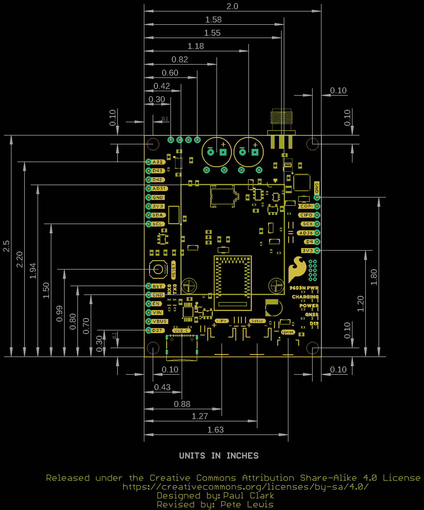
Board Dimensions
The Artemis Global Tracker measures 2.5in x 2.0in (63.5mm x 50.8mm) with four mounting holes that fit a 4-40 screw.