Assembly Guide for RedBot with Shadow Chassis
 HelloTechie
 SFUptownMaker
 Shawn Hymel
1. Wheel Encoders (SIK)
Read on if you have the SIK for RedBot or are using the Wheel Encoder Kit. If not, skip to the next section.
The Wheel Encoder Kit is a simple add-on sensor that can be used to detect how far each wheel rotates. The wheel encoders will allow you to monitor and control the distance the robot travels. The Wheel Encoder Kit uses a multi-pole diametric ring magnet attached to the motor shaft. As the motor spins, the ring magnet spins as well. This is detected by a small magnetic sensor called a hall effect sensor. The RedBot can use this sensor input to count / track the number of rotations of the motor and hence how far the wheel moves.
NOTE: You will likely need some scissors to open the Wheel Encoder Kit. Also, the Encoder Kit might contain some extra parts (e.g. screws and some blue mounting bars). You won't need those, as the Shadow Chassis contains all the necessary mounting hardware.
Locate the Following:
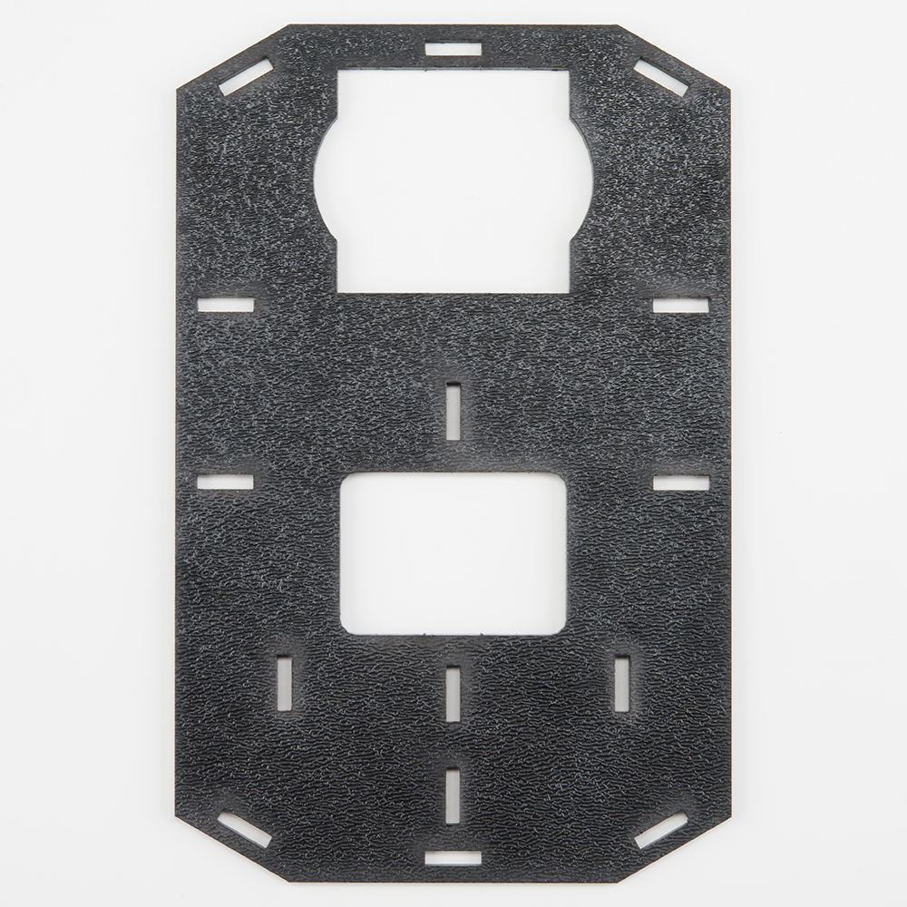
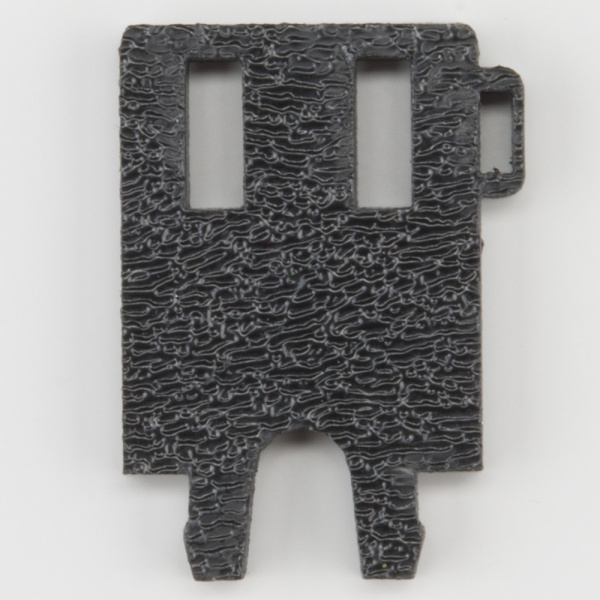
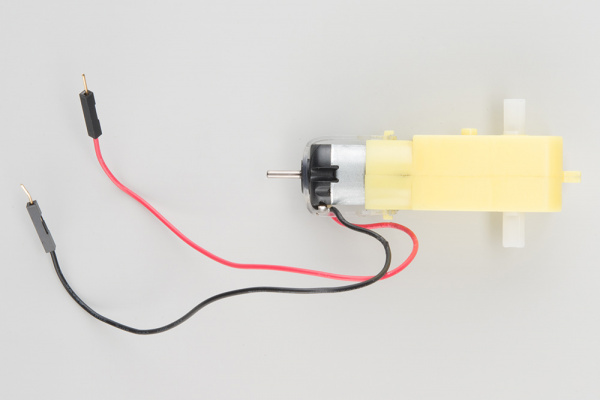
| 1x Bottom Chassis Plate (A) | 2x Encoder Mount (F) | 2x Motor (K) |
 |
 |
 |
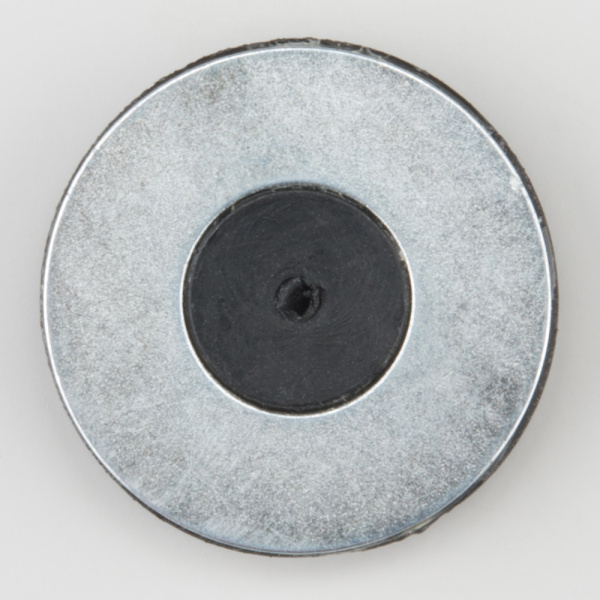
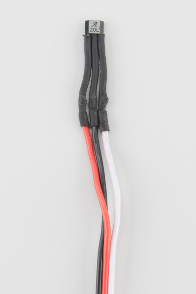
| 2x Encoder Magnet Plate (N) | 2x Encoder Hall Effect Sensor (O) | |
 |
 |
Add the Magnets
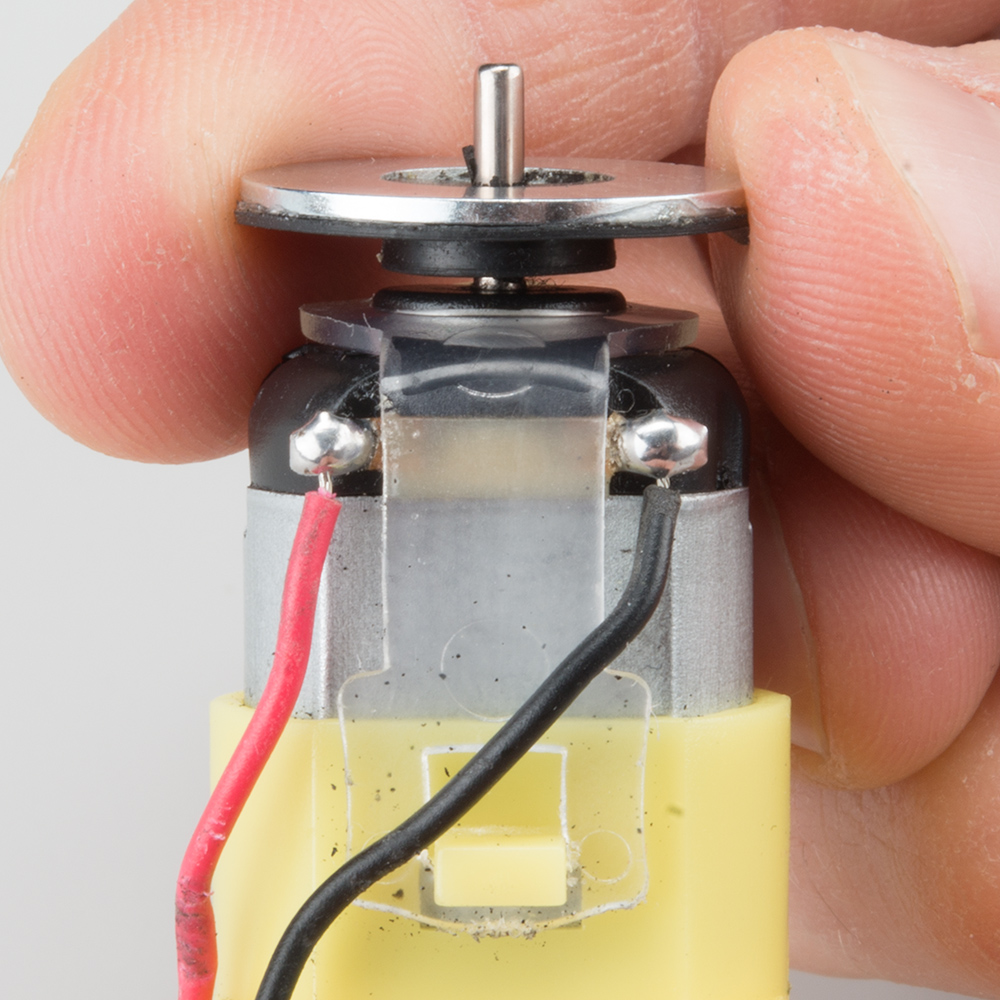
Slide the Encoder Magnet Plates (N) onto the metal shaft on the back of the Motors (K). Note that magnet side (silver) should face away from the motor. Slide the magnet down onto the shaft, but make sure that it does not rub or interfere with the back of the motor housing.
Repeat this for both motors.
Attach the Hall Effect Sensors
Left Encoder
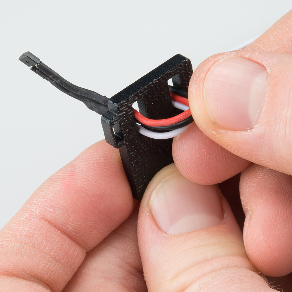
Take one of the Encoder Mounts (F) and hold it so that the protruding slot is on the left. Push one of the encoder sensors through the first slot on the right.
Note: The direction of the sensor does not matter.
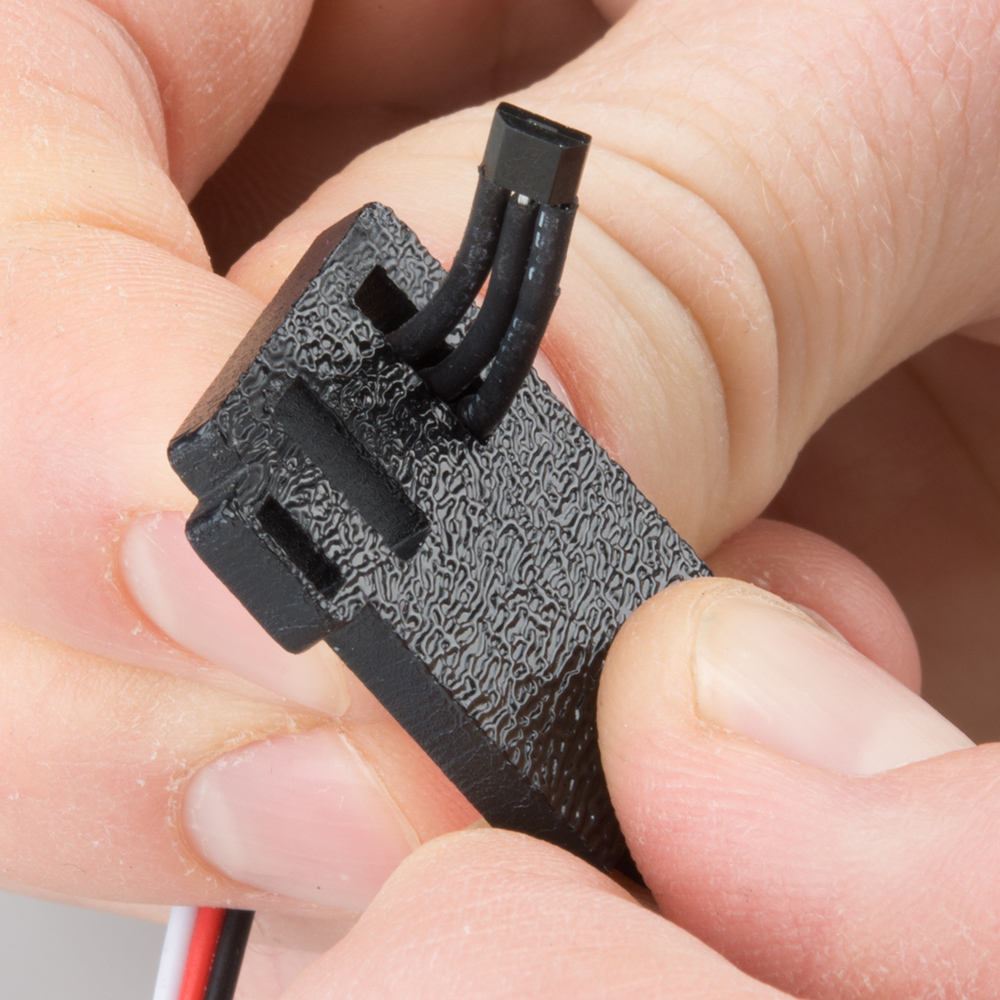
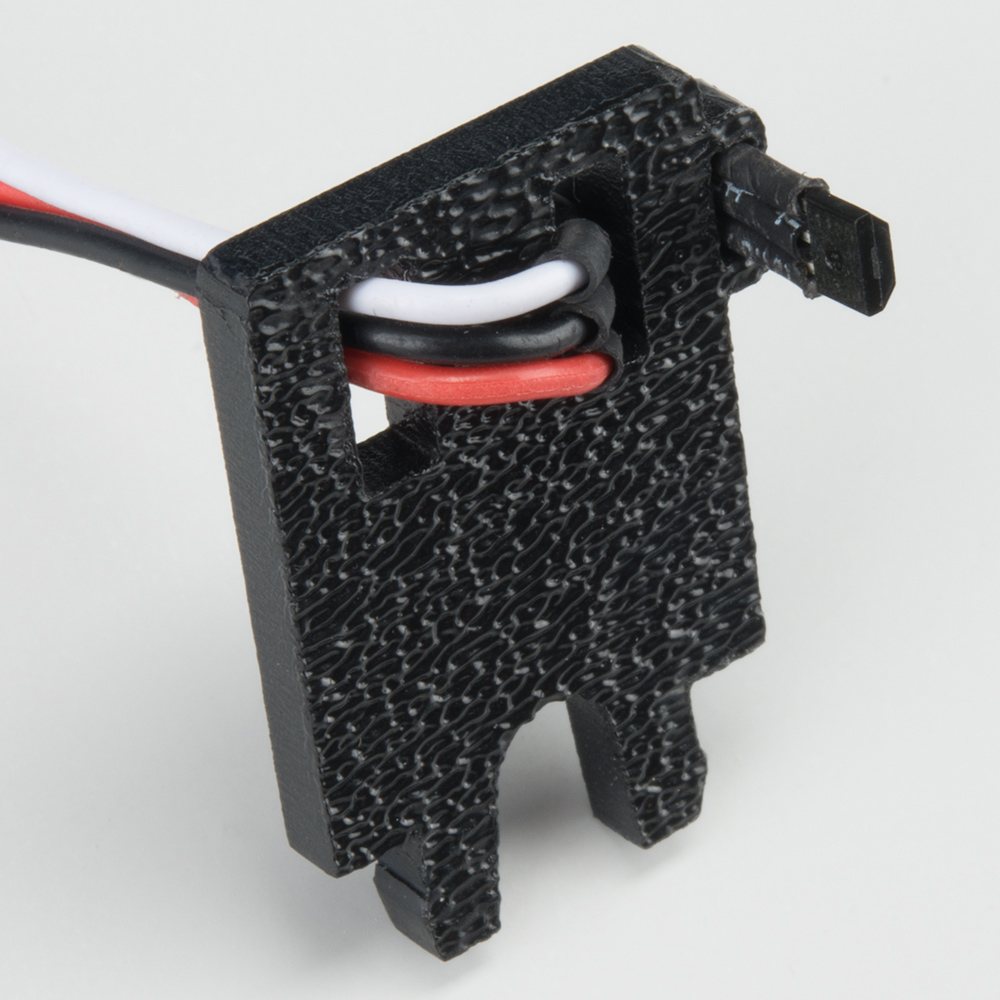
Loop the sensor and push it through the second (middle) slot.
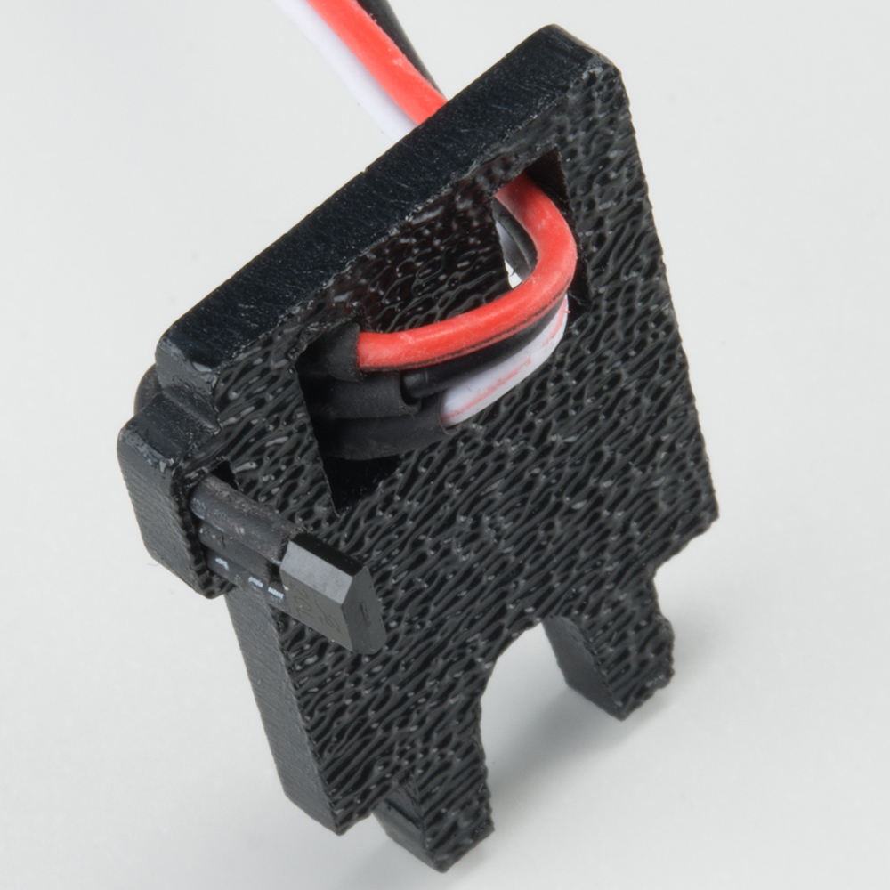
Once more, push the sensor through the small protruding slot on the left. Carefully pull the wires so there is no more slack in the mount. Make sure the whole sensor can be seen coming out of the final slot (the sensor should protrude between 1/4" and 3/8" past the mount).
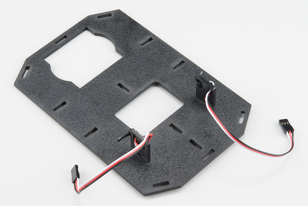
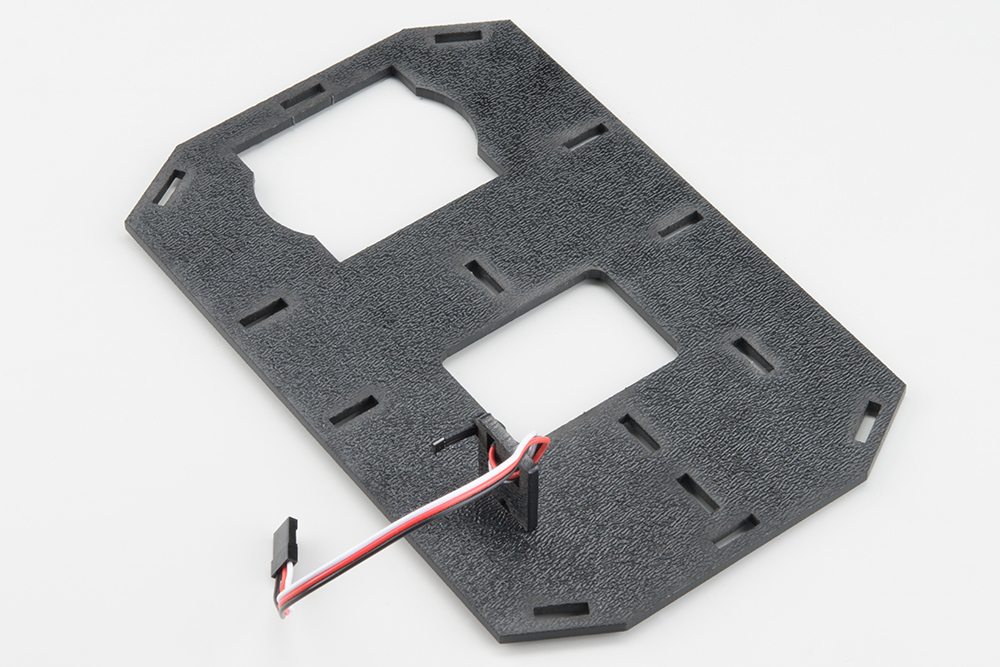
Snap the assembled encoder mount into the back-left vertical slot of the Bottom Chassis Plate (A).
Right Encoder
The right encoder is a mirrored assembly of the left encoder.
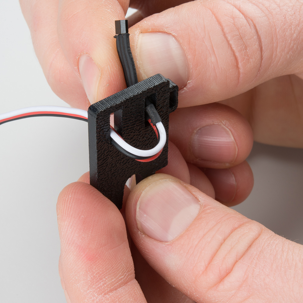
Take the other Encoder Mount (F) and hold it so that the protruding slot is on the right. Push the other encoder sensor through the first slot on the left.

Loop the sensor and push it through the second (middle) slot.
Once more, push the sensor through the protruding slot on the right. Carefully pull the wires so there is no more slack in the mount. Make sure the whole sensor can be seen coming out of the final slot (the sensor should protrude between 1/4" and 3/8" past the mount).
Snap the assembled encoder mount into the back-left vertical slot of the Bottom Chassis Plate (A). Note that the hall effect sensors are facing to the outside of the chassis.