Assembly Guide for RedBot with Shadow Chassis
 HelloTechie
 SFUptownMaker
 Shawn Hymel
Introduction
The SparkFun RedBot is a platform for teaching basic robotics and sensor integration! It is based on the SparkFun RedBoard and fully programmable using Arduino. This guide describes the assembly of the new Shadow Chassis for the RedBot. If you want to learn how to program your robot, see the Experiment Guide for RedBot.
NOTE: We recommend that you read all of the directions first, before building your RedBot.
RedBot Basic Kit vs. SIK for RedBot
This tutorial will cover how to install all the parts in the SparkFun RedBot Basic Kit and the SparkFun Inventor's Kit for RedBot (SIK for RedBot).
SparkFun RedBot Basic Kit
We have two flavors of the RedBot available - the Basic kit and the SparkFun Inventor's Kit for RedBot. If you have the SparkFun RedBot Basic Kit, you can skip the sections marked with (SIK).
Alternatively, you can pick up additional sensors to install on your RedBot. These parts include the Wheel Encoder Kit, RedBot Buzzer, and two RedBot Mechanical Bumpers. Follow the sections in this guide that covers any of the extra sensors you might have.
SIK for RedBot
The SIK for RedBot has a few extra parts that you won't see in the Basic Kit. These include the mechanical bump sensors (whiskers), the buzzer, and wheel encoders. If you have the SIK for RedBot, you can follow all the sections in this guide, including those marked with (SIK).
Materials
The SparkFun RedBot Basic Kit contains the following pieces. SIK-only parts are noted with an asterisk (*). Note that several of the parts need to be snapped out of the main chassis boards.

| Part | Qty | |
|---|---|---|
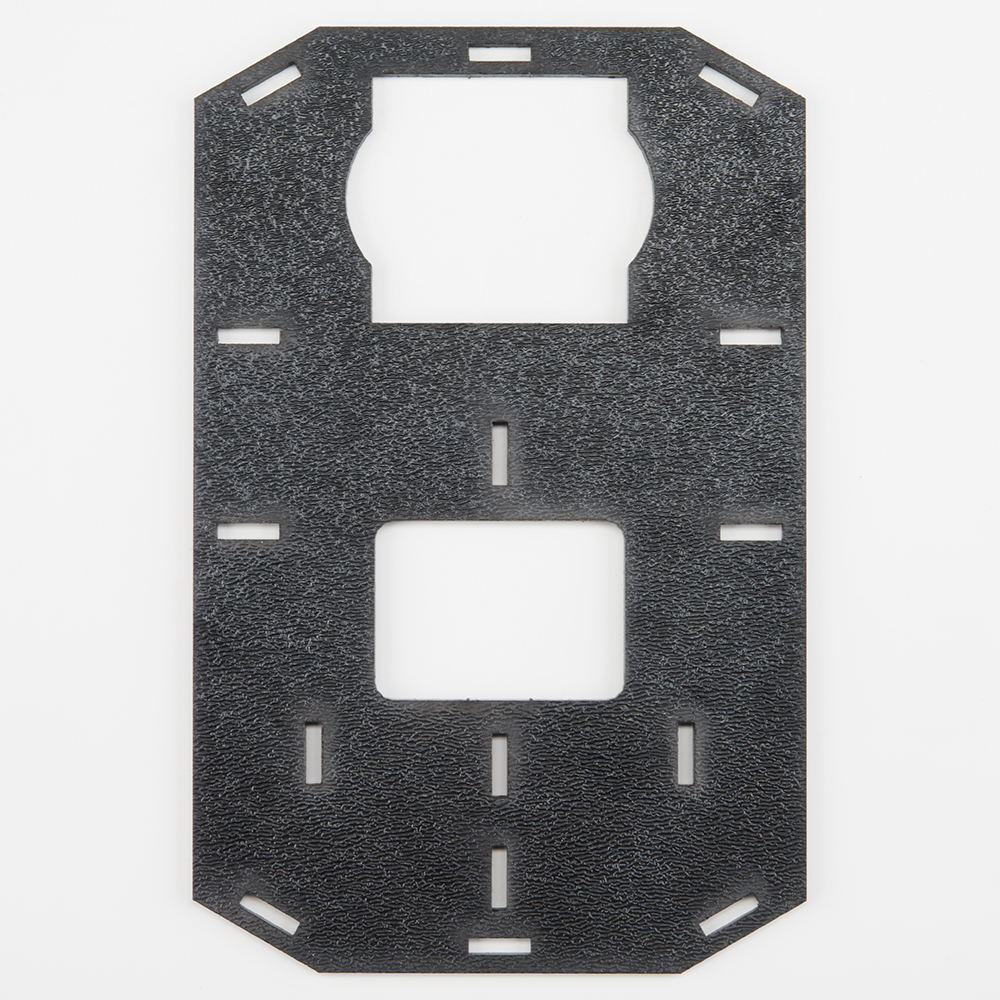
| A | Bottom Chassis Plate | 1 |
| B | Top Chassis Plate | 1 |
| C | Front Motor Mount | 2 |
| D | Rear Motor Mount | 2 |
| E | Side Strut | 4 |
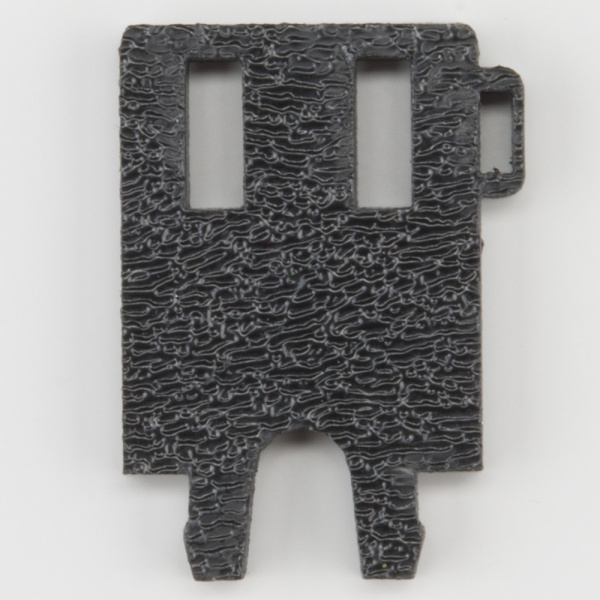
| F | Encoder Mount | 2 |
| G | Mainboard Mount | 2 |
| H | Battery Pack Clip | 1 |
| I | Line Follower Mount | 1 |
| J | Line Follower Mount Plate | 1 |
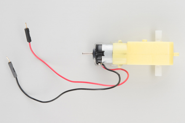
| K | Motor | 2 |
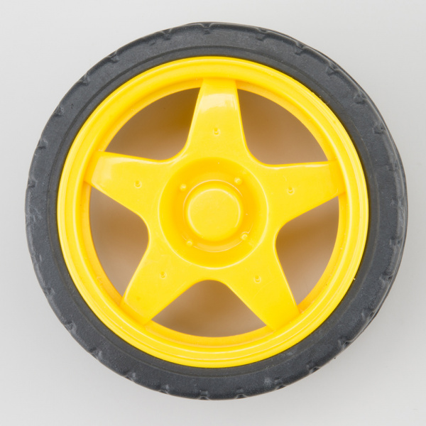
| L | Wheel | 2 |
| M | Nub Caster | 1 |
| N* | Encoder Magnet Plate (SIK) | 2 |
| O* | Encoder Hall Effect Sensor (SIK) | 2 |
| P | RedBot Mainboard | 1 |
| Q | Line Follower Board | 3 |
| R | Accelerometer Board | 1 |
| S* | Buzzer Board (SIK) | 1 |
| T* | Bumper Board (SIK) | 2 |
| U* | Bumper Whisker (SIK) | 2 |
| V* | #4-40 x 3/8" Screw (SIK) | 6 |
| W* | #4-40 Nylon Standoff (SIK) | 2 |
| X* | #4-40 Hex Nut (SIK) | 2 |
| Y | 3-Wire Jumper Cable (SIK) | 3 (5*) |
| Z | Battery Holder | 1 |
| AA* | AA Batteries (SIK) | 4 |
| AB* | Screwdriver (SIK) (Not Shown) | 1 |
| AC* | USB Mini-B Cable (SIK) (Not Shown) | 1 |
| * Indicates parts included in the SIK for RedBot | ||
IMPORTANT: If you have the RedBot Basic Kit, you will need 4x AA batteries.
Recommended Tools
None! The RedBot Basic Kit does not require any additional tools. The SIK for RedBot comes with a screwdriver, which you will need to mount the Bumper Boards. If you bought the Bumper Boards separately, you will need a Phillips screwdriver.
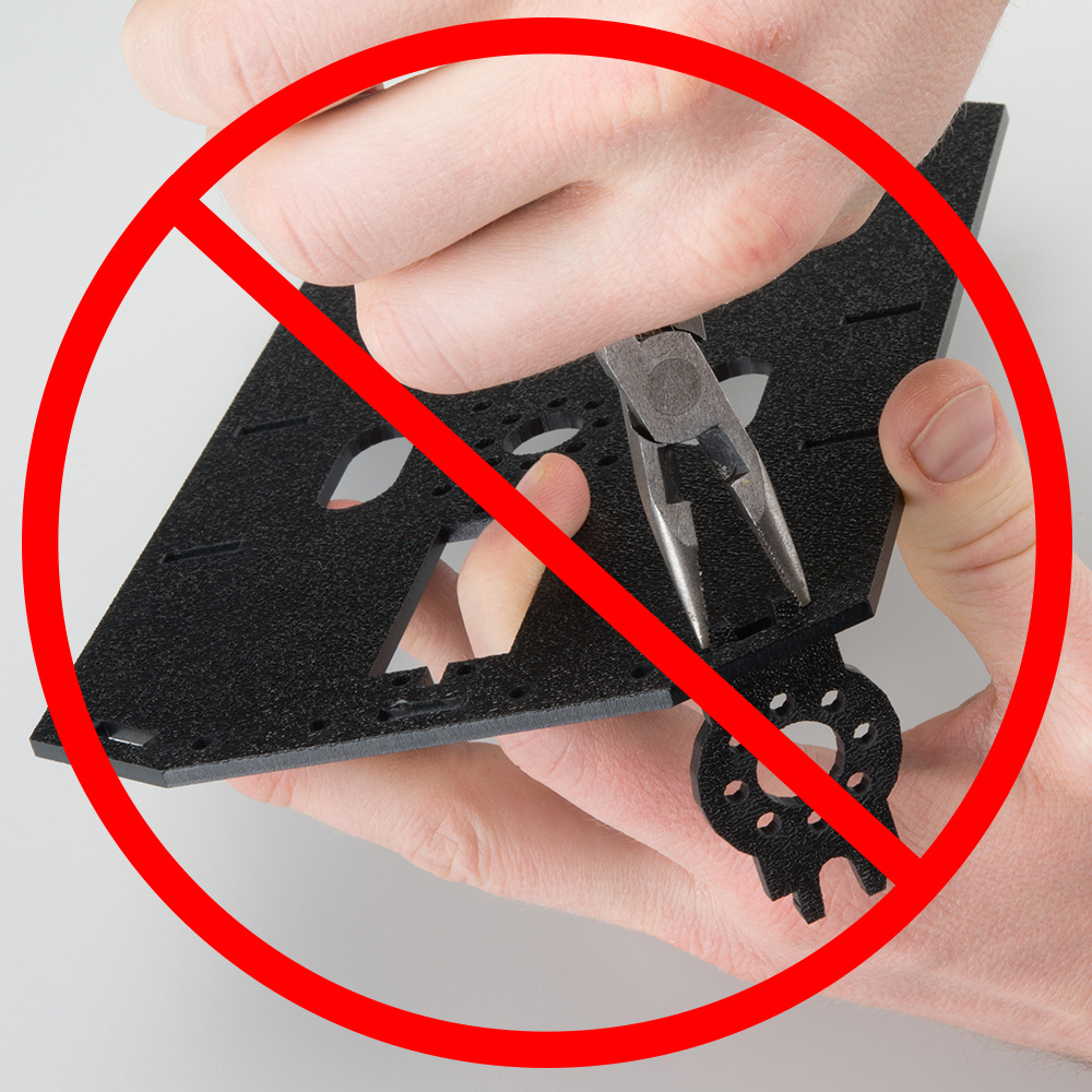
WARNING: Do not attempt to remove chassis parts by squeezing them with pliers. You will break them, and the robot will be sad.
A Note About Directions
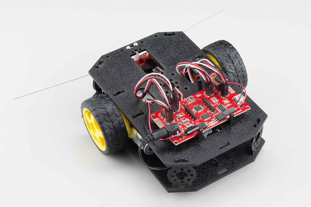
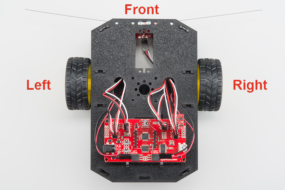
When we talk about the "front," "left," "right," and "back" of the RedBot, we are referring to specific sides of the robot when viewed from above.
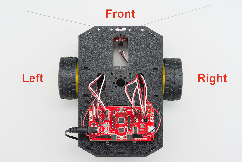
Notice that we consider the Mainboard to be on the "back" of the RedBot and the Bumper Whiskers and Line Follower Boards to be in the "front."
1. Wheel Encoders (SIK)
Read on if you have the SIK for RedBot or are using the Wheel Encoder Kit. If not, skip to the next section.
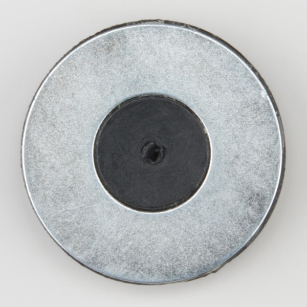
The Wheel Encoder Kit is a simple add-on sensor that can be used to detect how far each wheel rotates. The wheel encoders will allow you to monitor and control the distance the robot travels. The Wheel Encoder Kit uses a multi-pole diametric ring magnet attached to the motor shaft. As the motor spins, the ring magnet spins as well. This is detected by a small magnetic sensor called a hall effect sensor. The RedBot can use this sensor input to count / track the number of rotations of the motor and hence how far the wheel moves.
NOTE: You will likely need some scissors to open the Wheel Encoder Kit. Also, the Encoder Kit might contain some extra parts (e.g. screws and some blue mounting bars). You won't need those, as the Shadow Chassis contains all the necessary mounting hardware.
Locate the Following:
| 1x Bottom Chassis Plate (A) | 2x Encoder Mount (F) | 2x Motor (K) |
 |
 |
 |
| 2x Encoder Magnet Plate (N) | 2x Encoder Hall Effect Sensor (O) | |
 |
 |
Add the Magnets
Slide the Encoder Magnet Plates (N) onto the metal shaft on the back of the Motors (K). Note that magnet side (silver) should face away from the motor. Slide the magnet down onto the shaft, but make sure that it does not rub or interfere with the back of the motor housing.
Repeat this for both motors.
Attach the Hall Effect Sensors
Left Encoder
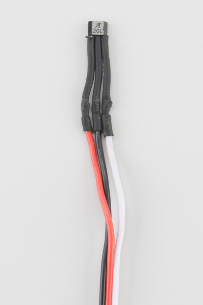
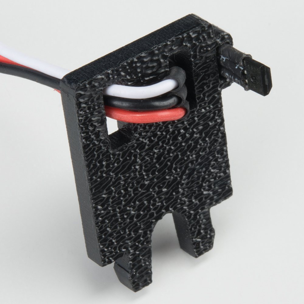
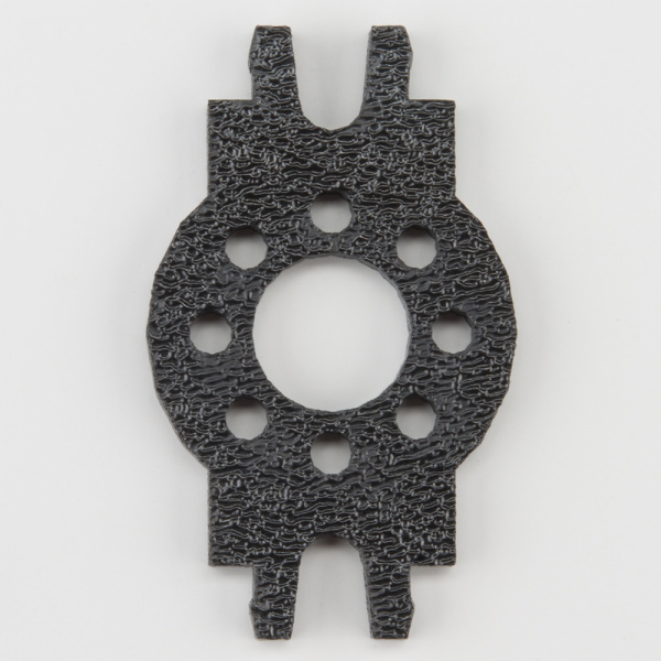
Take one of the Encoder Mounts (F) and hold it so that the protruding slot is on the left. Push one of the encoder sensors through the first slot on the right.
Note: The direction of the sensor does not matter.
Loop the sensor and push it through the second (middle) slot.
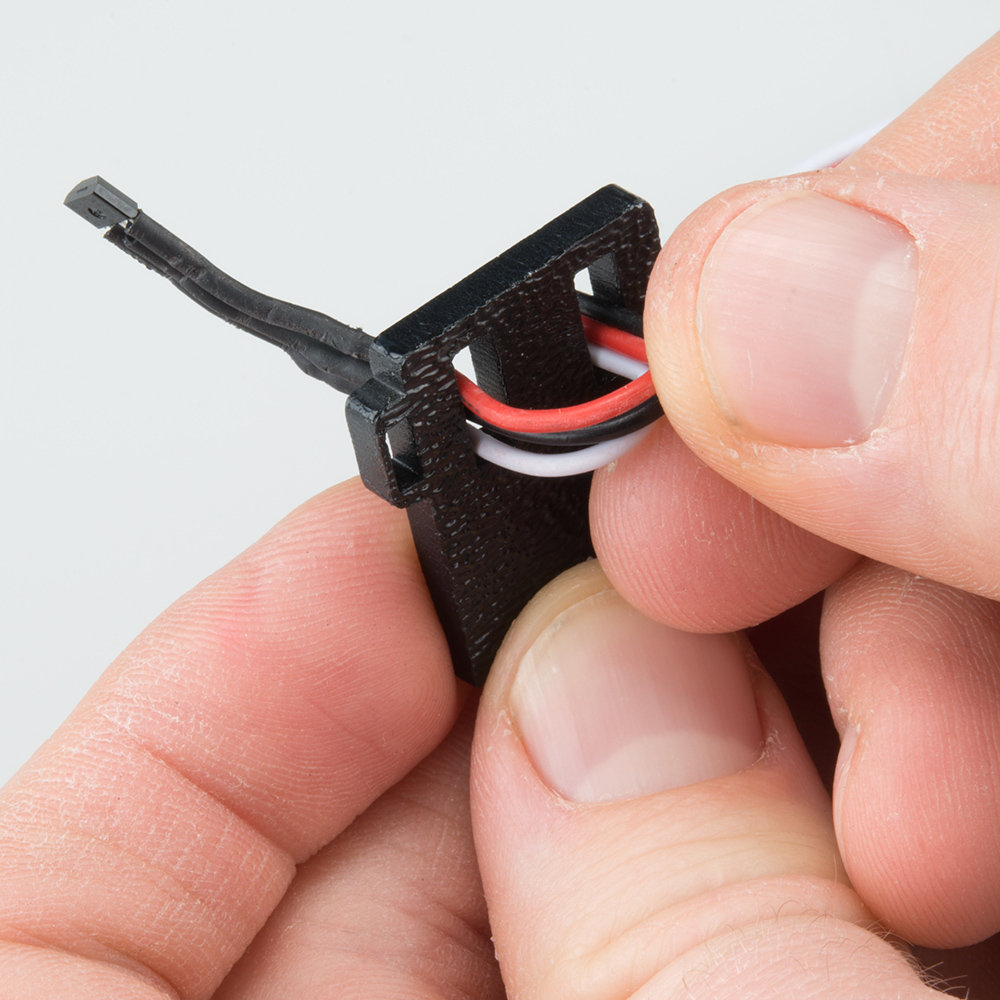
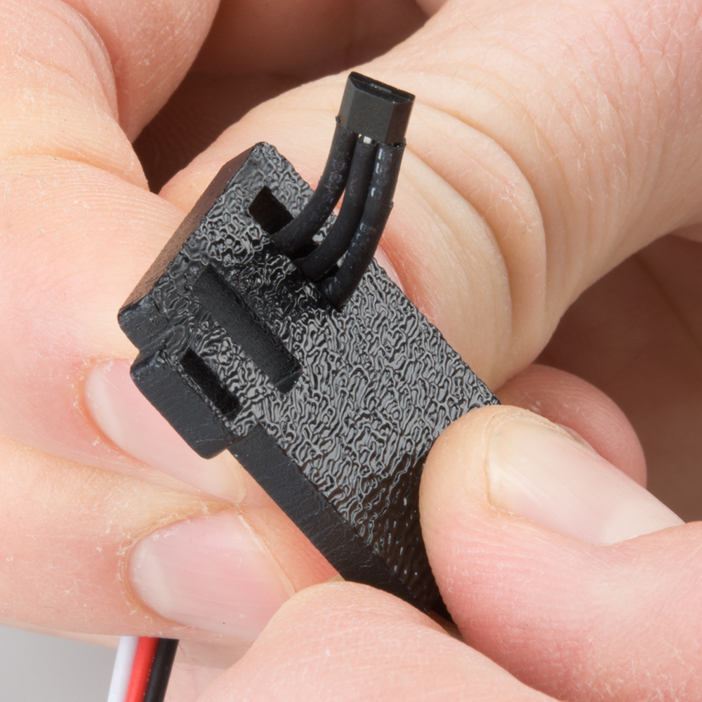
Once more, push the sensor through the small protruding slot on the left. Carefully pull the wires so there is no more slack in the mount. Make sure the whole sensor can be seen coming out of the final slot (the sensor should protrude between 1/4" and 3/8" past the mount).
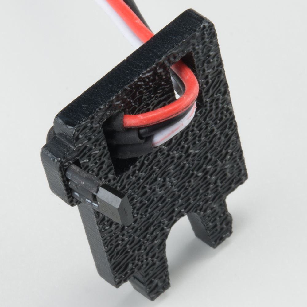
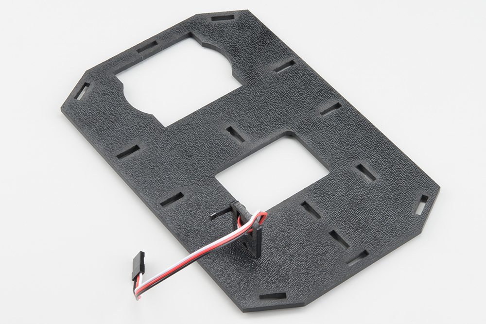
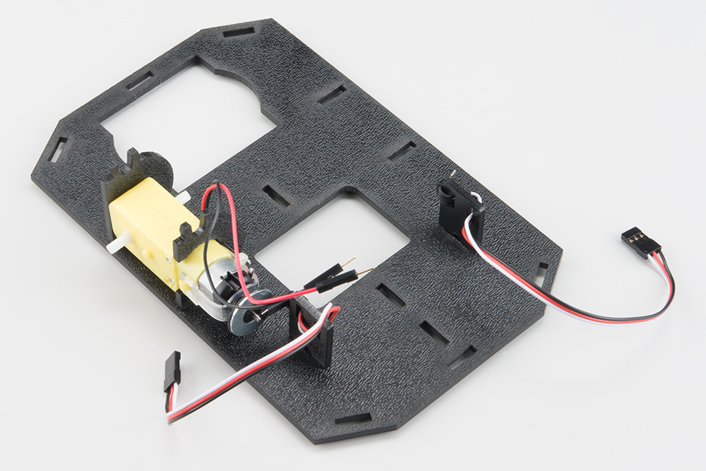
Snap the assembled encoder mount into the back-left vertical slot of the Bottom Chassis Plate (A).
Right Encoder
The right encoder is a mirrored assembly of the left encoder.
Take the other Encoder Mount (F) and hold it so that the protruding slot is on the right. Push the other encoder sensor through the first slot on the left.

Loop the sensor and push it through the second (middle) slot.
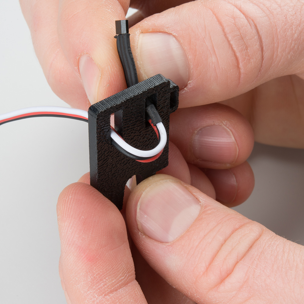
Once more, push the sensor through the protruding slot on the right. Carefully pull the wires so there is no more slack in the mount. Make sure the whole sensor can be seen coming out of the final slot (the sensor should protrude between 1/4" and 3/8" past the mount).
Snap the assembled encoder mount into the back-left vertical slot of the Bottom Chassis Plate (A). Note that the hall effect sensors are facing to the outside of the chassis.
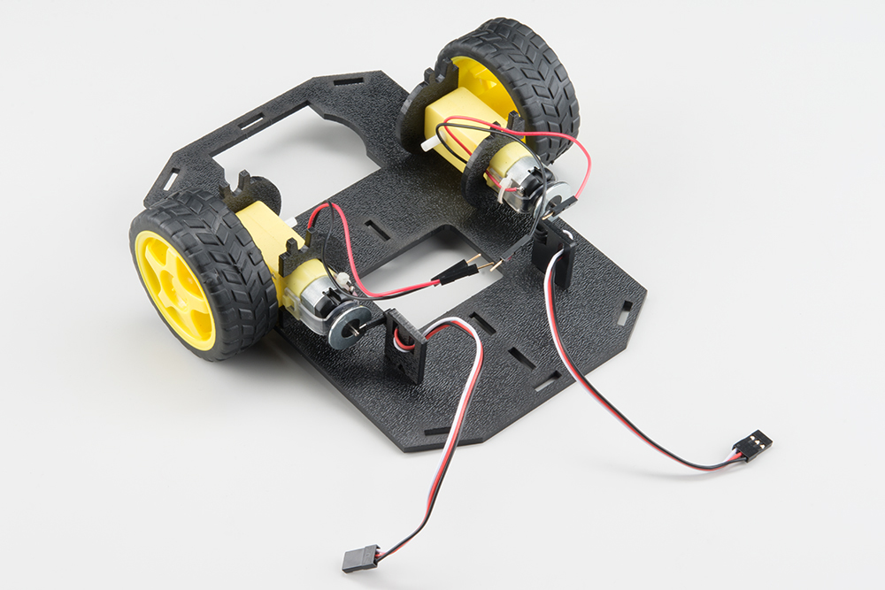
2. Motors and Wheels
The motors add some motion to the RedBot by turning the nice, rubbery wheels.
NOTE: If you completed the previous Wheel Encoder (SIK) step, your motors will each have an encoder magnet plate attached to their rear shaft. However, they are not necessary to complete this step.
ALSO NOTE: Your motors might not be yellow. Worry not, they will work just as well!
Locate the Following:
| 2x Front Motor Mount (C) | 2x Rear Motor Mount (D) | 2x Motor (K) |
 |
 |
|
| 2x Wheel (L) | ||
 |
Attach Rear Motor Mounts
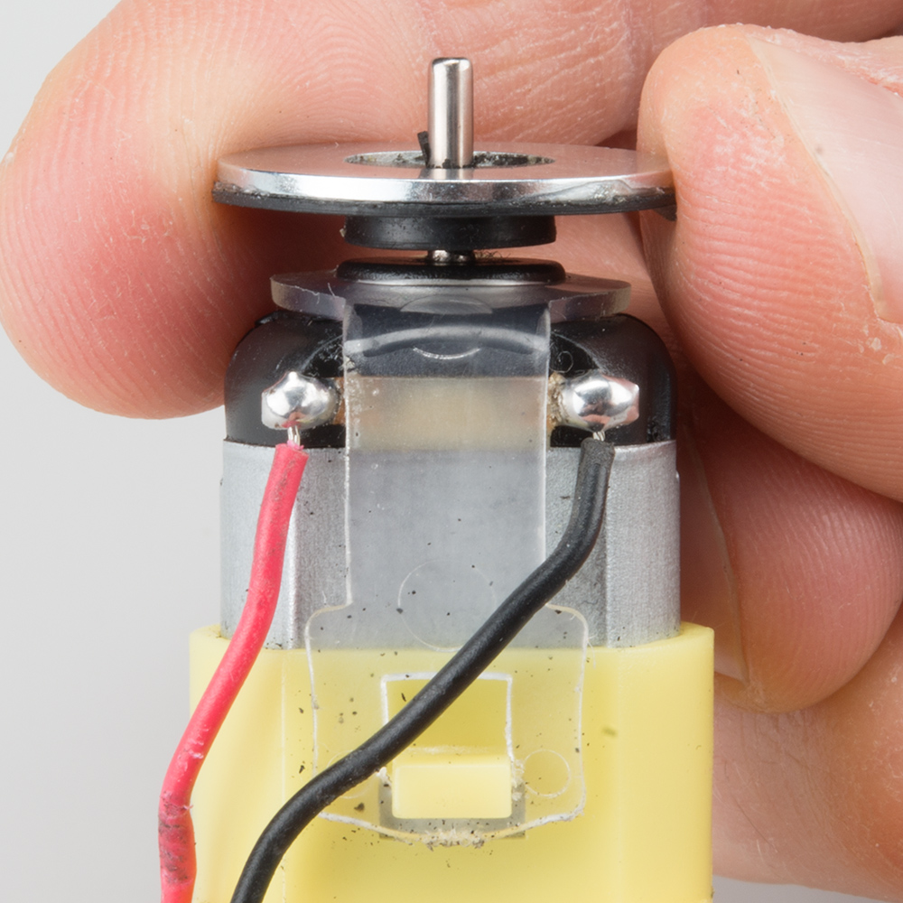
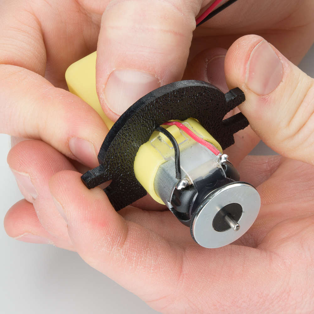
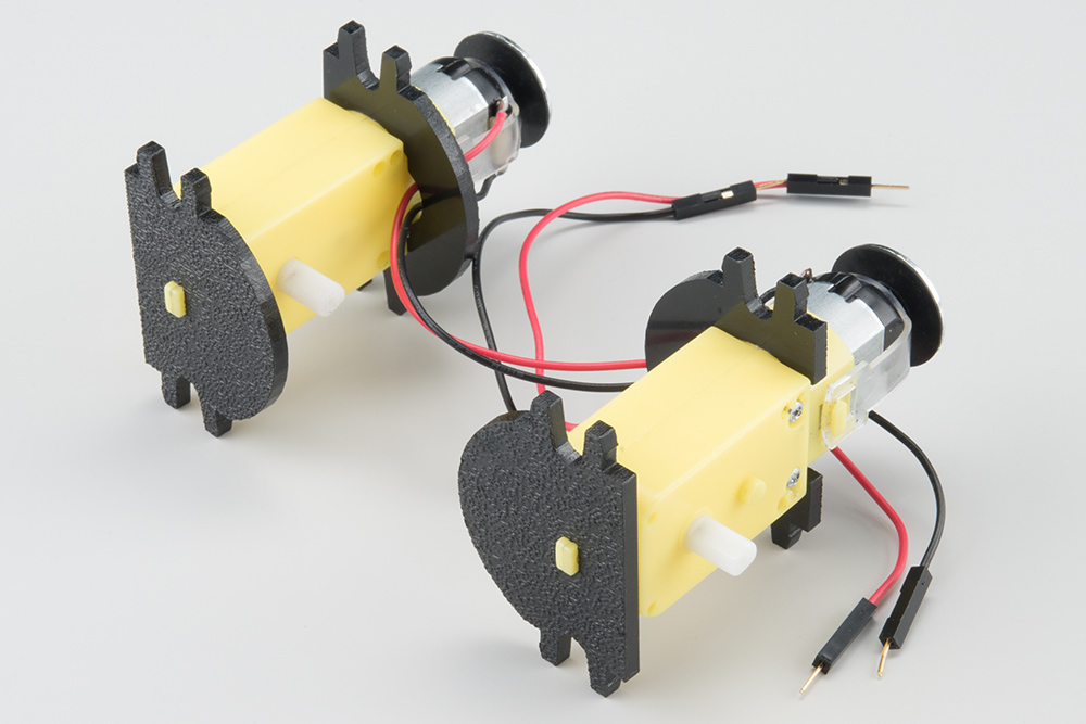
Hold the wires near the middle of the Motor (K), and carefully slide a Rear Motor Mount (D) in from the side and over the two motor wires. Be careful not to snag the wires, the cable tie, or the clear plastic strap.
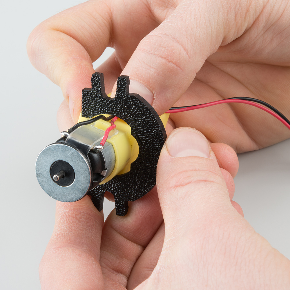
Holding the motor wires, gently twist the Rear Motor Mount counter clockwise so that it snaps in place on the motor and the wires are centered in the gap of the motor mount. Again, be sure not to snag the wires under the motor mount.
Repeat the process for the second motor.

Attach the Front Motor Mounts
Slide a Front Motor Mount (C) onto the protruding eyelet on the front of a Motor (K). Ensure the rounded sides of the motor mounts are facing the same way.
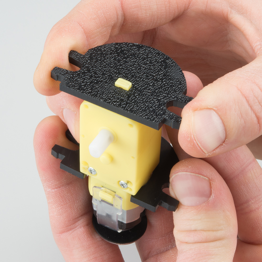
Repeat the process for the second motor.
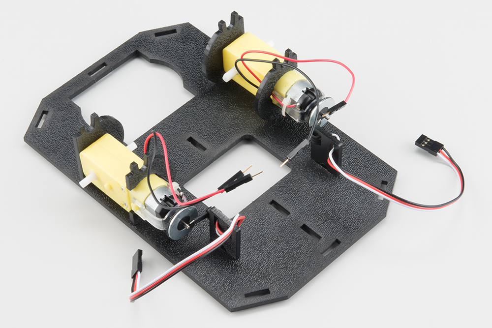
Attach the Motor Assemblies to the Chassis
Snap one of the motor assemblies into the left 2 horizontal slots of the Bottom Chassis Plate (A). Make sure that the rounded edges of the motor mounts and the wires are facing toward the center of the chassis.
Snap the other motor assembly into the right 2 horizontal slots of the Bottom Chassis Plate (A). Again, make sure that the rounded edges of the motor mounts and the wires are facing the center of the chassis.
Attach the Wheels
Slide one Wheel (L) onto the plastic shaft of a Motor (K). Look at the motor shaft. Notice it has two flat edges. Make sure to line up the flat edges of the motor shaft with the flat edges of the wheel.
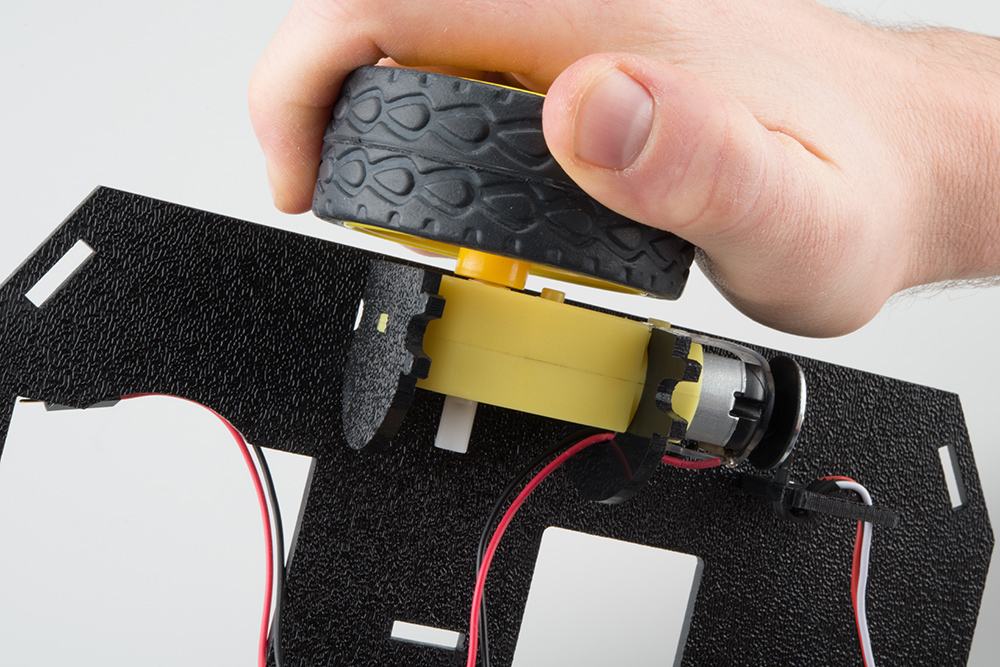
Repeat with the other wheel.
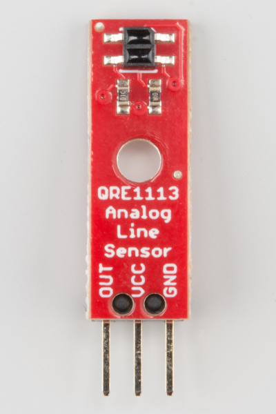
3. Line Follower
In this section, you will be putting standoffs on the RedBot Sensor - Line Followers. Then you will add the sensors to your chassis.
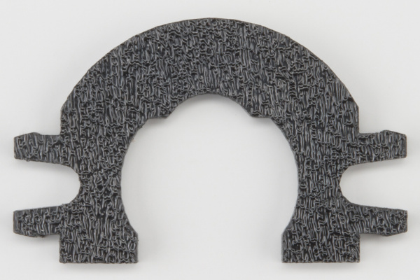
Locate the Following:
| 1x Line Follower Mount (I) | 1x Line Follower Mount Plate (J) | 3x Line Follower Board (Q) |
 |
 |
 |
| 3x 3-Wire Jumper Cable (Y) | ||
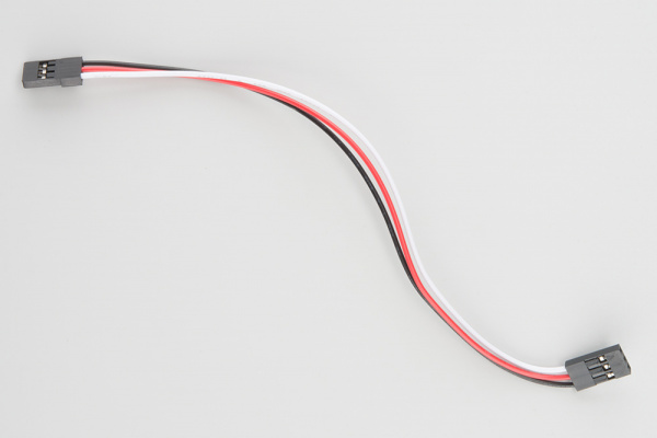 |
> |
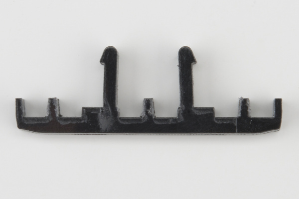
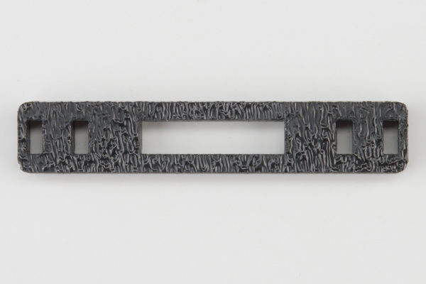
Construct the Line Follower Assembly
Attach the 3 Line Follower Boards (Q) to the Line Follower Mount (I) such that the rectangular pegs in the Line Follower Mount poke through the mounting holes in the Line Follower Boards. Make sure the sensors are facing away/down from the clip of the mount.
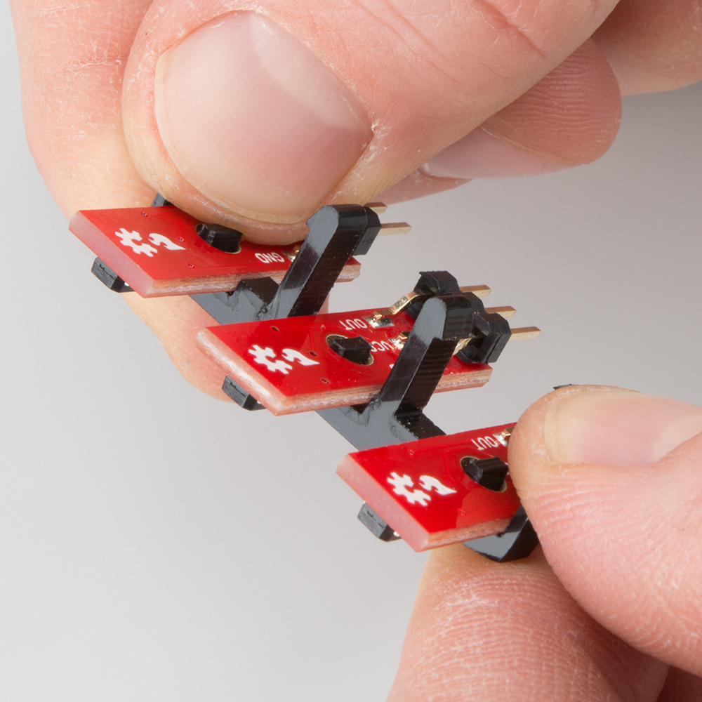
Place the Line Follower Mount Plate (J) on top of the Line Follower Mount (I) so that the center clip of the mount is poking through the center slot of the plate.

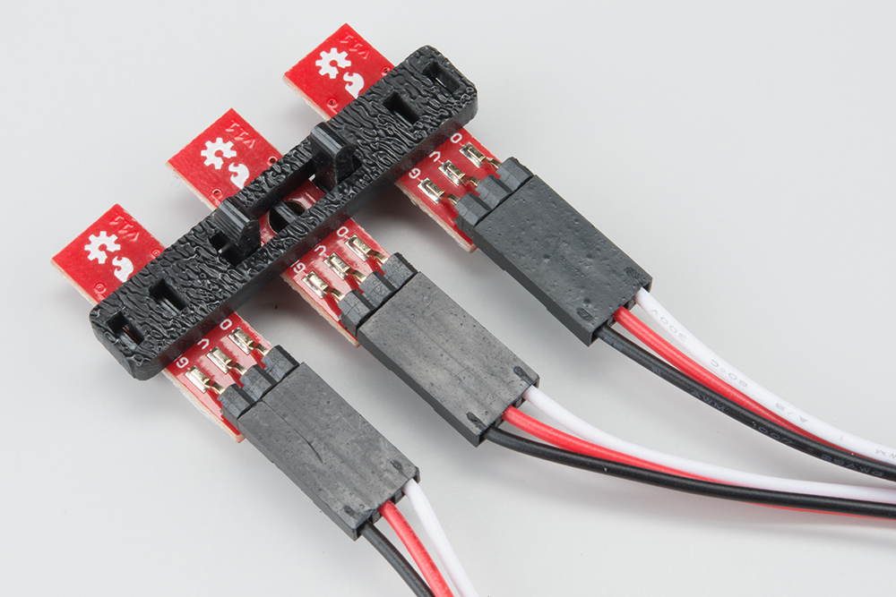
Attach the Cables
You will need to connect a 3-Wire Jumper Cable (Y) to each of the Line Follower Boards (Q). Note the color of the wire attached to each pin.
Line Follower Connections:
| Jumper Wire Color | RedBot Sensor - Line Follower |
|---|---|
| Black | GND |
| Red | VCC |
| White | OUT |
Attach all 3 cables to the 3 Line Follower Boards. Notice that the white wire should be on the right and the black wire should be on the left.
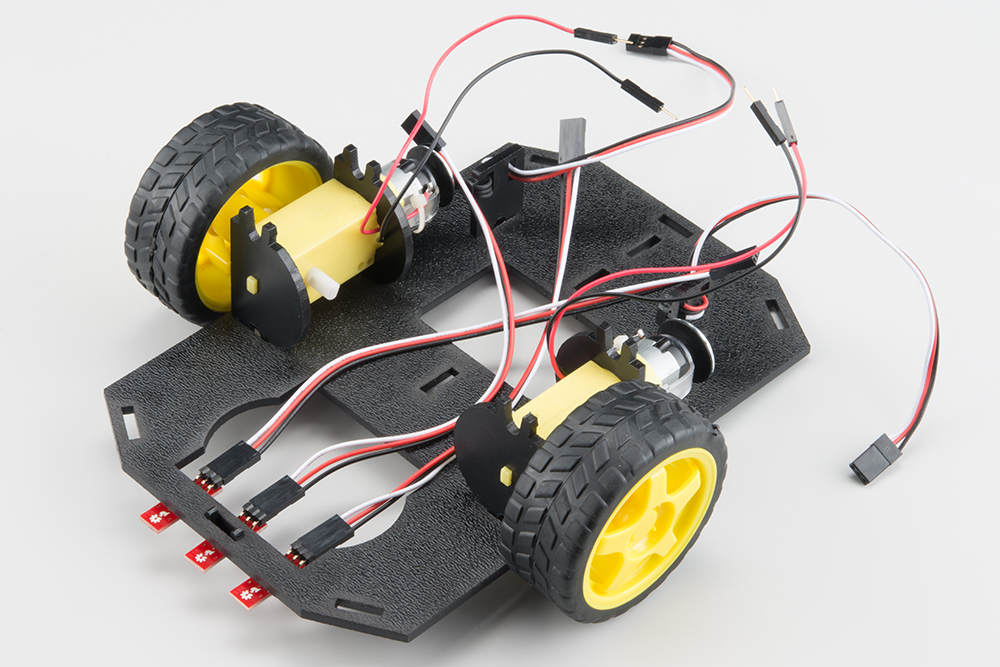
Attach the Line Follower Assembly to the Chassis
Locate the wide, rectangular slot near the front of the chassis and snap the line follower assembly in from the bottom side of the chassis. Route the cables through the large hole in the bottom plate.
4. Mechanical Bumpers (SIK)
Read on if you have the SIK for RedBot or are using the Mechanical Bumpers. If not, skip to the next section.
One of the sensors included in the SIK for RedBot are a set of Whisker Mechanical Bumpers. These are basically simple switches that close a circuit when the whisker pushes against an object. The whiskers are made from a thick music wire and a simple RedBot Bumper board. You will need to prepare the music wire by bending the wire itself. Then, you will add standoffs and screws to your mechanical bumpers, followed by adding the mechanical bumpers to the RedBot chassis.
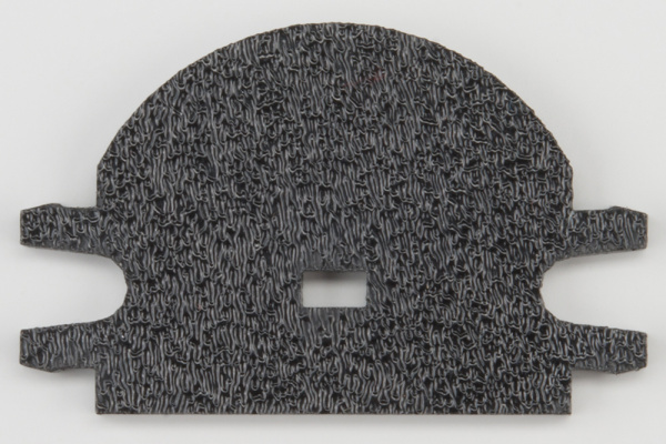
Locate the Following:
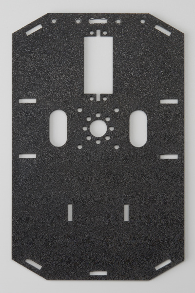
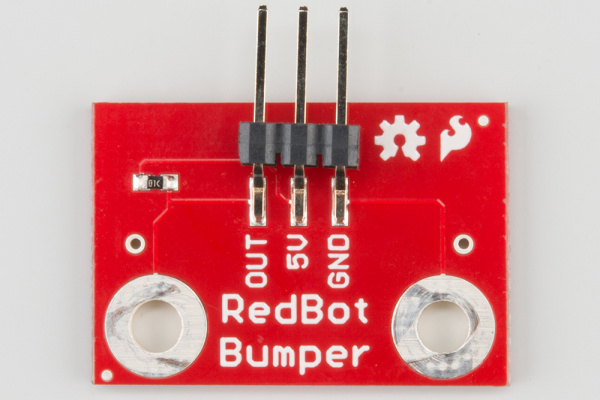
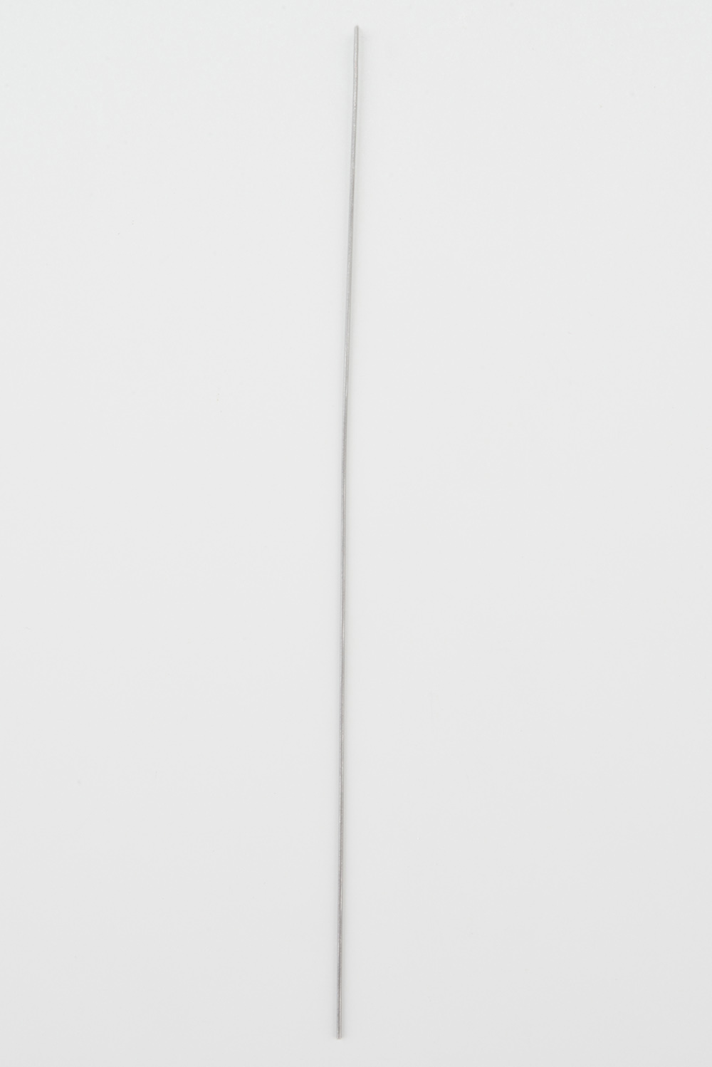
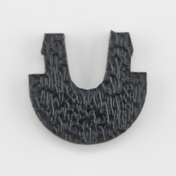
| 1x Top Chassis Plate (B) | 2x Bumper Board (T) | 2x Bumper Whisker (U) |
 |
 |
 |
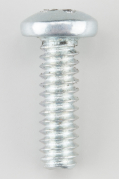
| 6x #4-40 x 3/8" Screw (V) | 2x #4-40 Nylon Standoff (W) | 2x #4-40 Hex Nut (X) |
 |
 |
 |
| 2x 3-Wire Jumper Cable (Y) | 1x Phillips Screwdriver (AB) | |
|
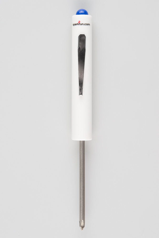 |
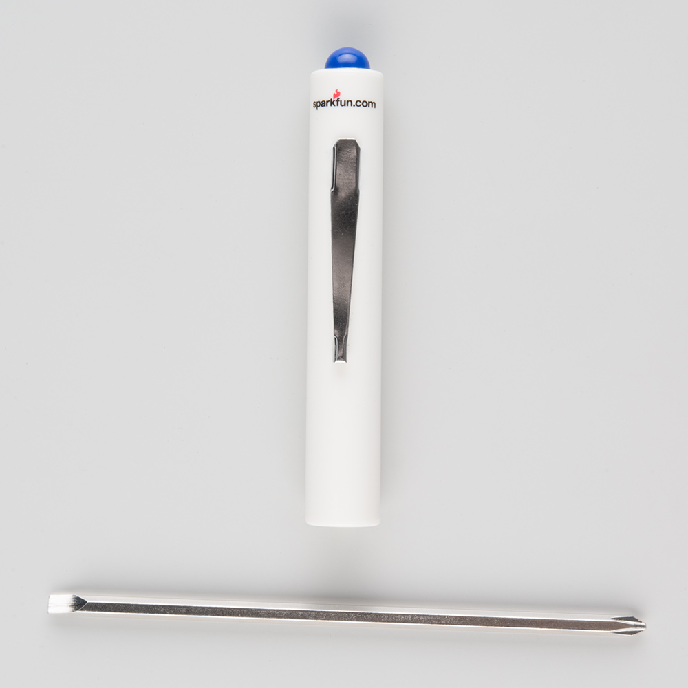
A Note About the Screwdriver
The Mini Screwdriver contains a flat-head and Phillips head. To change to the Phillips head, you might have to remove the metal shaft, turn it around, and insert it back into the plastic handle.
Prepare the Mechanical Bumpers
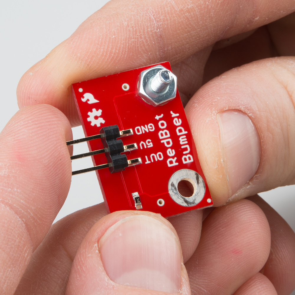
Screw a #4-40 x 3/8" screw (V) and #4-40 hex nut (X) to one of the two large mechanical bumper holes. You can get it pretty tight with just your fingers, but we've included a screwdriver screwdriver (AB) in your kit. Note that the screwdriver has both a Phillips and a regular head. Pull the screwdriver out of the handle to change the head.
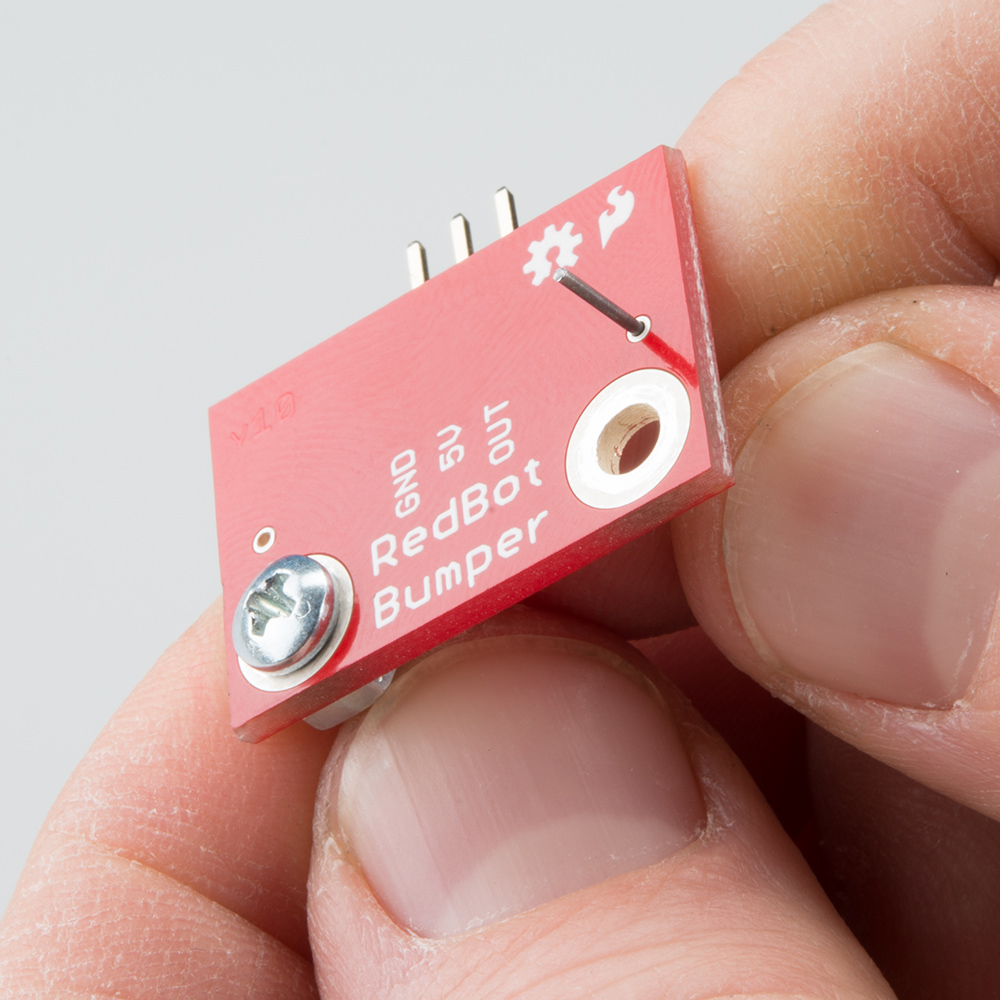
Time to bend the whisker!
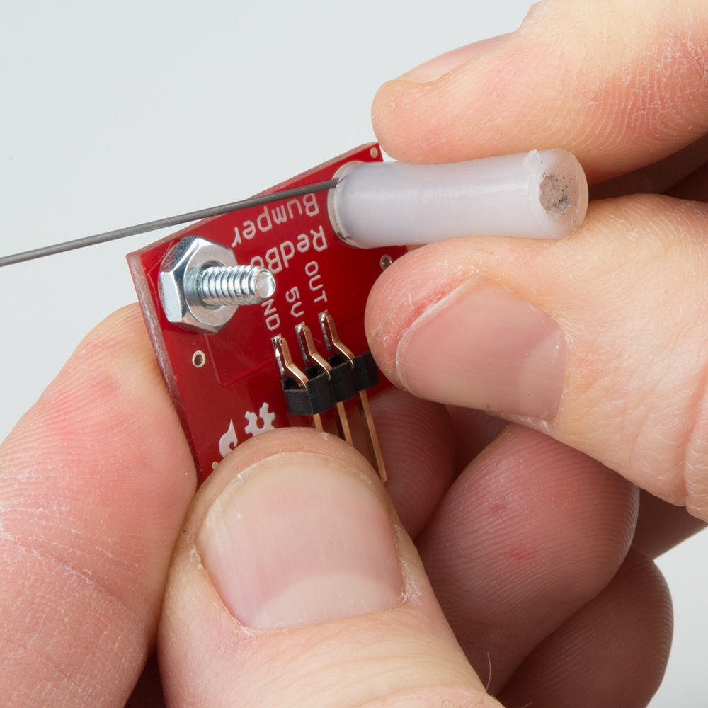
It is easy to bend the whisker using needle nose pliers. However, there is a trick to bend the whisker using the Mechanical Bumper Board itself. First, stick one of the whiskers (U) through one of the smaller side holes. It only needs to stick out a little bit.
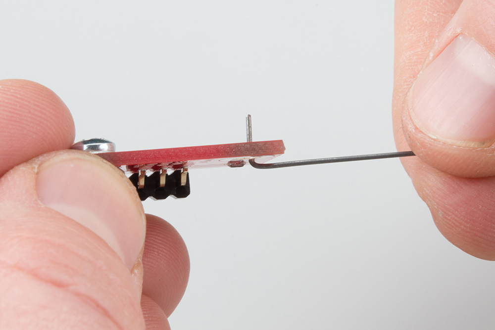
Bend the whisker 90 degrees.
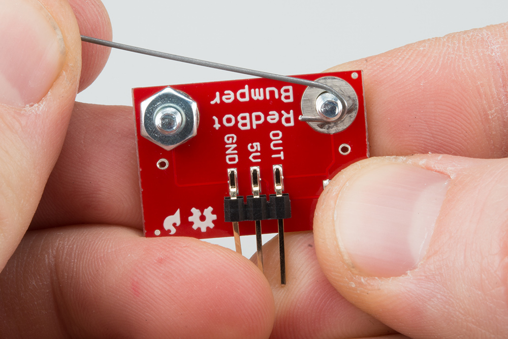
Bend the whisker 90 degrees again.

Now that the whisker is bent, take the wire out of the PCB hole. Add a #4-40 x 3/8" Screw (V) from the bottom and loop the bent whisker around the screw. Hold this tight and secure it with a the #4-40 nylon standoff.
Note: It is very important that you do not let the whisker touch the hex nut or screw on the other side. This is what triggers the sensor. Leave a little space between the wire and other side's nut.
Twist and tighten the #4-40 nylon standoff on top of the screw to secure the whisker.
Double check that the whisker does not touch the #4-40 hex nut or screw on the other side. Use the screwdriver to tighten the screw with out moving the position of the whisker.

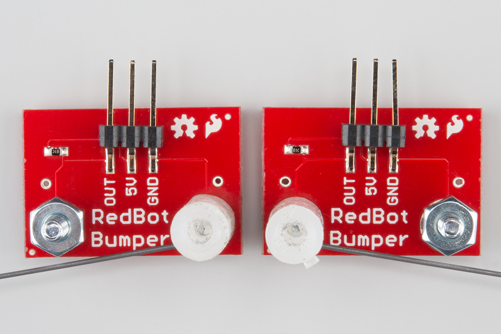
We want to opposing whiskers. Take note of which side your #4-40 x 3/4" standoff is on for the first mechanical bumper. Do the opposite for the other bumper. Double check that there is one mechanical bumper that has a #4-40 x 3/4" standoff on the right side of the "RedBot Bumper" silkscreen and one that has a #4-40 x 3/4" standoff on the left side.
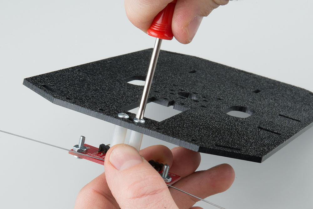
Attach the Bumpers to the Chassis
Locate the wide rectangular slot on the front of the Top Chassis Plate (B). Notice the four circular holes as well. This is the front of the chassis.
Using two #4-40 x 3/8" Screws (V), tighten down the bumper assemblies with the two wires pointing in opposite directions on the bottom side of the top chassis plate. The mechanical bumpers' header pins should be pointing toward the center of the chassis piece.
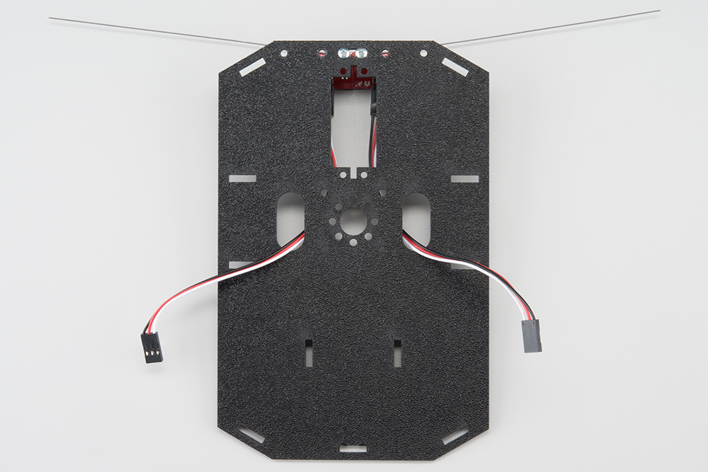
Attach the Cables
You will need to connect a 3-Wire Jumper Cable (Y) to each of the Bumper Boards (T). Note the color of the wire attached to each pin.
Bumper Connections:
| Jumper Wire Color | RedBot Sensor - Line Follower |
|---|---|
| Black | GND |
| Red | VCC |
| White | OUT |
Attach both cables to the 2 Bumper Boards.

Route the cables through the left and right oval cutouts, respectively.
5. Chassis
With the motors and a few sensors attached, we can assemble the main body of the robot.
Locate the Following:
| 4x Side Strut (E) | 1x Nub Caster (M) | |
 |
 |
You will also need the Top Chassis Plate and Bottom Chassis Plate assemblies, which have any additional parts and sensors you attached in previous steps.
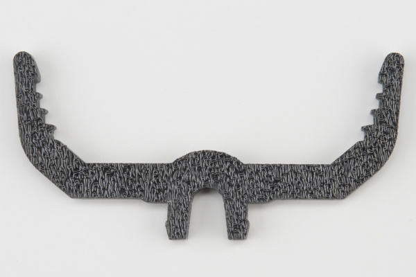
Attach the Nub Caster
Snap the Nub Caster (M) into the slot on the back of the Bottom Chassis Plate assembly. Make sure the Nub Caster is on the side opposite the motors (the bottom side).
Add the Side Struts
Snap the four Side Struts (E) into the diagonal slots on the four corners of the Bottom Chassis Plate assembly.
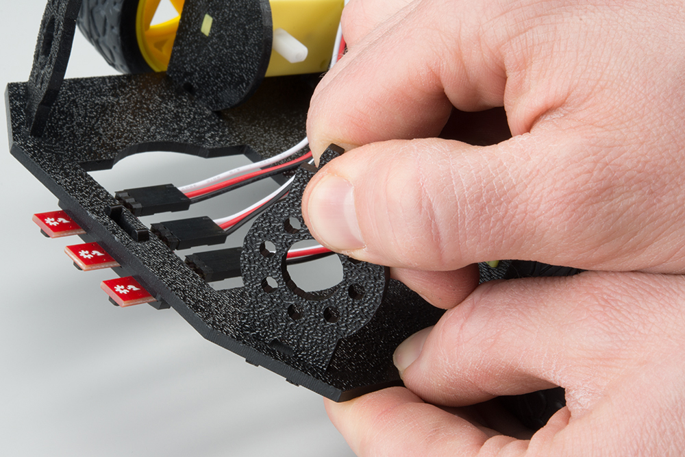
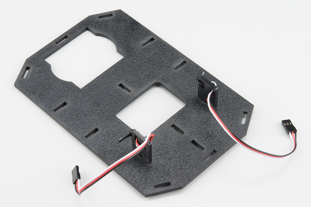
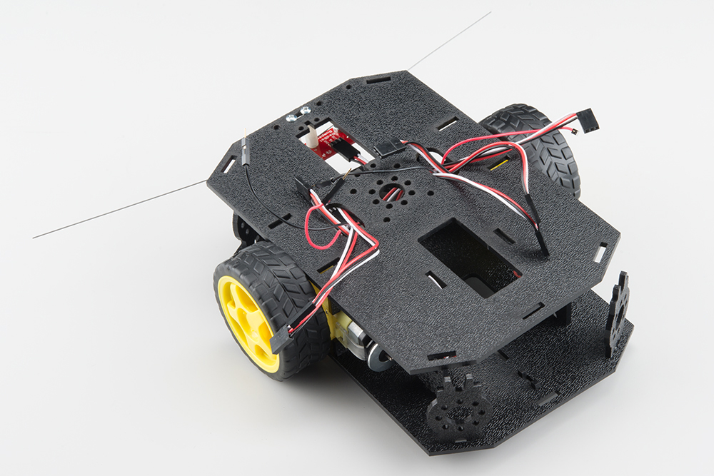
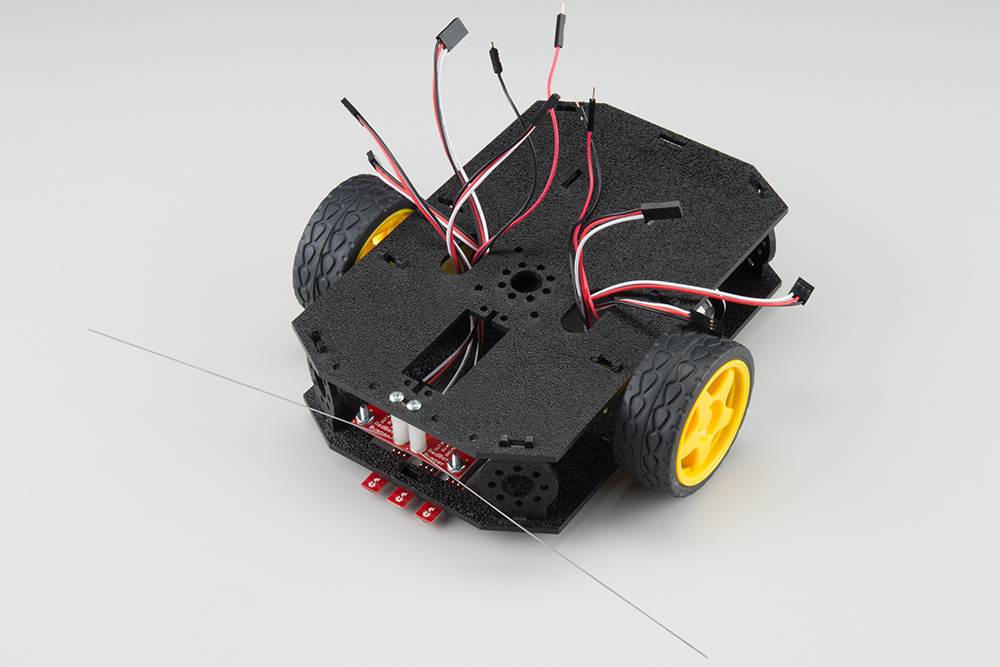
Route the Cables
Position the Top Chassis Plate over the Bottom Chassis Plate -- but do not snap the two plates together yet. Make sure that the front sides of each plate line up.
Route the wires and cables through the left and right oval slots in the Top Chassis Plate assembly as shown. For the center line follower sensor, route this cable through the right oval slot. Note that SIK-only cables are listed with an asterisk (*).
NOTE: It might be a good idea to use some pieces of masking tape to mark which cables go to which component. It's not necessary, but it might help keep things organized.
Cable Routing:
| Cable Connection | Oval Side |
|---|---|
| Left Bumper Sensor* | Left |
| Right Bumper Sensor* | Right |
| Left Line Follower | Left |
| Center Line Follower | Right |
| Right Line Follower | Right |
| Left Motor wires (red and black) | Left |
| Right Motor wires (red and black) | Right |
| Left Wheel Encoder* | Left |
| Right Wheel Encoder* | Right |
| * Indicates parts included in the SIK for RedBot | |
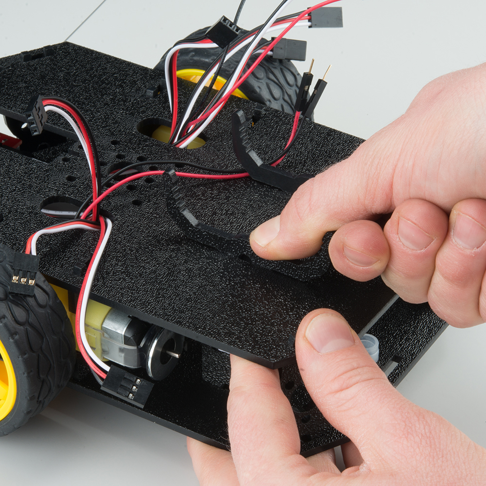
Attach Top Chassis Plate Assembly
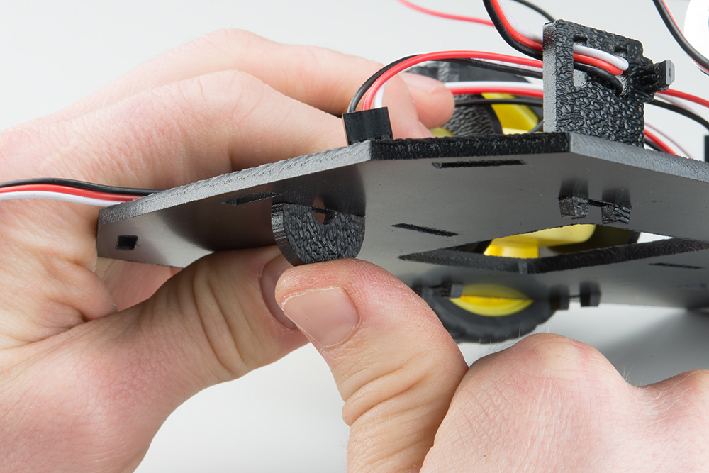
Line up the Top Chassis Plate on top of all the struts, and carefully snap the Top Chassis Plate assembly onto the side struts and motor mounts. Press gently above each side strut individually until they each snap into place. If you have the Bumpers installed, make sure the boards are between the top and bottom plates.
If you need to remove the plate to change anything, gently pull upward on each side strut individually. Do not attempt to use pliers or hand tools, or you may end up snapping the plastic clip.
6. Mainboard
In this section, you will add brains of the robot: the RedBot Mainbooard.
Locate the Following:
| 2x Mainboard Mount (G) | 1x RedBot Mainboard (P) | |
 |
 |
> |
You will also need the full chassis assembly, which contains any additional parts and sensors you attached in previous steps.
Attach the Mainboard Mounts
Snap the two Mainboard Mounts (G) into the vertical slots in the back of the top chassis plate near the large rectangular opening.
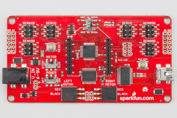
Add the Mainboard
The RedBot Mainboard (P) snaps into the lowest of the notches on the Mainboard Mounts (G). Make sure the power jack is facing the left side of the robot. Push gently and evenly until it snaps into place.
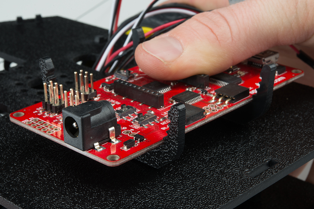
NOTE: The other slots in the mainboard mounts can be used to hold the Arduino UNO or the SparkFun RedBoard.
Connecting the Cables
It is time to connect the jumper wires; it is really important that these connections are right.
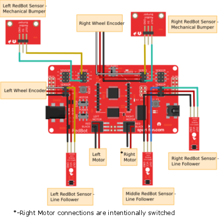
You can follow along with the pin out tables or scroll down for a diagram. Trace each cable poking through the top chassis plate to make sure you know what it is connected to.
If you have the RedBot Basic Kit, disregard any extra sensors that are missing in your kit. These sensors will be marked with the label (SIK).
Please note: When you have the RedBot upright and the front of the chassis facing away from you, "left" sensors/motors will be on the left side and "right" sensors/motors will be on the right side. Also - the motor wires are intentionally switched for the right motor -- see notes below.
Line Followers
Left Line Follower:
| RedBot Mainboard Pins | Jumper Wires | Left Line Follower Board |
|---|---|---|
| A3 | 3-Wire Jumper Cable - White | OUT |
| 5V | 3-Wire Jumper Cable - Red | VCC |
| GND | 3-Wire Jumper Cable - Black | GND |
Center Line Follower:
| RedBot Mainboard Pins | Jumper Wires | Middle Line Follower Board |
|---|---|---|
| A6 | 3-Wire Jumper Cable - White | OUT |
| 5V | 3-Wire Jumper Cable - Red | VCC |
| GND | 3-Wire Jumper Cable - Black | GND |
Right Line Follower:
| RedBot Mainboard Pins | Jumper Wires | Right Line Follower Board |
|---|---|---|
| A7 | 3-Wire Jumper Cable - White | OUT |
| 5V | 3-Wire Jumper Cable - Red | VCC |
| GND | 3-Wire Jumper Cable - Black | GND |
Whisker Mechanical Bumpers
Left Mechanical Bumper (SIK):
| RedBot Mainboard Pins | Jumper Wires | Left Bumper Board |
|---|---|---|
| 3 | 3-Wire Jumper Cable - White | OUT |
| POW | 3-Wire Jumper Cable - Red | 5V |
| GND | 3-Wire Jumper Cable - Black | GND |
Right Mechanical Bumper (SIK):
| RedBot Mainboard Pins | Jumper Wires | Right Bumper Board |
|---|---|---|
| 11 | 3-Wire Jumper Cable - White | OUT |
| POW | 3-Wire Jumper Cable - Red | 5V |
| GND | 3-Wire Jumper Cable - Black | GND |
Motors
Left Motor:
| RedBot Mainboard Pins | Left Motor Jumper Wires |
|---|---|
| LEFT MOTOR - RED | Soldered on Motor Jumper Wire - RED |
| LEFT MOTOR - BLACK | Soldered on Motor Jumper Wire - BLACK |
Right Motor:
| RedBot Mainboard Pins | Right Motor Jumper Wires |
|---|---|
| RIGHT MOTOR - RED | Soldered on Motor Jumper Wire - BLACK |
| RIGHT MOTOR - BLACK | Soldered on Motor Jumper Wire - RED |
Motor Encoders
Left Wheel Encoder (SIK):
| RedBot Mainboard Pins | Jumper Wires | Left Wheel Encoder |
|---|---|---|
| A2 | 3-Wire Jumper Cable - White | OUT |
| POW | 3-Wire Jumper Cable - Red | 5V |
| GND | 3-Wire Jumper Cable - Black | GND |
Right Wheel Encoder (SIK):
| RedBot Mainboard Pins | Jumper Wires | Right Wheel Encoder |
|---|---|---|
| 10 | 3-Wire Jumper Cable - White | OUT |
| POW | 3-Wire Jumper Cable - Red | 5V |
| GND | 3-Wire Jumper Cable - Black | GND |
Diagram
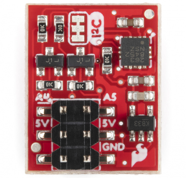
7. Accelerometer
Time to add the RedBot accelerometer! The accelerometer is a special sensor that can be used to measure speed (through acceleration), tilt (orientation), and detect jolts or bumps. If you do not have headers on your accelerometer already (older revisions of the RedBot accelerometer did not have headers), we recommend soldering on female headers to your accelerometer to fit on top of the RedBot Mainboard's headers.
Locate the Following:
| 1x Accelerometer Board (R) | ||
 |
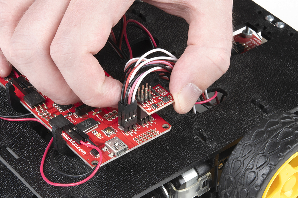
Add the RedBot Accelerometer
Locate the SENSOR port with "A4" and "A5" marked near the upper right corner of the RedBot Mainboard. Line up the "A4" pin on the accelerometer to the "A4" male header pin on the RedBot Mainboard, and attach the Accelerometer Board (R).
8. Buzzer (SIK)
Read on if you have the SIK for RedBot or are using the RedBot Buzzer. If not, skip to the next section.
Every robot should be able to make some sounds. Adding the buzzer will allow you to give your RedBot a little personality with its own beeps and bops. Adding the RedBot Buzzer is nice and easy!
Locate the Following:
| 1x Buzzer Board (S) | ||
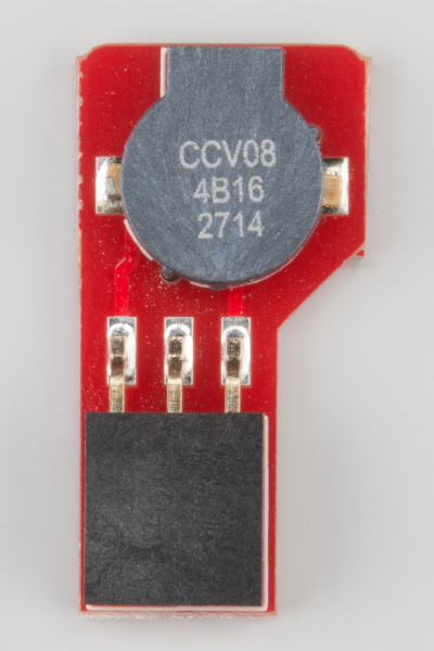 |
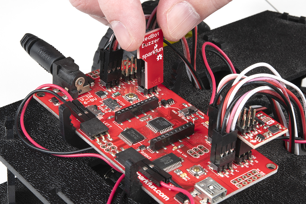
Add the RedBot Buzzer
Locate the SERVO port with "9" marked on the RedBot Mainboard. With the buzzer and female header side of the Buzzer Board (S) facing to the left, place the Buzzer Board on top of the "9", "POW", and "GND" male header pins.
9. Batteries
The last step is to provide a power source for the RedBot. If you do not have the SIK for RedBot, you will need to provide your own AA batteries.
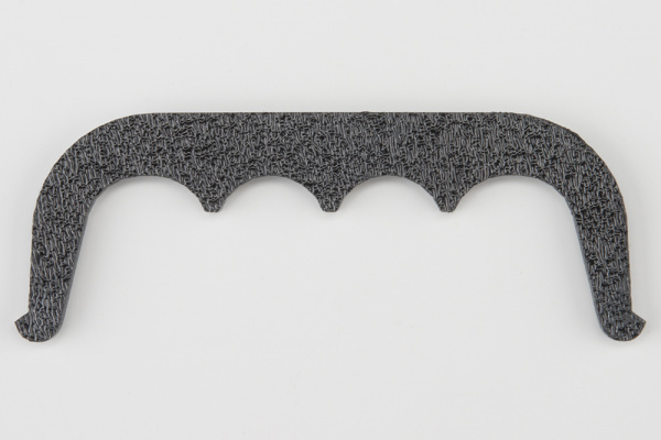
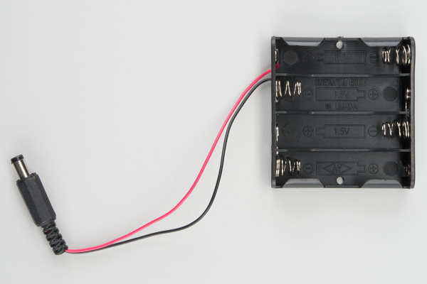
Locate the Following:
| 1x Battery Pack Clip (H) | 1x Battery Holder (Z) | 4x AA Batteries* (AA) |
 |
 |
 |
| * Provided in the SIK for RedBot | ||
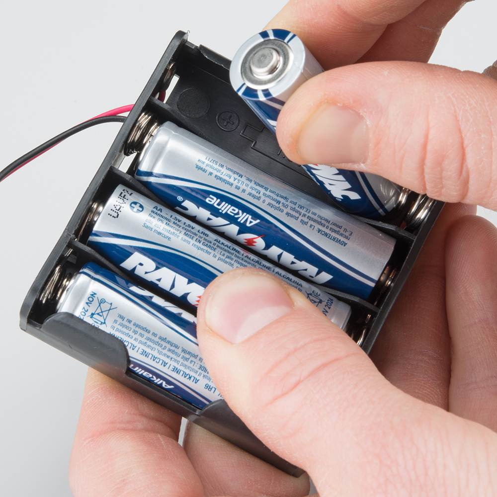
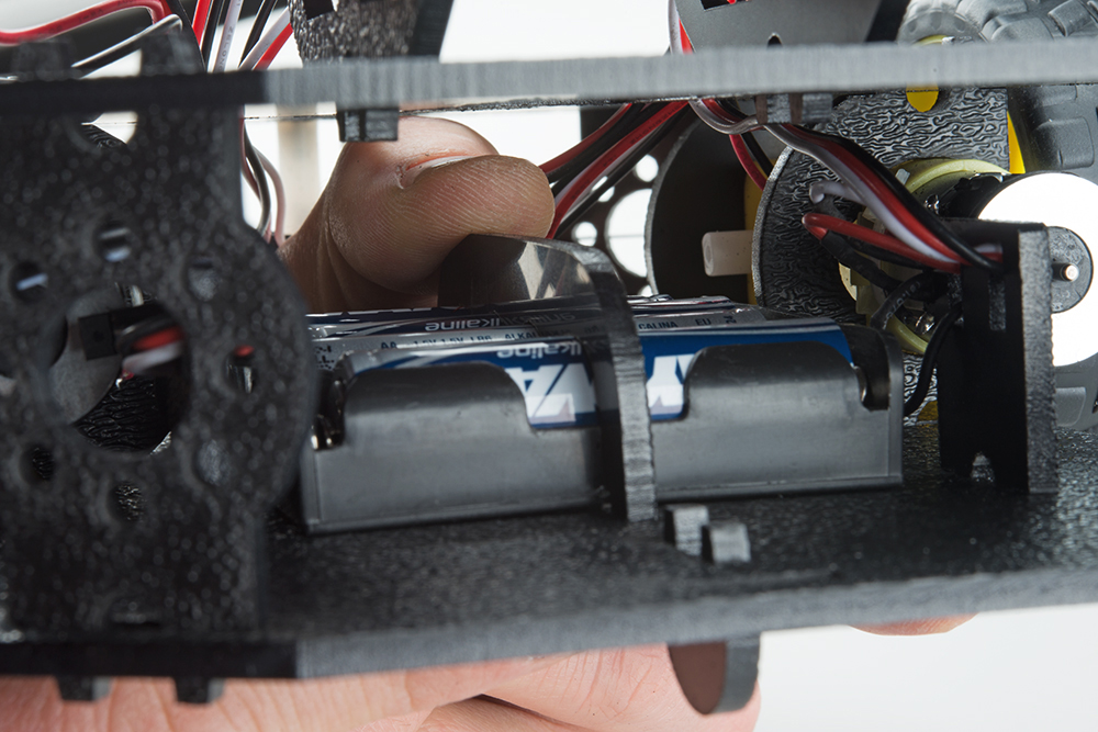
Insert Batteries
Insert the AA batteries into the Battery Holder (Z). Makes sure the batteries are facing the correct direction, as per the markings inside of the Battery Holder.
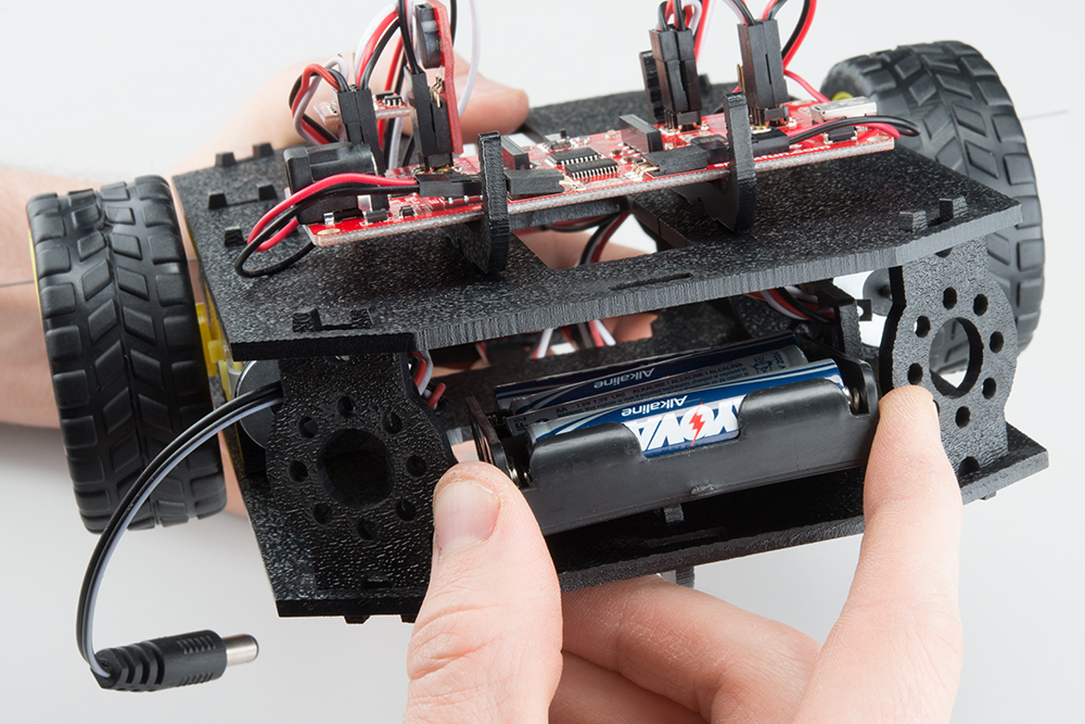
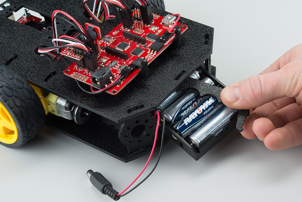
Attach Battery Pack
Insert the Battery Holder (Z) with batteries into the back cavity of the RedBot. Position the Battery Holder so that the barrel jack cable comes out on the left side of the robot.
Insert the Battery Pack Clip (H) on top of the battery pack.
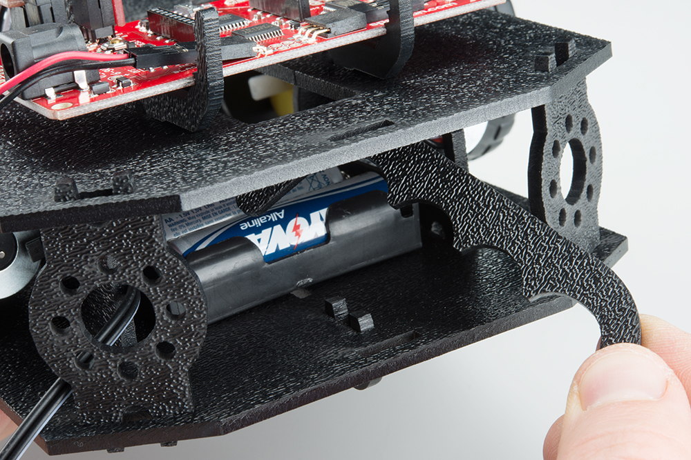
Twist and position the clip so that it rests on top of the battery pack.
Push the clip down into the vertical slots in the Bottom Chassis Plate so it snaps in place.
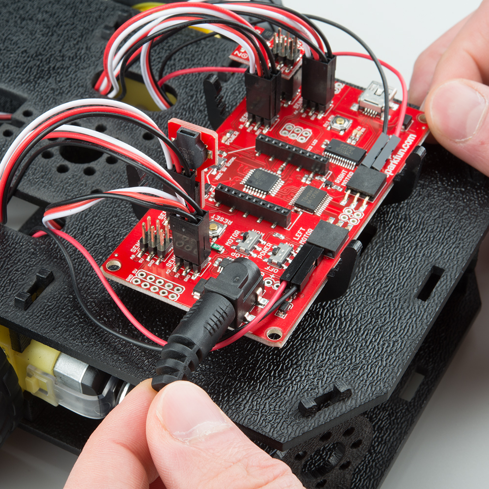
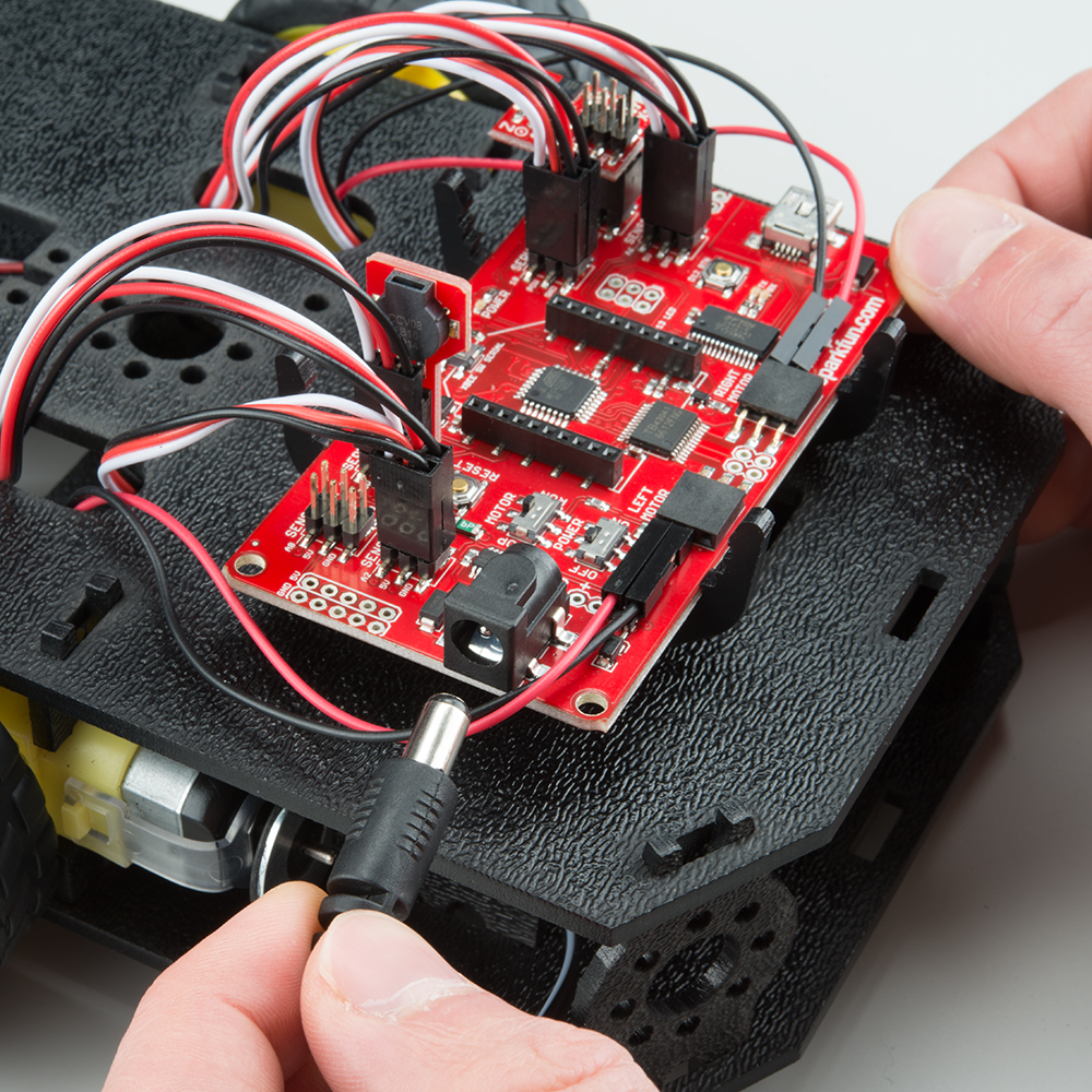
Route the barrel jack cable out of the left side of the RedBot and up to the Mainboard. If you have a motor encoder (SIK), make sure that the cable does not interfere with the magnet or the hall effect sensor.
Plug the barrel jack cable into the connector labeled V_IN.
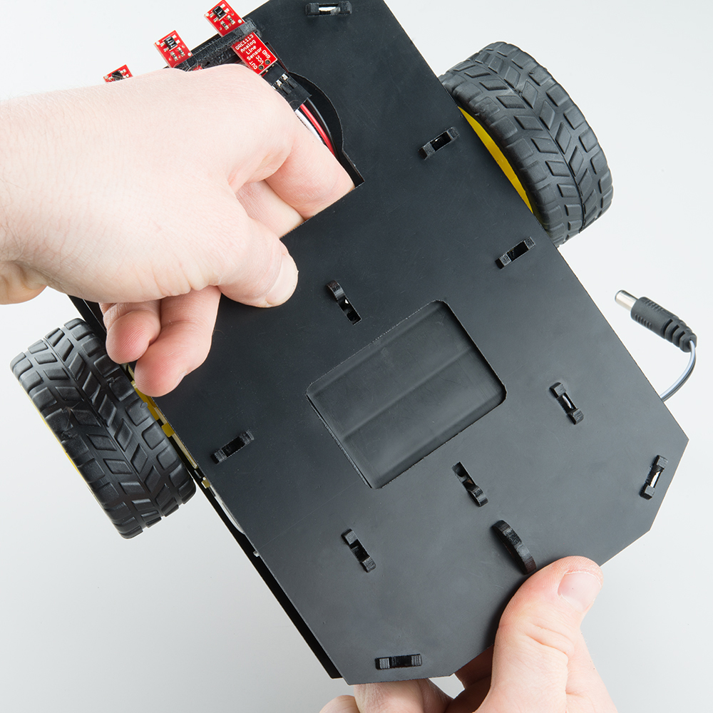
Changing the Batteries
If you find that you need to replace the batteries in the RedBot, the process is simple. Unplug the battery pack from the Mainboard.
Turn the RedBot over and push on the Battery Holder through the hole in the Bottom Chassis Plate. This will cause the Battery Pack Clip to unsnap from the Bottom Chassis Plate.
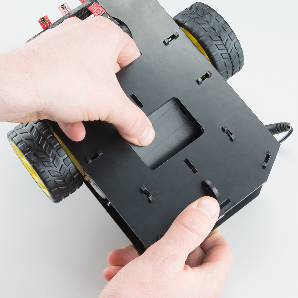
Slide the Battery Pack and Clip out from the back of the RedBot.
Change the batteries, and follow the steps in Attach Battery Pack section above to put the Battery Pack back in the RedBot.
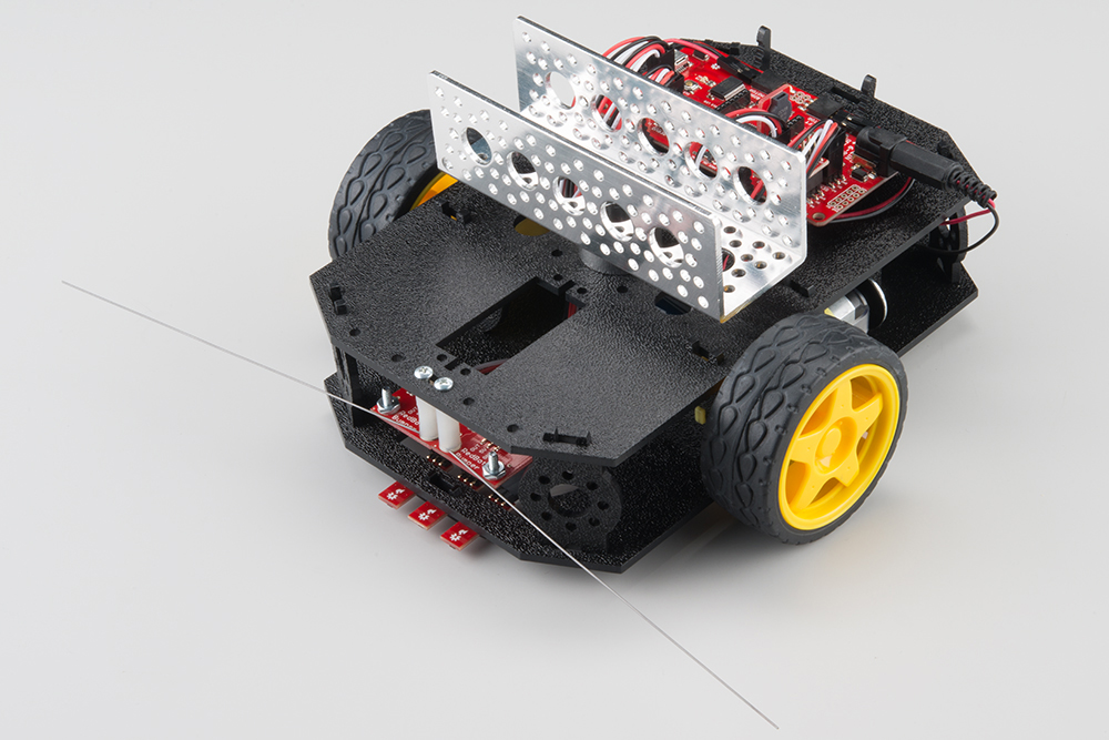
10. Run It!
Now that we have built the RedBot, we should verify that it works. If you would like a more in-depth explanation of how to program your robot, visit the Experiment Guide for RedBot with Shadow Chassis. This will work with the RedBot Basic Kit as well as the RedBot SIK.
Install Drivers
To program your robot right from your browser, you will first need to install some FTDI drivers. Follow the steps in How to Install FTDI Drivers to do that.
How to Install FTDI Drivers
June 4, 2013
Install Arduino
Note: This example assumes you are using the latest version of the Arduino IDE on your desktop. If this is your first time using Arduino, please review our tutorial on installing the Arduino IDE.
If you have not previously installed an Arduino library, please check out our installation guide.Install RedBot Library
We have written our own library to simplify the programming and interface to the RedBot motors, encoders, sensors, and other peripherals. You'll need the SparkFun RedBot Arduino Library. You can obtain these libraries through the Arduino IDE's Library Manager. Search for Sparkfun RedBot Library to install the latest version. If you prefer downloading the archived library from the GitHub repository and manually installing it, you can grab them here:
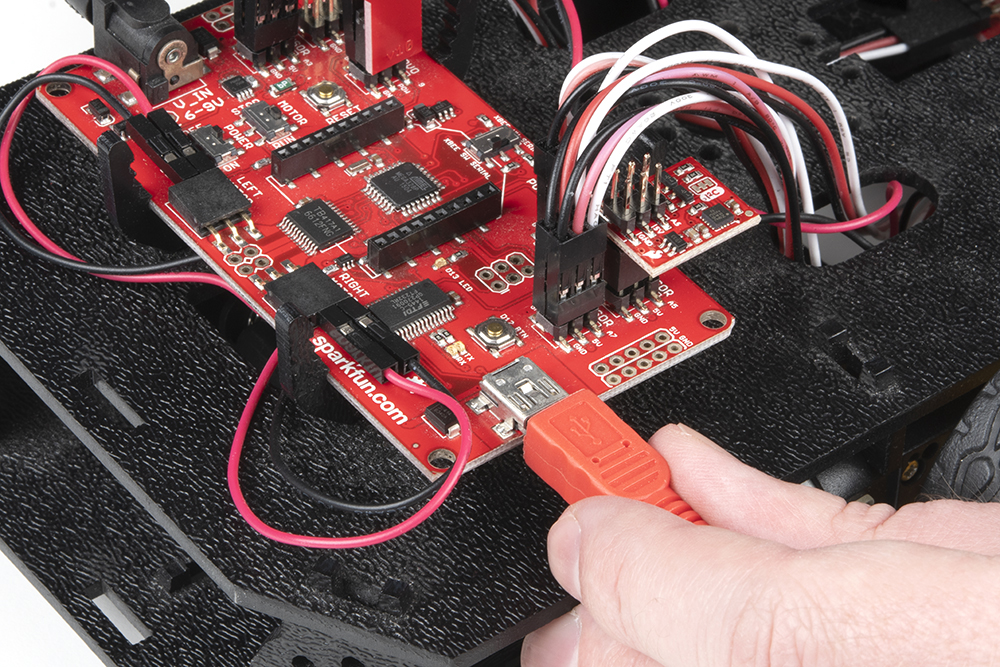
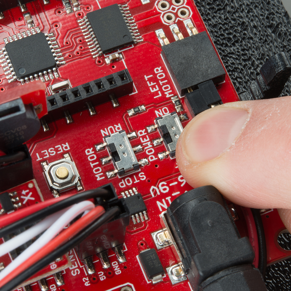
Power the RedBot
To program the RedBot, make sure you have the FTDI drivers from above installed. Plug in the RedBot using a USB mini cable.
Turn the RedBot POWER switch to ON and the MOTOR switch to RUN.
Upload Test Code
language:c
/***********************************************************************
 * Exp2_DriveForward -- RedBot Experiment 2
 *
 * Drive forward and stop.
 *
 * Hardware setup:
 * The Power switch must be on, the motors must be connected, and the board must be receiving power
 * from the battery. The motor switch must also be switched to RUN.
 *
 * 23 Sept 2013 N. Seidle/M. Hord
 * 04 Oct 2014 B. Huang
 ***********************************************************************/

#include <RedBot.h>  // This line "includes" the RedBot library into your sketch.
// Provides special objects, methods, and functions for the RedBot.

RedBotMotors motors; // Instantiate the motor control object. This only needs
// to be done once.

void setup()
{
  motors.drive(255);   // Turn on Left and right motors at full speed forward.
  delay(2000);         // Waits for 2 seconds
  motors.stop();       // Stops both motors
}

void loop()
{
  // Nothing here. We'll get to this in the next experiment.
}
In the Arduino IDE, select "Arduino UNO" for the board. Select COM port for the RedBoard (this will be the number or name that appears when you plug in the RedBoard). Then click upload.
WARNING: If the MOTOR switch is set to RUN, the RedBot will move forward (quite rapidly) for 2 seconds. You might want to pick the RedBot up so that it doesn't run away from you!
The RedBot will drive forward for only 2 seconds and then stop. If you want to run the code again, you will need to press the RESET button on the RedBot Mainboard.
Resources and Going Further
What a rock star! With all that building, we bet you are ready to start cruising. We recommend continuing to the Experiment Guide for RedBot with Shadow Chassis to learn how to program your new robot friend.
Experiment Guide for RedBot with Shadow Chassis
May 28, 2015
Upgrades
You might have noticed some odd-looking hole patterns in the top plate and side struts. The RedBot's chassis is manufactured to accept Actobotics parts. Feel free to add other mounts, gimbals, servos, and claws!
Resources
GitHub repositories: