Assembly Guide for SparkFun JetBot AI Kit V2.0
 Evan_Double_U
3. Accessory Installation to Main Chassis
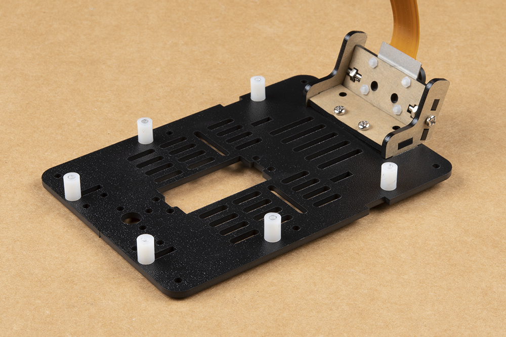
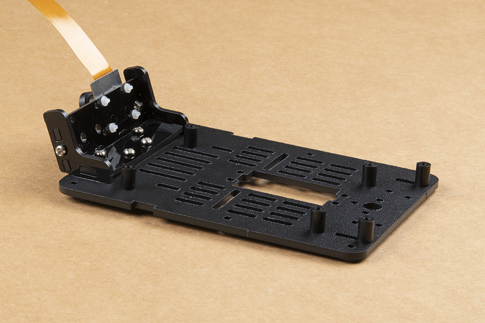
Install the included nylon standoffs using the included 4-40 screws (10 packs) on the top mounting plate (the one we just finished attaching our camera and mount to). Pictured below are the standoffs for the Jetson Nano Dev Kit, the SparkFun Qwiic Motor Driver, and SparkFun Qwiic OLED. Be sure to keep the standoffs on the right side somewhat loose. The mounting holes in the top plate are oblong to compensate for manufacturing tolerances & ensure a secure fit to the Jetson Nano Dev Kit.

The following instructions for battery installation will be the same for all Jetbot versions.
Cut the strip of dual lock Velcro into two roughly equal sized strips.
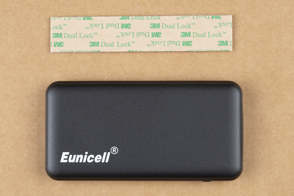
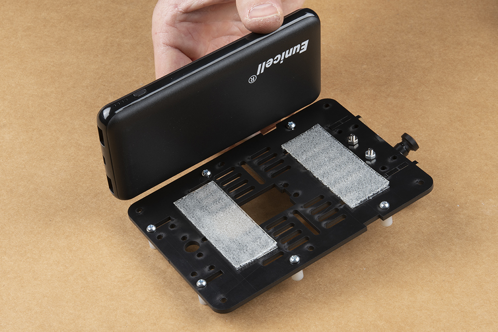
We figured you could handle this, but we already had the camera all set up & scissors in hand... Take one side of the dual lock Velcro and attach to the top of the chassis as shown.

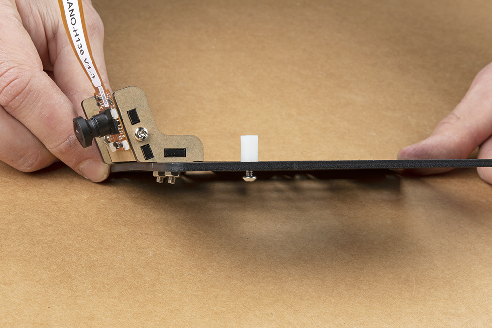
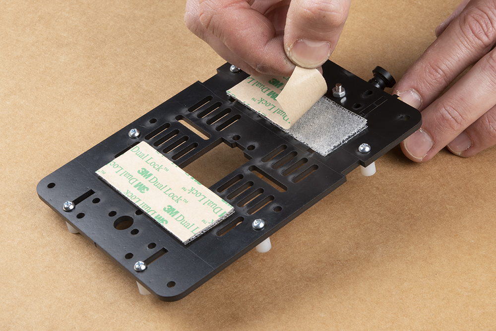
Place the corresponding pieces of dual lock Velcro on the chassis assembly top plate as pictured. Please ensure that all standoffs for the Jetson Nano & Qwiic boards are already installed on the chassis top plate; see photo. Additionally, ensure that the camera mount has been attached to the top plate as well. This will ensure that the battery does not physically hit any mounting screws.

Remove the protective film from the Dual Lock and try not to touch the sticky part.
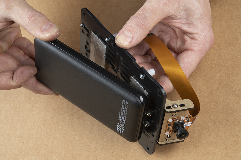
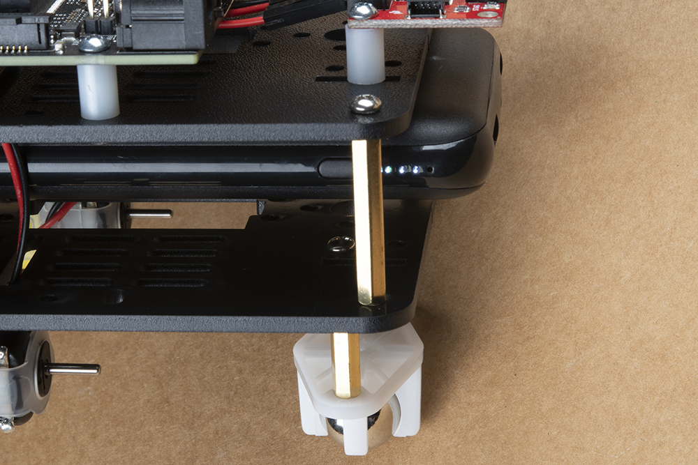
Line up the battery pack as shown to ensure correct orientation of the USB ports & no interference between the battery pack and mounting hardware.
This photo shows how to place the battery pack to not touch the camera mount hardware while not extending too far out the back of the SparkFun JetBot.
Press firmly on the battery pack to attach the dual lock Velcro interface between the chassis and battery.
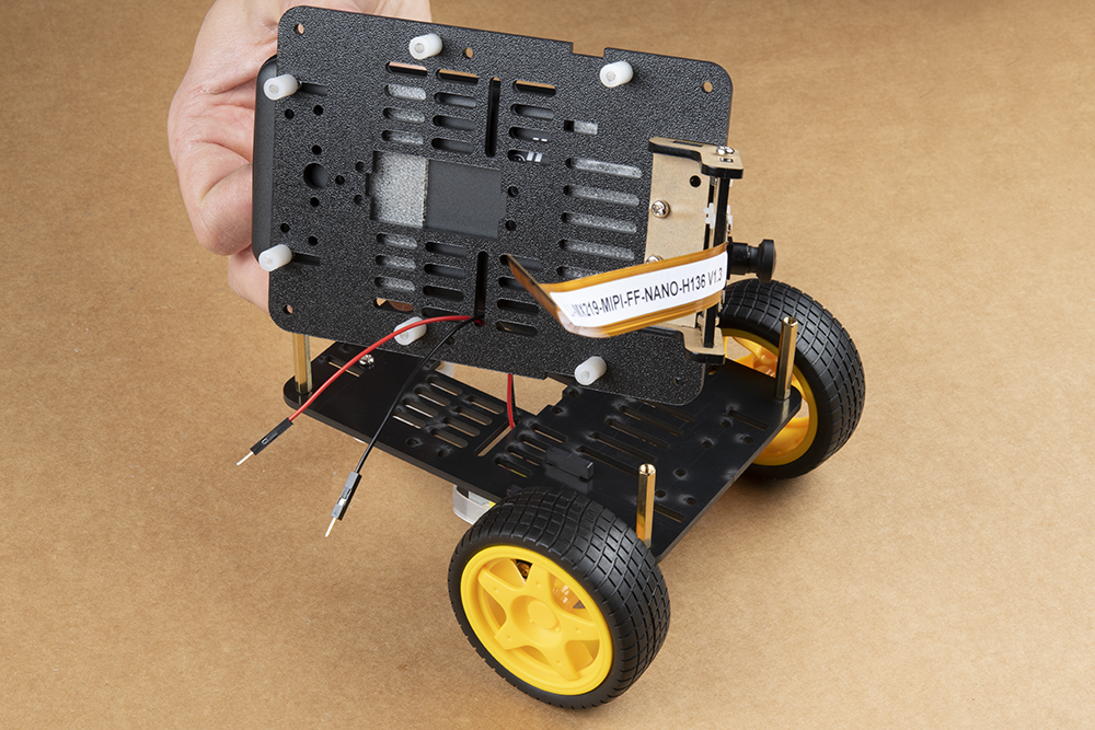
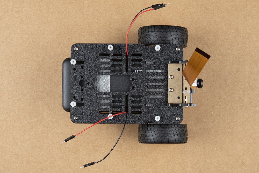
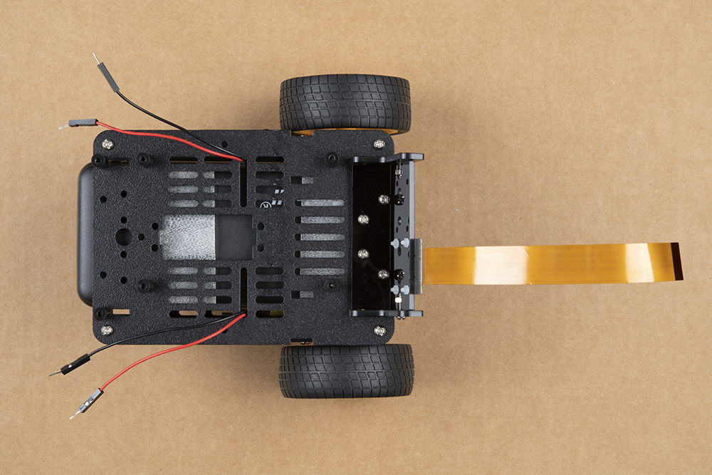
Route one set of motor leads at a time through the chassis top plate as shown.
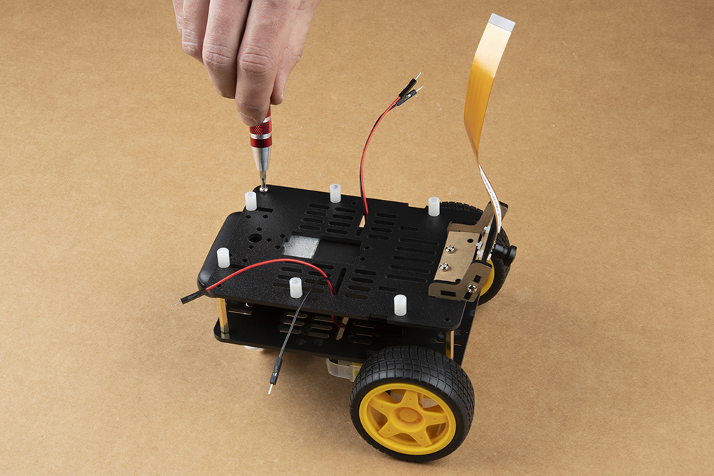
Attach the top plate to the base plate brass standoffs using the four remaining screws from the JetBot chassis kit.
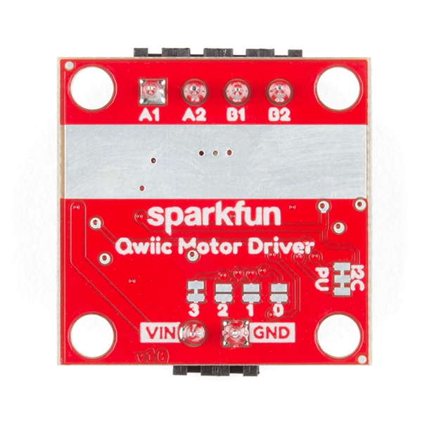
Once the chassis is fully assembled, attach the SparkFun Qwiic Motor Driver as shown using the mounting hole on the board to the right of the 4x motor screw terminal. Attach the motor leads as pictured; see below for more details.
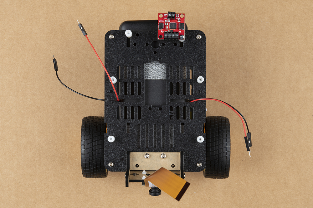
Connect the motor leads according to the table below; remember the "Right" & "Left" designations from the Introduction. They should match the image above. The right motor is on the right side of this photo.
| A1 | A2 | B1 | B2 |
|---|---|---|---|
| Left Motor Ground (-) | Left Motor Power (+) | Right Motor Ground (-) | Right Motor Power (+) |
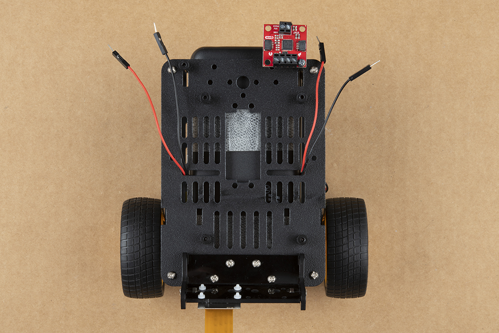
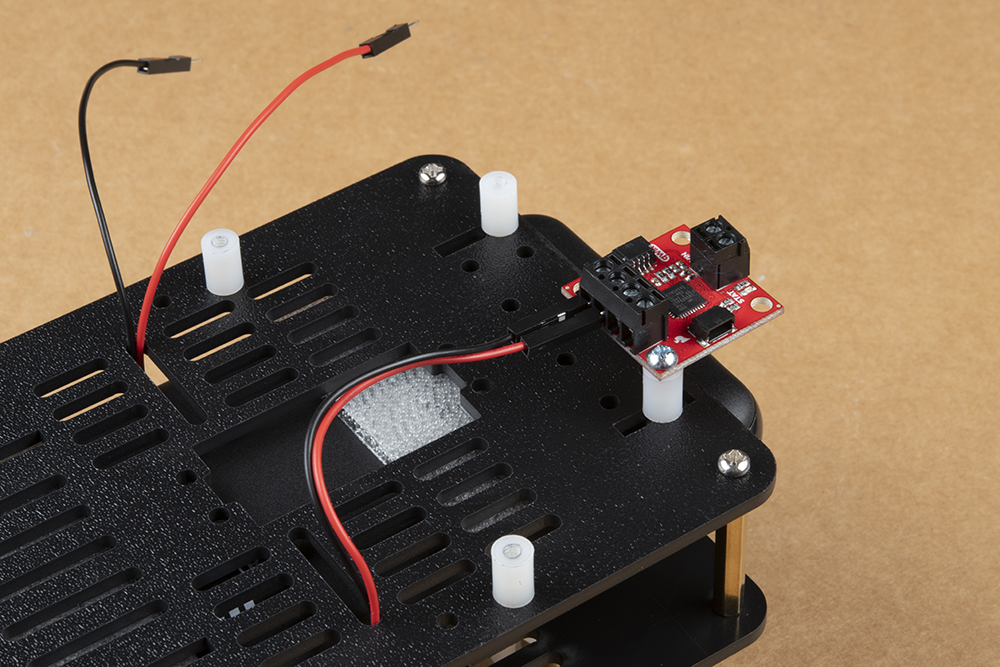
Shown below: Left motor hookup to Qwiic Motor Driver screw terminals.
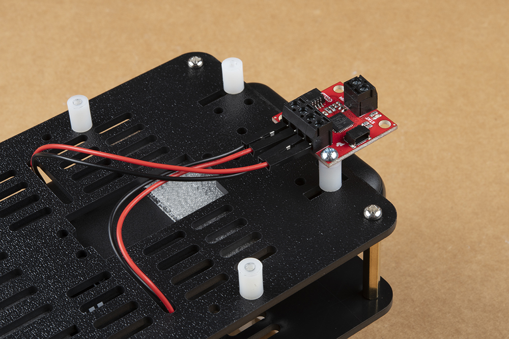
Shown below: Right motor hookup to Qwiic Motor Driver screw terminals.
Install the Edimax USB WiFi & Bluetooth Adapter into one of the USB ports on the Jetson Dev Kit.
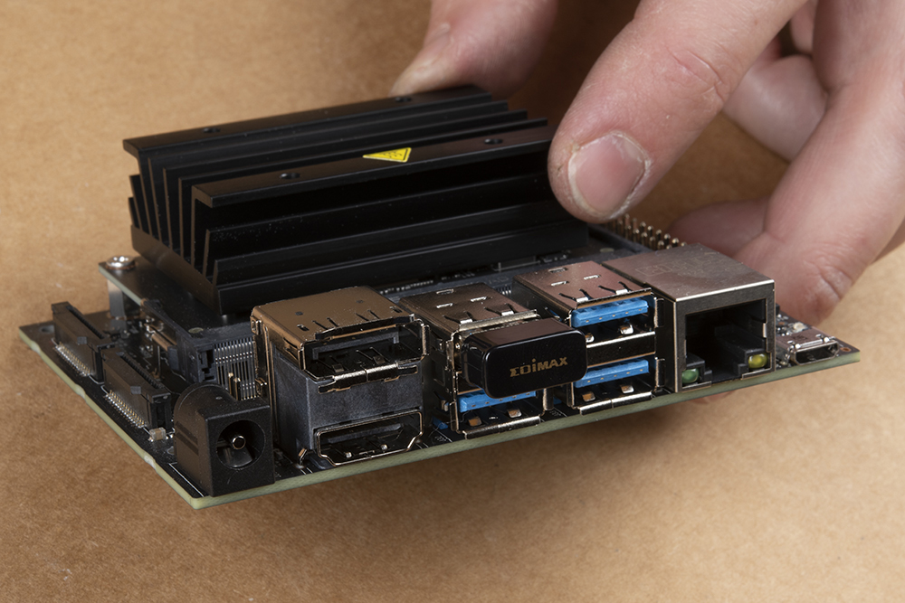
For the Jetson Nano 2GB a WiFi adaptor is included. Install the adaptor into one of the USB ports.
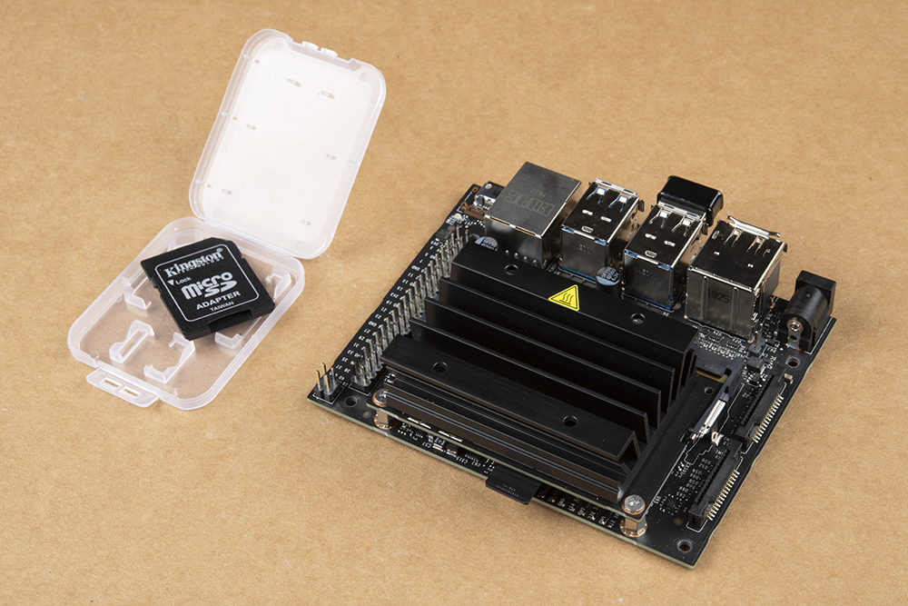
Remove the MicroSD card with the SparkFun JetBot Image (pre-flashed) from the included case & adapter and place it into the MicroSD card slot on the Jetson Nano module. It is easier to do this prior to installing the Jetson Nano Dev Kit onto the chassis and with the Dev Kit upside down as pictured, but you do you.

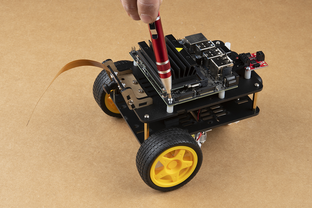
Attach the Jetson Nano Dev Kit using four 4-40 screws to the previously installed Nylon standoffs. Remember we left the right side standoffs loose so align them with the mounting holes on the Jetson Nano Dev Kit & tighten until sung.

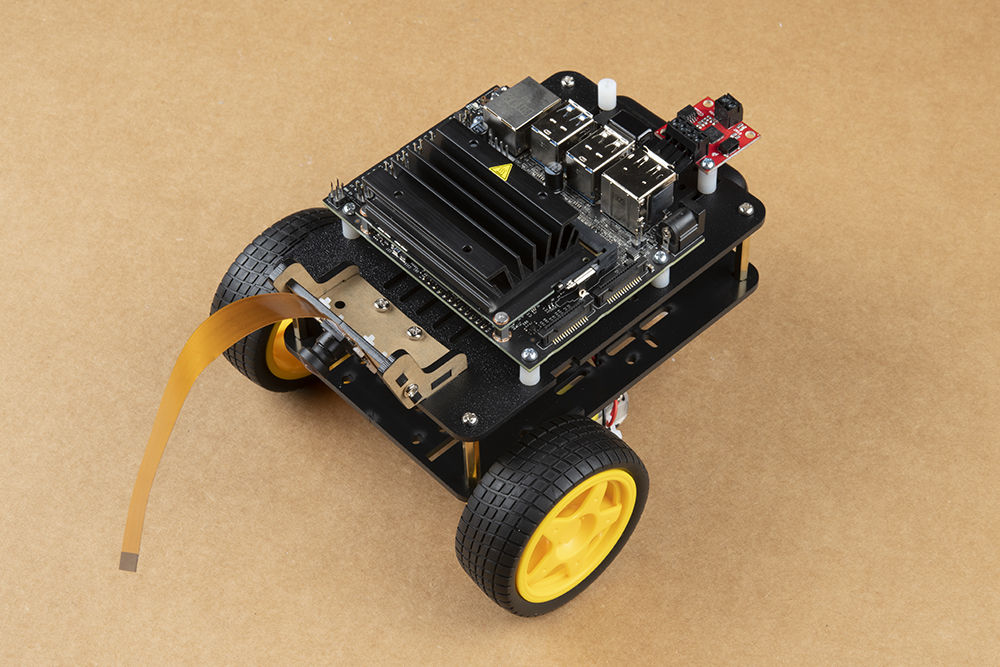
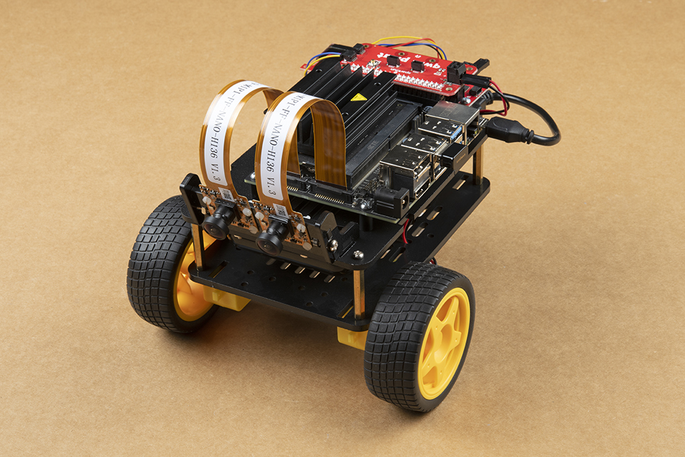
Attach the Leopard imaging camera ribbon cable as shown to the Jetson Dev Kit. This half helix ensures the contacts on the ribbon cable attach to the contact on the Jetson Dev Kit camera connector.

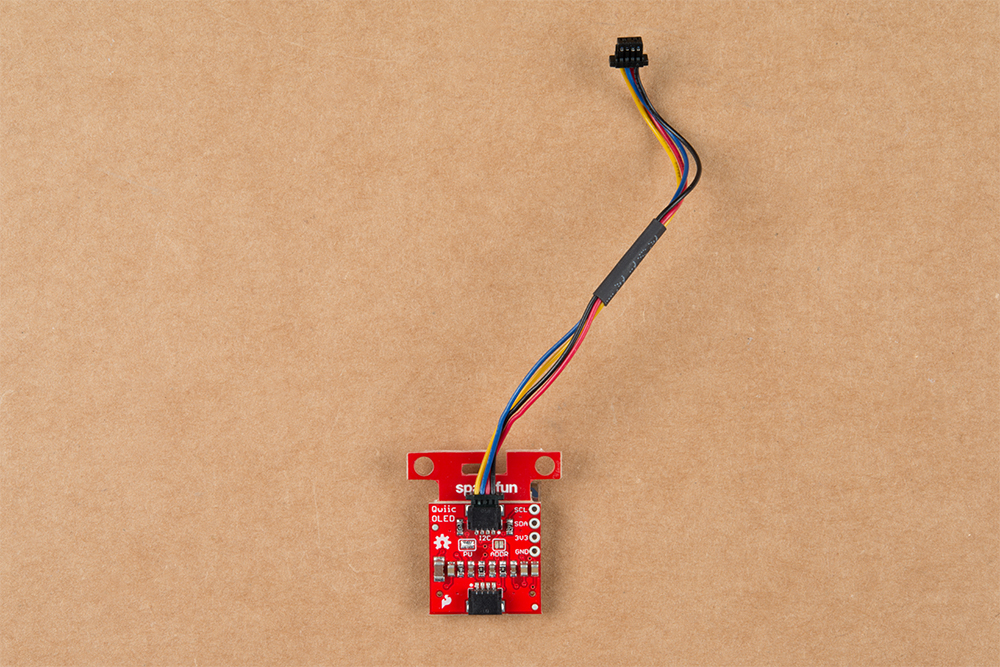
Attach the 100mm Qwiic cable to the underside of the SparkFun Qwiic Micro OLED as shown below.
Attach the SparkFun Qwiic Micro OLED to the JetBot Chassis using another Nylon Standoff & 4-40 screw. Attach the 100mm Qwiic cable to the SparkFun Qwiic Motor Driver. Secure the Qwiic Micro OLED by tightening the screw until sung.
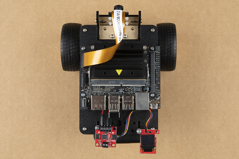
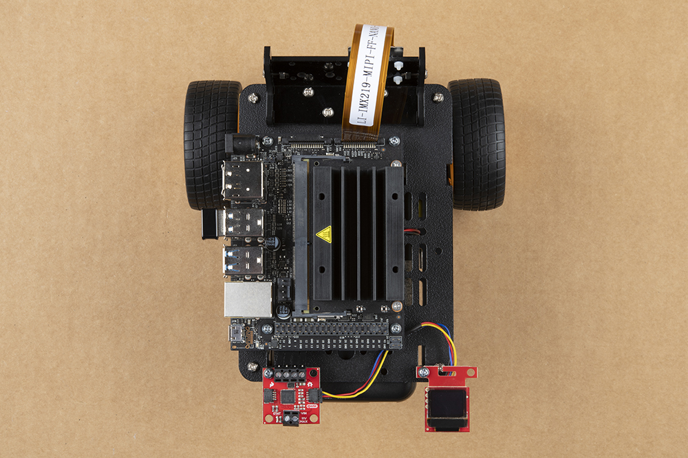
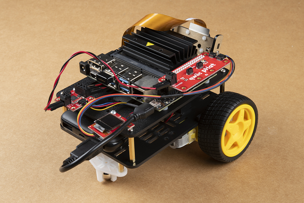
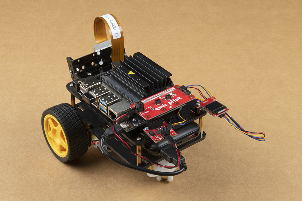
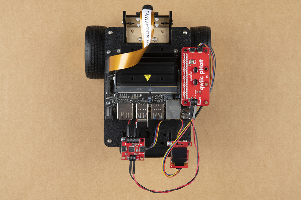
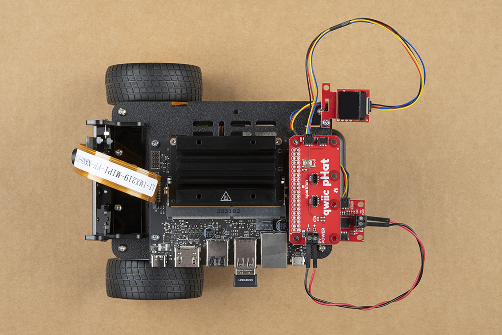
Connect the qwiic pHAT on the Jetson Nano Dev Kit's 2x20 GPIO header taking care to align it as the photo below shows. Additionally, connect the SparkFun Qwiic Micro OLED display to the Qwiic pHAT using the 200mm Qwiic cable.

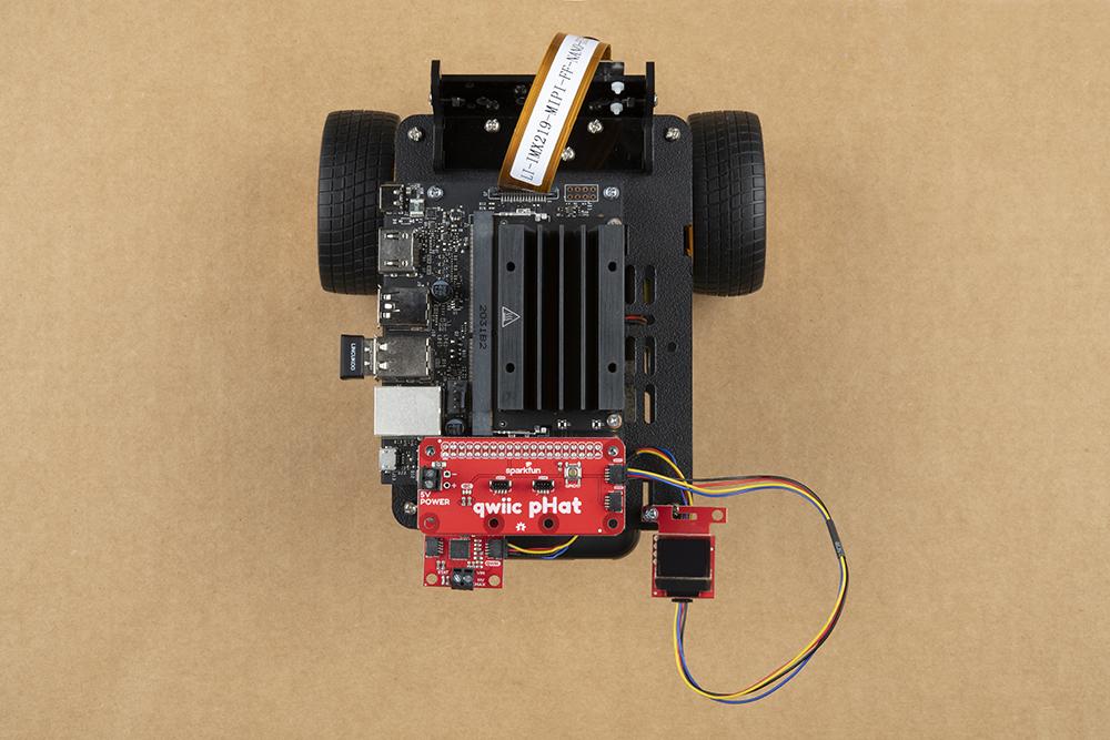
Finally attach the Qwiic Motor Driver's motor power screw terminals to the 2 pin screw terminal for 5V and Ground on the Qwiic pHAT using the included 6 inch M/M jumper wires. We recommend using one black wire (ground) & one red wire (power), but you can use any included color your head desires.
Check the battery power on the USB pack by pressing the power button on the side of the battery. Four dots means it is fully charged. The Jetson is fairly power hungry. We recommend only powering up your SparkFun JetBot with a fully charged battery pack.
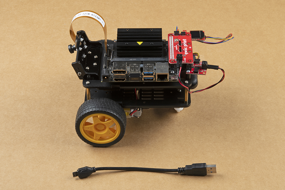
Use the included 6 inch USB Micro-B Cable to connect the Jetson Nano Dev Kit to the battery pack.

Note: Make sure the USB cable is plugged into the orange USB port (shown closest to the USB cable in the above photo) on the battery pack. This will provide the required 3.1A @ 5V required by the Jetson Nano Dev Kit.
In the new revision of the battery pack, both USB ports on the battery pack are orange. We recommend using the USB port that is on the opposite side of the power button. Otherwise, we have found that the other USB port can cause the Jetson Nano Dev kit to brown out during its boot sequence.
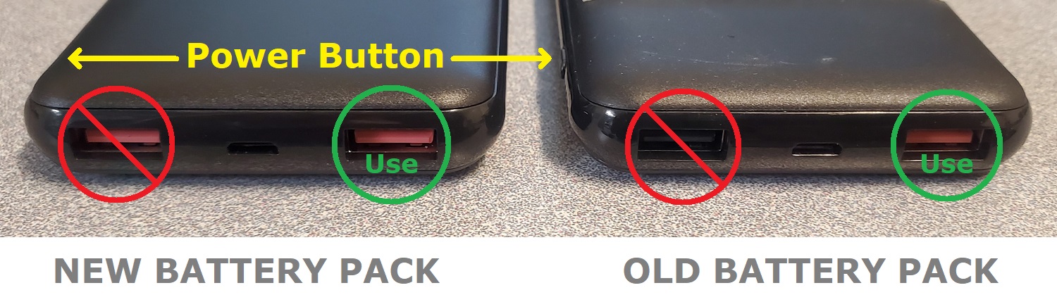
USB ports on the battery pack. (Click to enlarge)

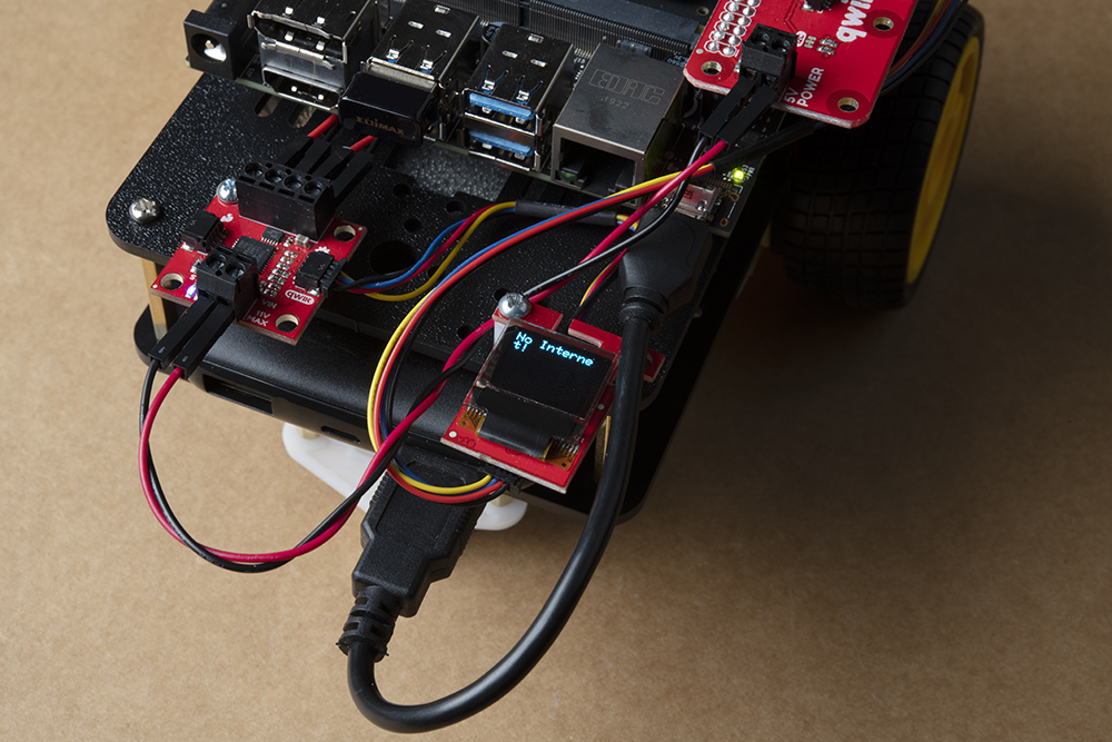
If the Jetson Nano does not power on once your USB cable is connected, press the power button the battery pack to turn the JetBot on. Allow the JetBot a few minutes to power up. When the JetBot is ready, the Micro OLED will display the SparkFun flame logo followed by the available disk image space & IP address once connected to a WiFi network; see example photos below.


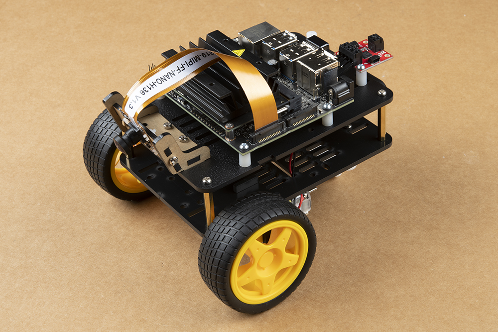
Congratulations! Your SparkFun JetBot is now fully assembled!