Assembly Guide for SparkFun JetBot AI Kit V2.0
 Evan_Double_U
Introduction
SparkFun’s multiple Jetbot offerings merge the industry leading machine learning capabilities of the NVIDIA Jetson Nano with the vast SparkFun ecosystem of sensors and accessories. Packaged as a ready-to-assemble robotics platform, the SparkFun JetBot AI Kit v2.0 requires no additional components or 3D printing to get started - just assemble the robot, boot up the Jetson Nano, connect to WiFi and start using the JetBot immediately. This combination of advanced technologies in a ready-to-assemble package makes the SparkFun JetBot Kit a standout, delivering one of the strongest robotics platforms on the market. This guide serves as hardware assembly instructions for the JetBot AI Kit v2.0. The SparkFun JetBot comes with a pre-flashed micro SD card image that includes the Nvidia JetBot base image with additional installations of the SparkFun Qwiic Python library, Edimax WiFi driver, AWS RoboMaker ready with AWS IoT Greengrass, and of course the JetBot ROS. Users only need to plug in the SD card and set up the WiFi connection to get started.
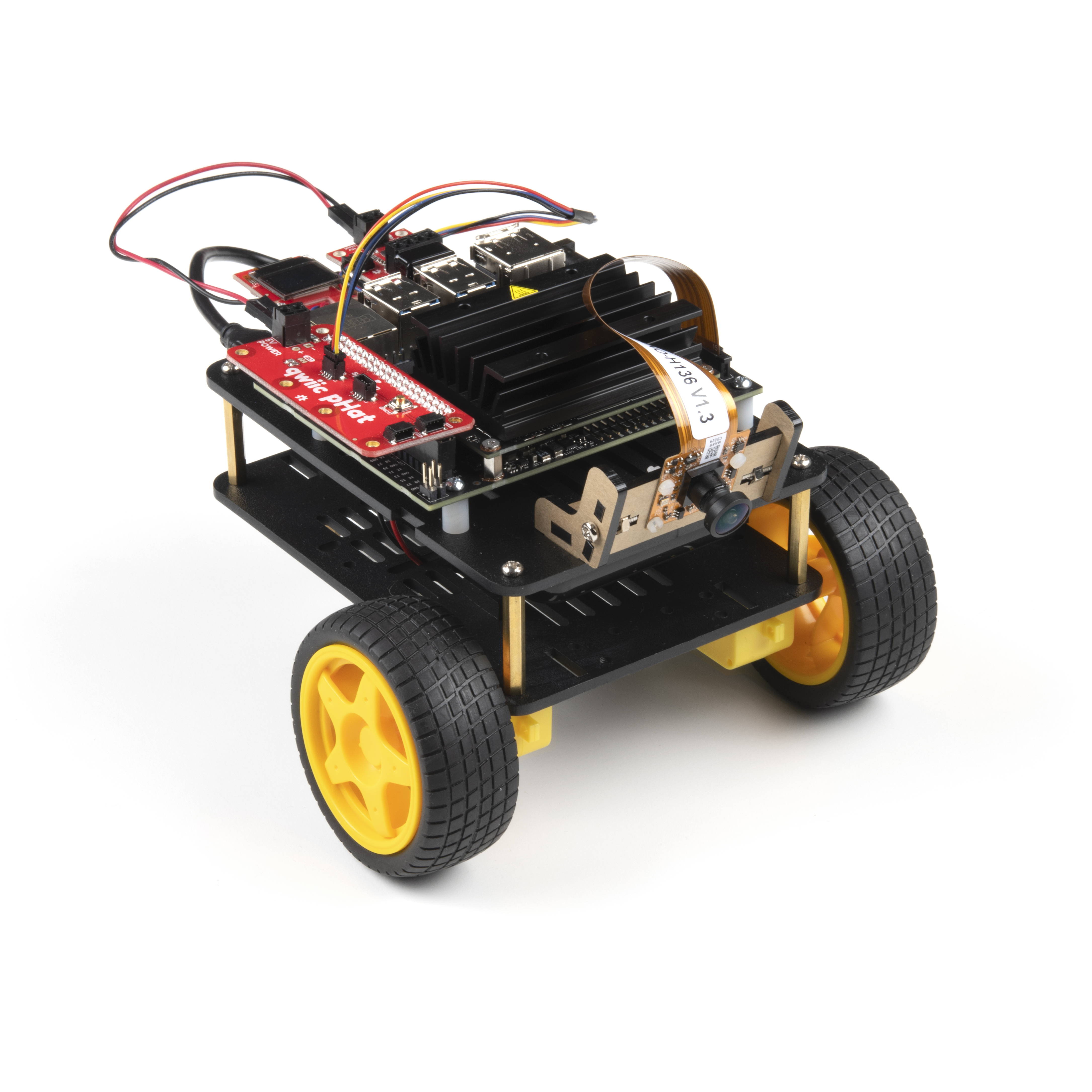
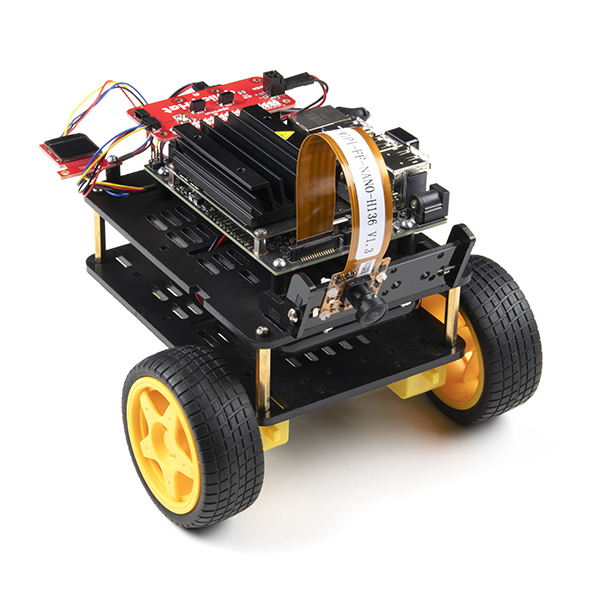
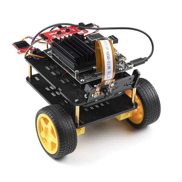
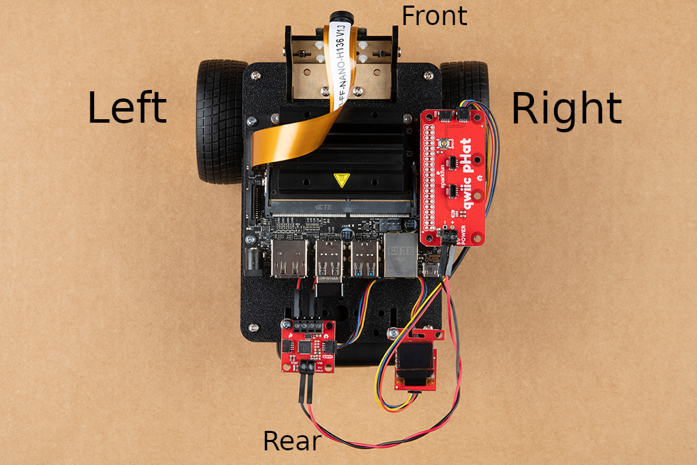
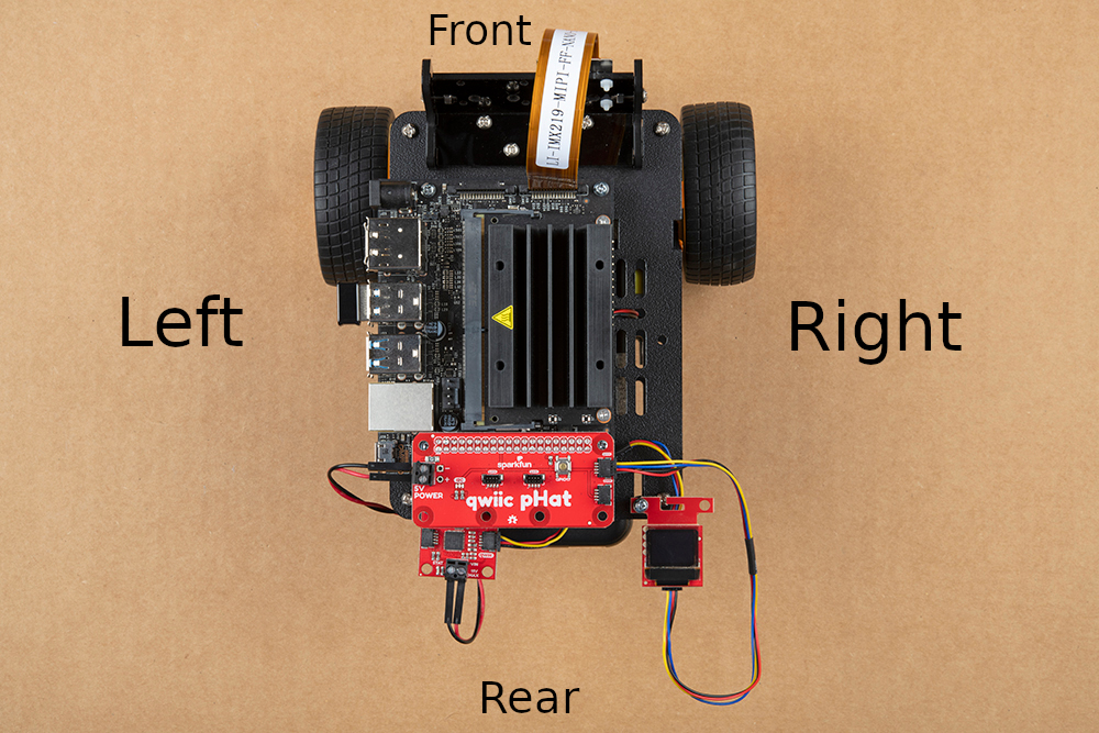
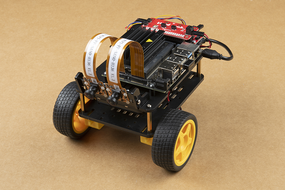
SparkFun has released several version of the Jetbot. Please make note of the comments under some photos to ensure it related to the Jetbot kit you have purchased. Completed Jetbot photos are shown below for comparison.
- SparkFun JetBot AI Kit v2.0 - Purchase before Dec 2020
- SparkFun JetBot AI Kit v2.1 - 4GB Jetson Nano Dev kit - Dec 2020 and later
- SparkFun JetBot AI Kit Powered by Jetson Nano 2GB
Attention: The SD card in this kit comes pre-flashed to work with our hardware and has the all the modules installed (including the sample machine learning models needed for the collision avoidance and object following examples). The only software procedures needed to get your JetBot running are steps 2-4 from the Nvidia instructions (i.e. setup the WiFi connection and then connect to the JetBot using a browser). Please DO NOT format or flash a new image on the SD card; otherwise, you will need to flash our image back onto the card.
If you accidentally make this mistake, don't worry. You can find instructions for re-flashing our image back onto the SD card in the Software Setup section of this guide
The Jetson Nano Developer Kit offers extensibility through an industry standard GPIO header and associated programming capabilities like the Jetson GPIO Python library. Building off this capability, the SparkFun kit includes the SparkFun Qwiic pHAT for Raspberry Pi, enabling immediate access to the extensive SparkFun Qwiic ecosystem from within the Jetson Nano environment, which makes it easy to integrate more than 30 sensors (no soldering and daisy-chainable).
The SparkFun Qwiic Connect System is an ecosystem of I2C sensors, actuators, shields and cables that make prototyping faster and less prone to error. All Qwiic-enabled boards use a common 1mm pitch, 4-pin JST connector. This reduces the amount of required PCB space, and polarized connections mean you can’t hook it up wrong.
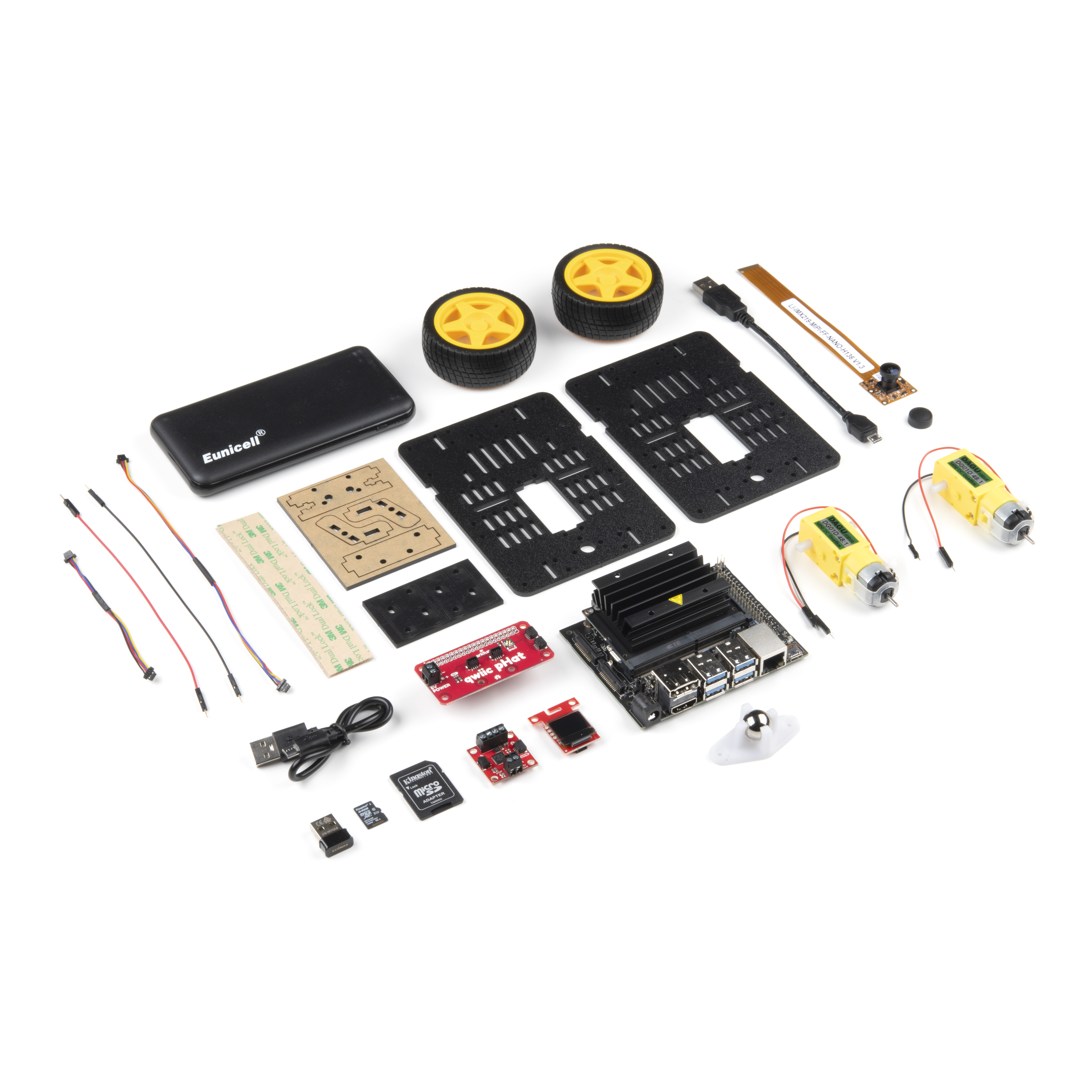
Materials
| Part | Qty |
|---|---|
| JetBot Chassis Kit | 1 |
| Hobby Gearmotor (pair) included as part of JetBot Chassis Kit | 1 |
| Camera mount included as part of JetBot Chassis Kit | 1 |
| Wheels & Tires - included as part of JetBot Chassis Kit | 2 |
| Lithium Ion Battery Pack - 10Ah (3A/1A USB Ports) | 1 |
| Edimax 2-in-1 WiFi and Bluetooth 4.0 Adapter *not included in 2GB Jetbot* | 1 |
| Jetson Dev Kit *Specific Jetson Dev Kit only included in specified Kits* | 1 |
| SparkFun JetBot image (Pre Flashed) | 1 |
| Leopard Imaging 136 FOV Camera | 1 |
| SparkFun Micro OLED Breakout (Qwiic) | 1 |
| SparkFun Qwiic Motor Driver | 1 |
| SparkFun Qwiic pHAT v2.0 for Raspberry Pi | 1 |
| Qwiic Cable - 100mm | 1 |
| Qwiic Cable - 200mm | 1 |
| Jumper Wires Premium 6" M/M (2-pack black & red) | 1 |
| USB Micro-B Cable - 6" *Jetbot 2GB includes USB-C cable for power* | 1 |
| Dual Lock Velcro | 1 |
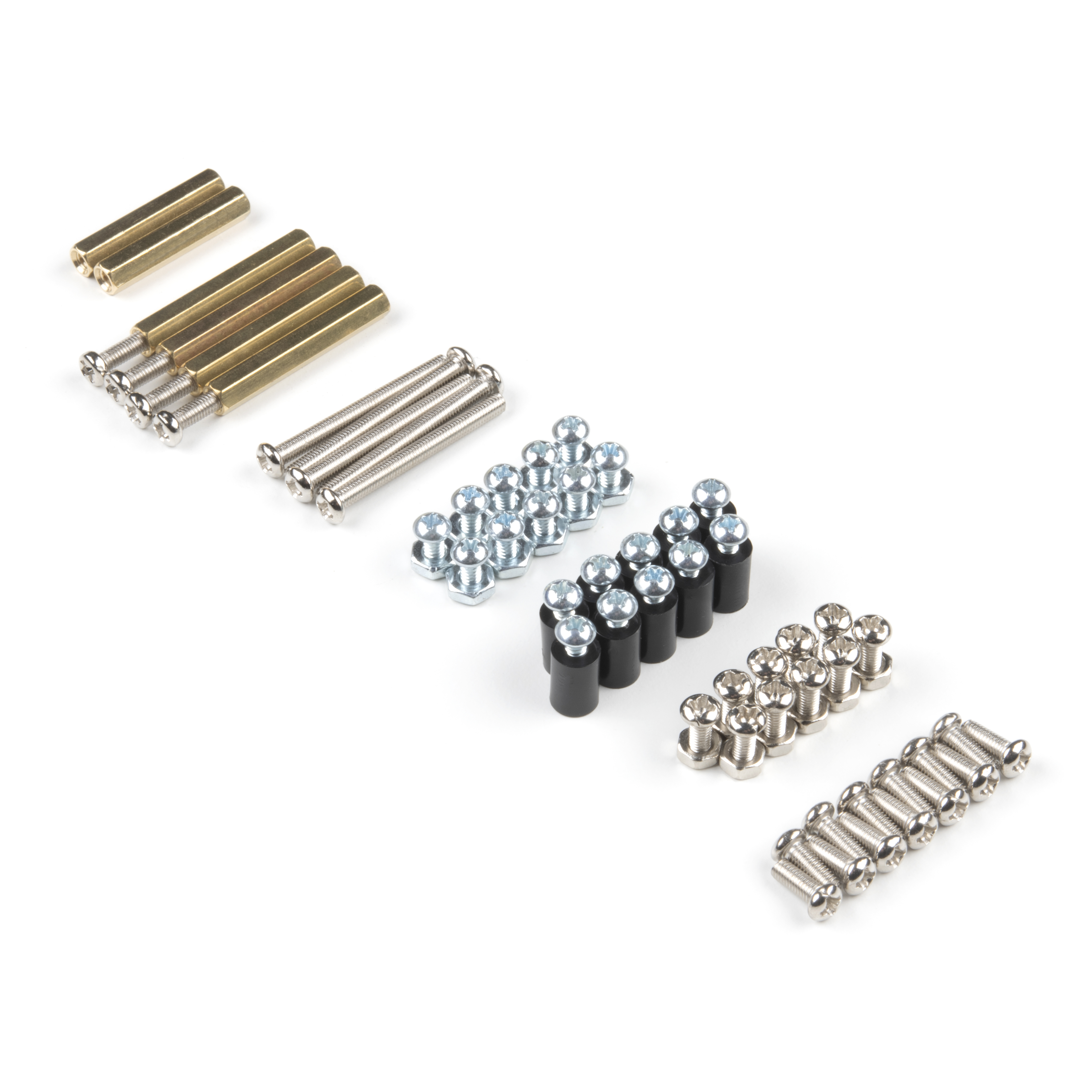
| Part | Qty |
|---|---|
| Standoff - Nylon (4-40; 3/8in.) | 10 |
| 1/4" Phillips Screw with 4-40 Thread | 20 |
| Machine Screw Nut - 4-40 | 10 |
| M2 Nylon hex nut | 4 |
| M2 Nylon screw slotted drive | 4 |
| JetBot Chassis Hardware *included as part of JetBot Chassis Kit | 1 |
Recommended Tools
We did not include any tools in this kit because if you are like us you are looking for an excuse to use the tools you have more than needing new tools to work on your projects. That said, the following tools will be required to assemble your SparkFun JetBot.
- Small phillips & small flat head head screwdriver will be needed for chassis assembly & to tighten the screw terminal connections for each motor. We reccomend the Pocket Screwdriver Set; TOL-12268.
- Pair of scissors will be needed to cut the adhesive Dual Lock Velcro strap to desired size; recommended, but not essential..
- Optional- adjustable wrench or pliers to hold small components (nuts & standoffs) in place while tightening screws; your finger grip is usually enough to hold these in place while tightening screws & helps to ensure nothing is over tightened.
A Note About Directions
When we talk about the "Front," or "Forward" of the JetBot, we are referring to direction the camera is pointed when the JetBot is fully assembled. "Left" and "Right" will be from the perspective of the SparkFun JetBot (i.e. what the JetBot camera sees).
1. Robotics Chassis Kit Initial Assembly
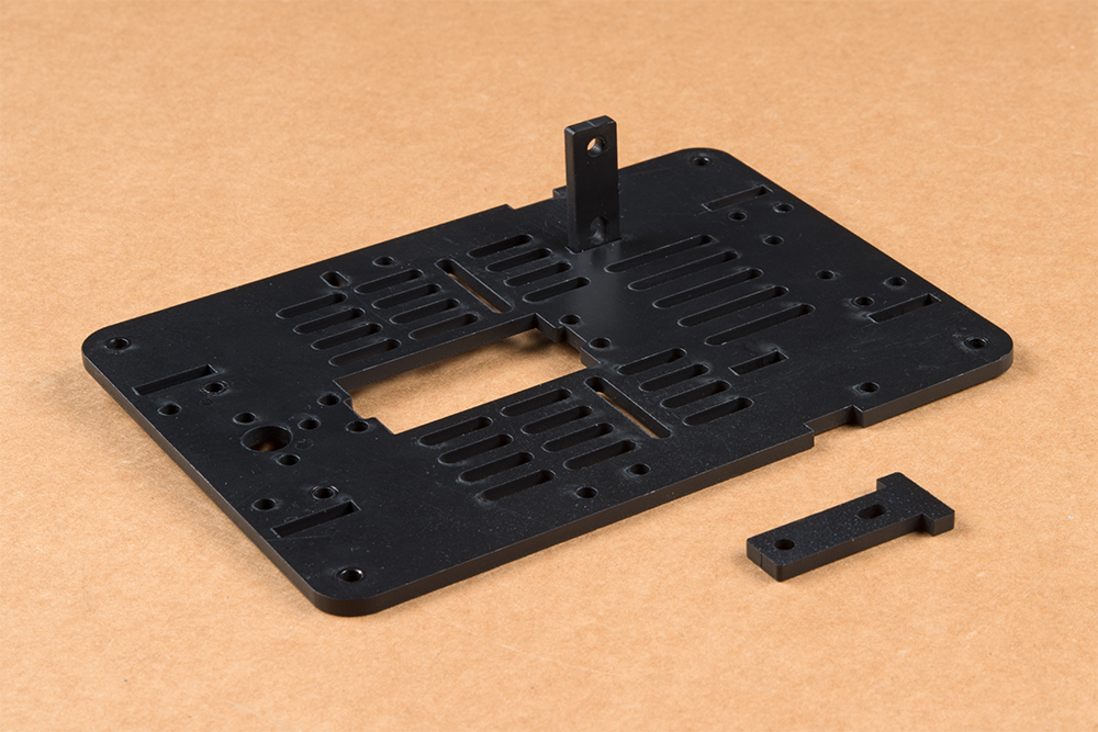
For all SparkFun Jetbot kits, begin with one of the two bare base plates included with the JetBot Chassis Kit. It does not matter which one, they are identical.
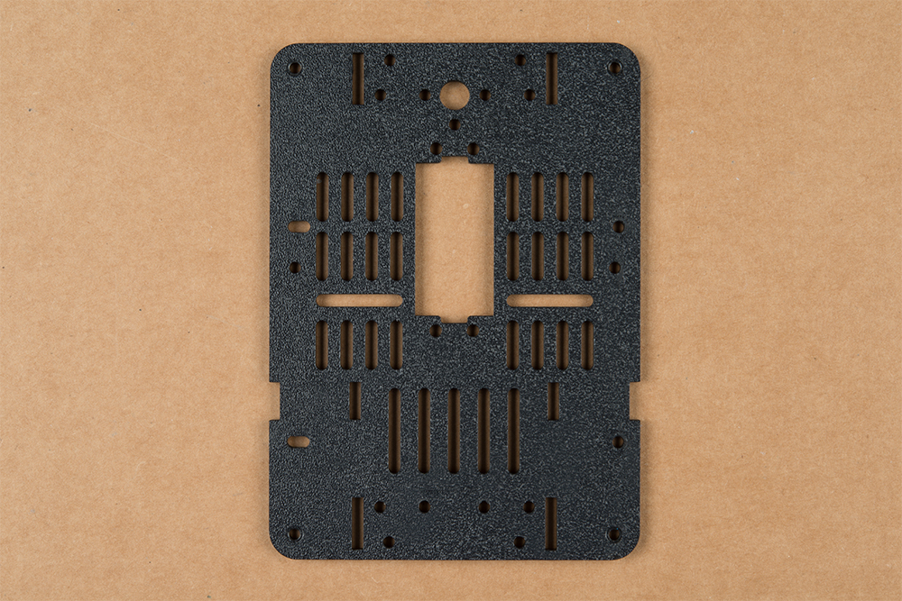
Push two of the included motor mounts through the designated holes in the base plate as shown below. Two more motor mounts will be attached on the outside of the base plate after the motor is installed.
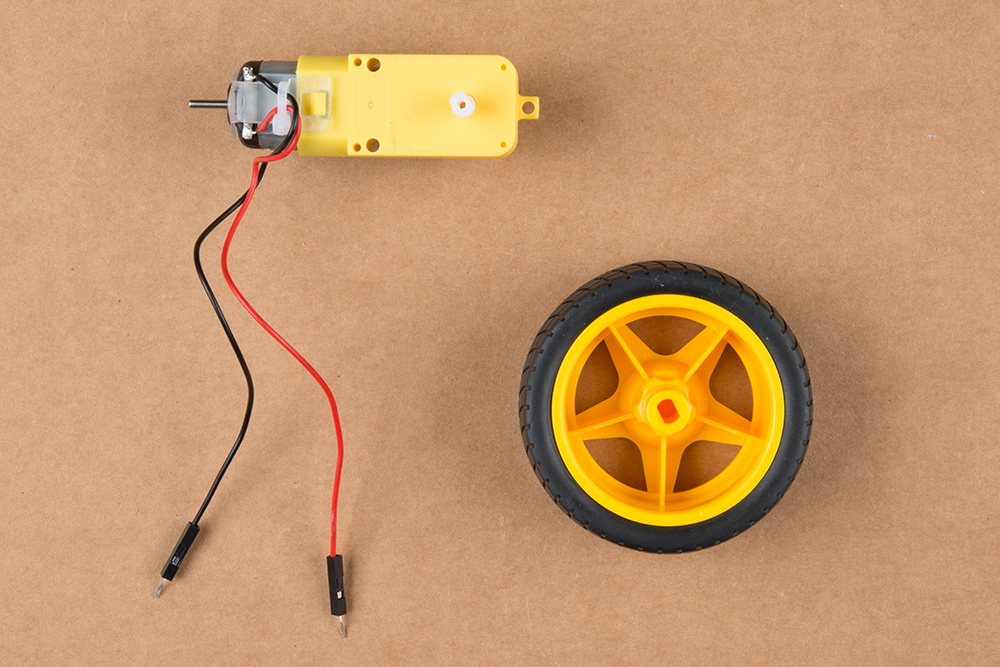
Your JetBot Chassis Kit includes a pair of hobby motors & wheel assemblies.
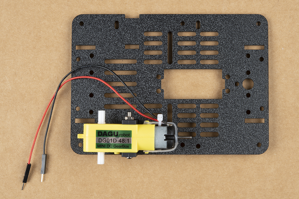
Attach the pair of motors using the long threaded machine screws & nuts included with the JetBot Chassis Kit. The motor will be sandwiched between an internal & external motor mount. Tighten the screws until they are snug.

We prefer the shown orientation below that leaves the extra length of the machine screws & nuts on the inside edge of the JetBot.
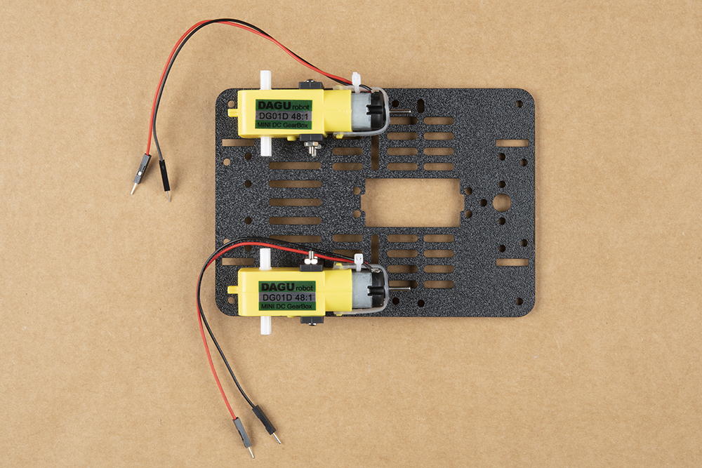
Repeat this process on the other side of the chassis so both motors are symmetric on the base plate.
Once both motors are attached, flip the base plate over as pictured & attach the four longer brass standoffs at each corner of the base plate using the threaded screws included with the JetBot Chassis Kit. These four standoffs are packaged together. Thread one of the machine screws from the JetBot Chassis kit through the base plate & tighten into the brass standoff.
Repeat for each corner.
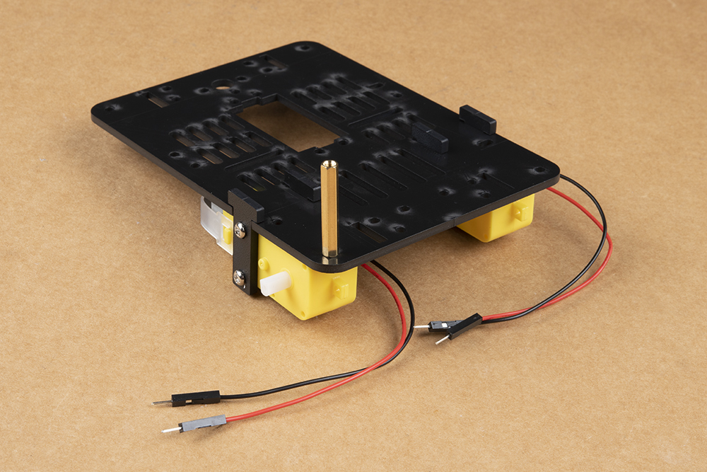
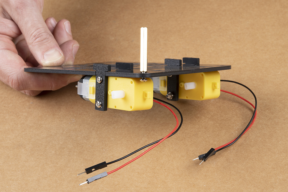
After all standoffs are installed, thread the motor terminal leads through the baseplate as shown. Refer to the photograph of the caster ball assembly to make sure you are using the correctly sized brass standoffs.

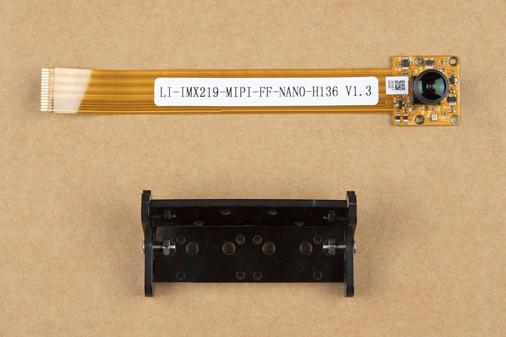
Next, gather the parts needed to assemble the caster ball assembly.
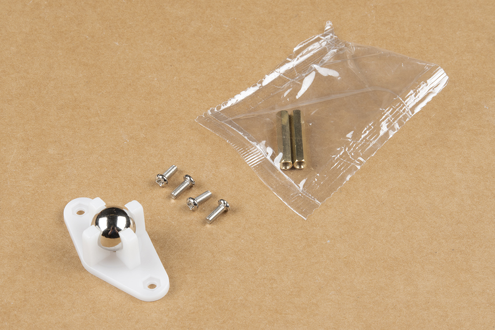
Notice that the brass standoffs used for the caster assembly are slightly shorter than those used for the chassis. The first time you build the SparkFun JetBot, each of these sets of standoffs are packaged together, but it is easy to confuse these once everything has been opened.

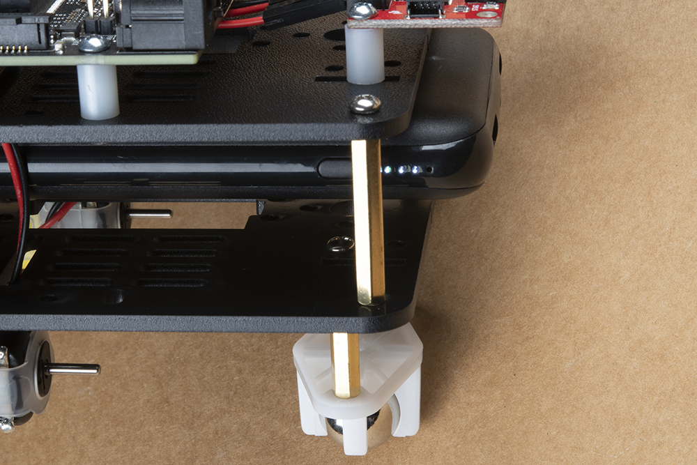
Flip the chassis over and install the shorter brass standoffs as shown in the photo below.

Use the two remaining screws to attach the caster ball casing to the brass standoffs.
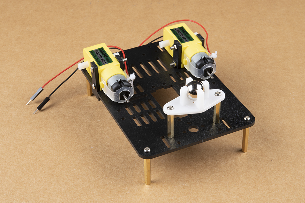
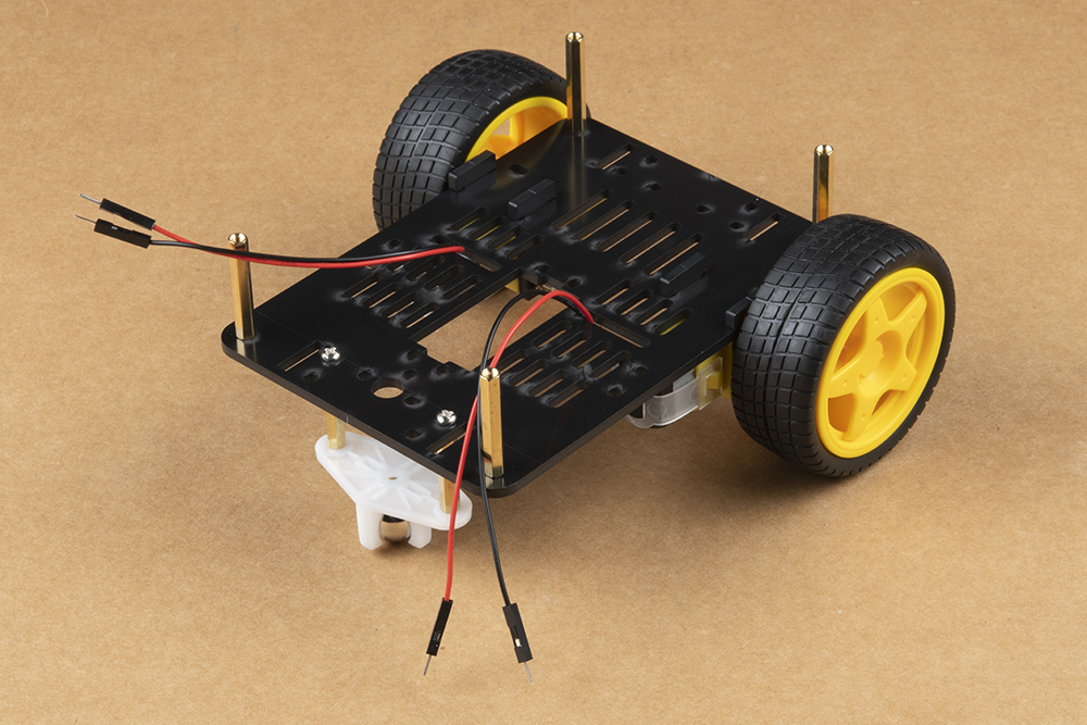
Press the wheels onto the hobby motor axles for a snug friction fit & flip it again Charley! Behold, a very stable three point stance foundation for you to build from.
2. Camera Assembly & Installation
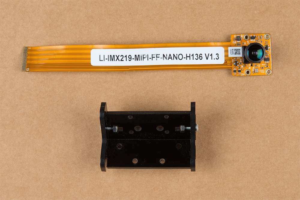
Next, locate the camera mount assembly in the JetBot Chassis Kit. The unassembled view of the parts is laid out in the proper orientation for assembly. The latest revision of the Jetbot Kit includes a camera mount that provides the ability to use stereo vision available on the Jetson Nano Dev Kit V3.
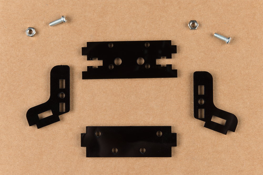

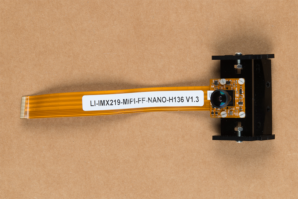
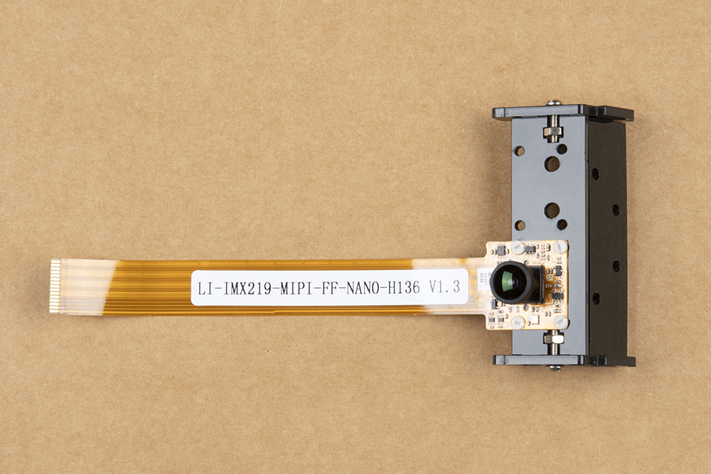
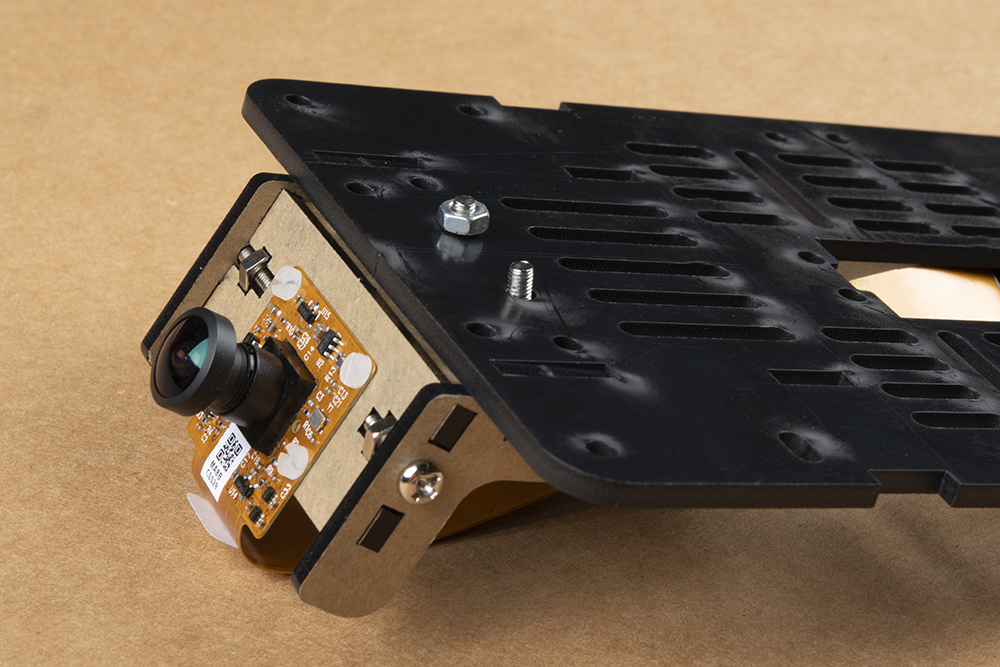
Unpackage the Leopard Imaging camera and assemble the camera mount as shown in the following photograph.
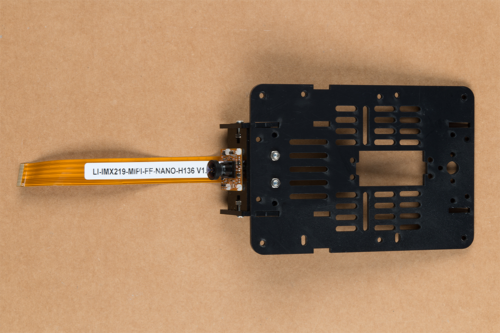
Please reference the note about the "Front" of the JetBot in the end of the Introduction to ensure that you mount the camera on the correct side of the camera mount. Align the four holes in the camera mounting plate with those on the camera. Place all four nylon flathead screws through the camera & camera mounting plate prior to fully tightening the nylon nuts. This will ensure equal alignment across all four screws. While holding the nuts in place with a finger, tighten the screws in a rotating criss cross pattern; similar to how you tighten lug nuts on a car rim.
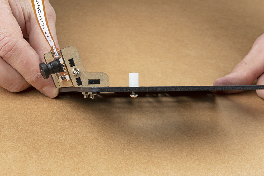
Attach the camera mount & camera to the JetBot Chassis Kit top plate (the unused base plate) using the slightly longer sets of screws and nuts included in the chassis kit (pictured below). Align the plastic tabs on the camera mount to the rectangular cutouts on the front of the chassis top plate. This will result in a sung press fit.
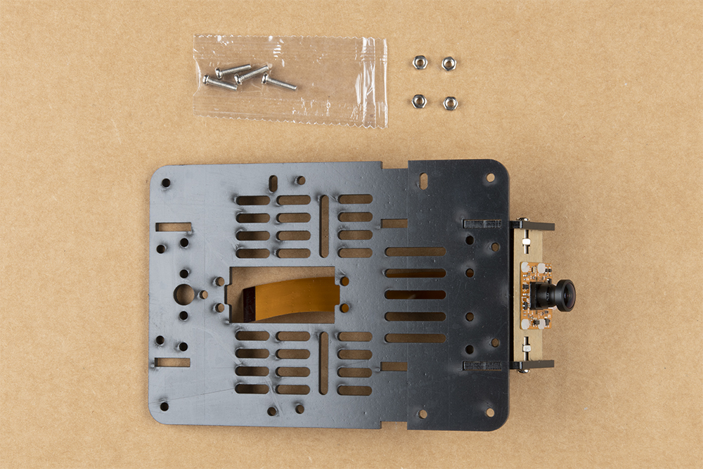
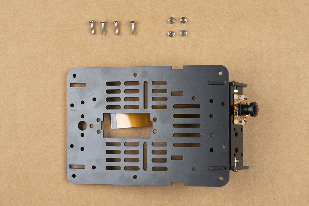
Use the screws to align the holes in the camera assembly with the corresponding holes in the chassis top plate.
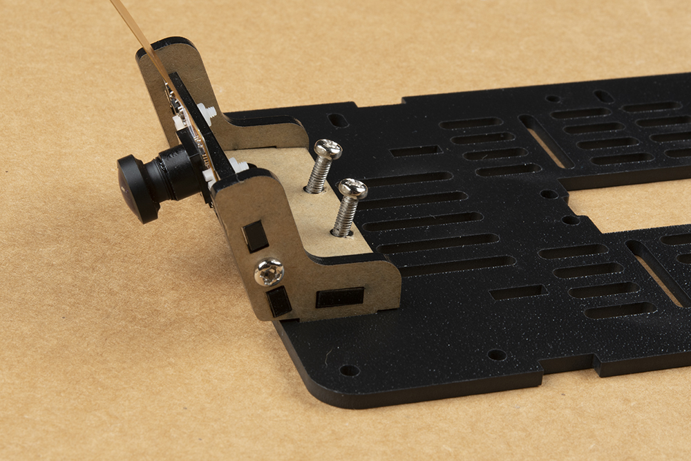
Use your small Phillips head screwdriver to thread the screws through the mounting plates. The chassis kit I got was pretty sung and required me to screw them through.
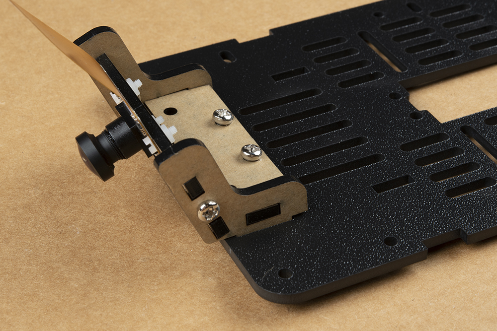
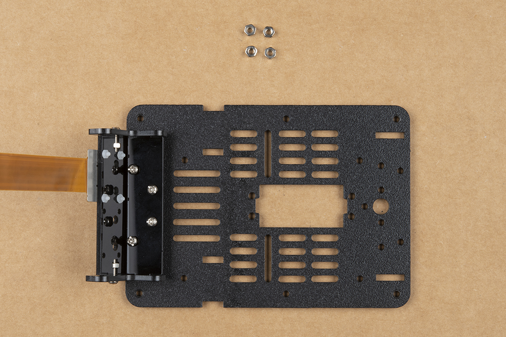
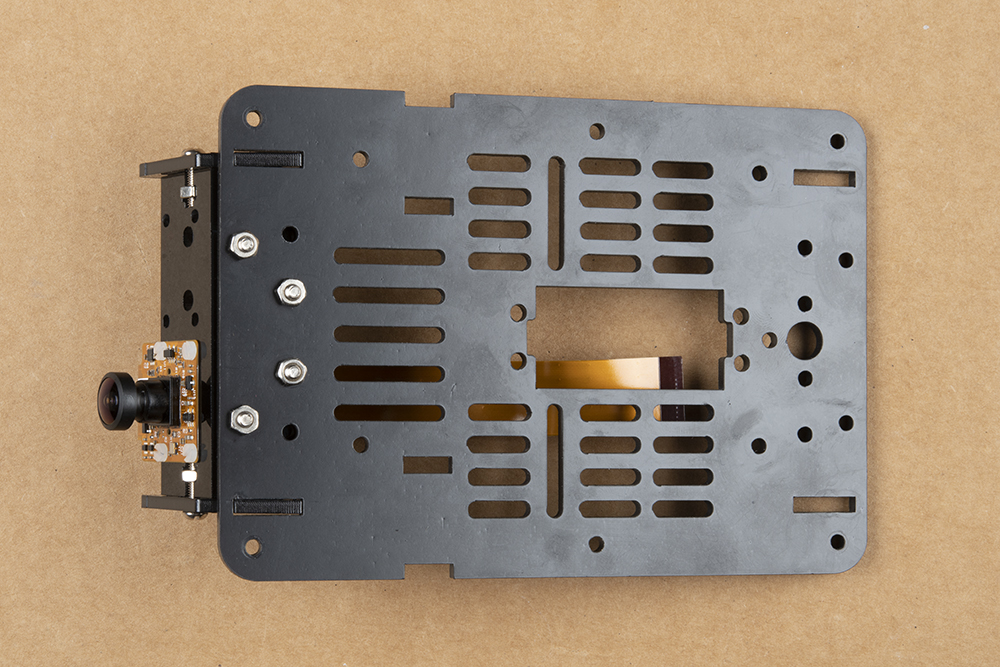
Flip the chassis over & thread two nuts onto the exposed threads of the camera mount hardware.
The final assembly will look something like what is pictured below. We have found that this assembly is attached sufficiently by using 2 of 4 screws, but do whatever feels right.
3. Accessory Installation to Main Chassis
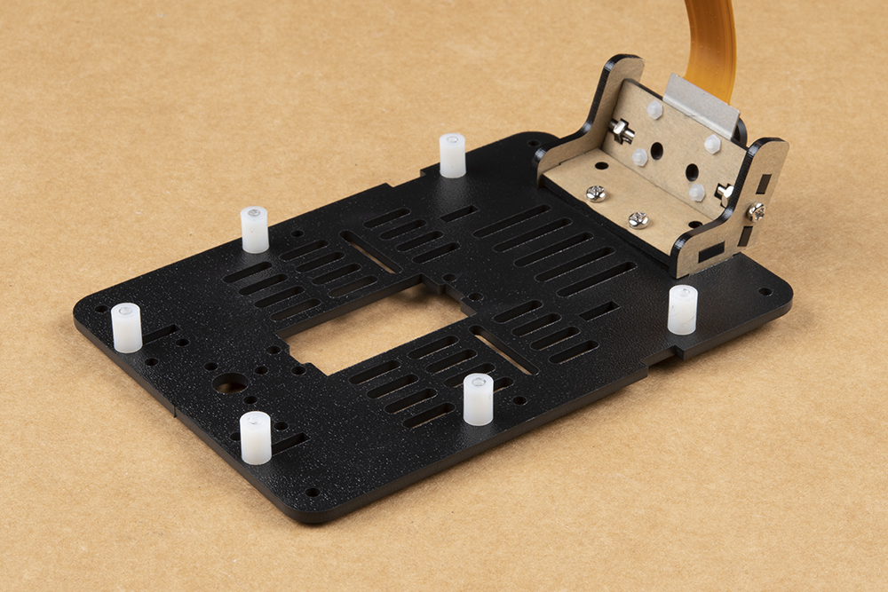
Install the included nylon standoffs using the included 4-40 screws (10 packs) on the top mounting plate (the one we just finished attaching our camera and mount to). Pictured below are the standoffs for the Jetson Nano Dev Kit, the SparkFun Qwiic Motor Driver, and SparkFun Qwiic OLED. Be sure to keep the standoffs on the right side somewhat loose. The mounting holes in the top plate are oblong to compensate for manufacturing tolerances & ensure a secure fit to the Jetson Nano Dev Kit.

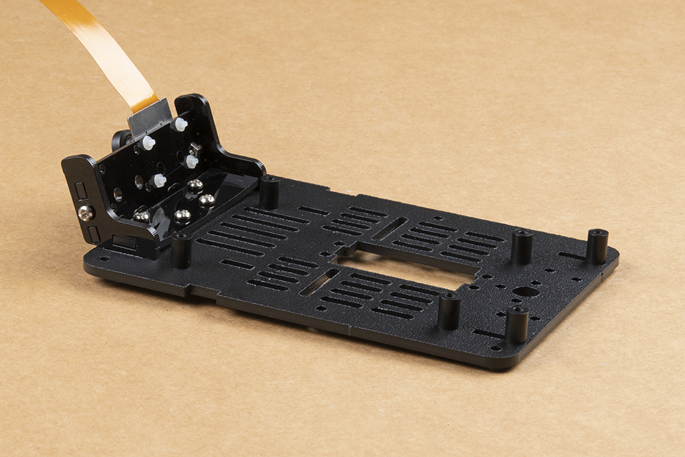
The following instructions for battery installation will be the same for all Jetbot versions.
Cut the strip of dual lock Velcro into two roughly equal sized strips.
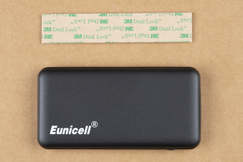
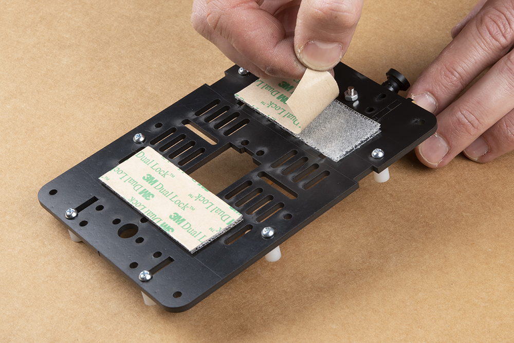
We figured you could handle this, but we already had the camera all set up & scissors in hand... Take one side of the dual lock Velcro and attach to the top of the chassis as shown.

Place the corresponding pieces of dual lock Velcro on the chassis assembly top plate as pictured. Please ensure that all standoffs for the Jetson Nano & Qwiic boards are already installed on the chassis top plate; see photo. Additionally, ensure that the camera mount has been attached to the top plate as well. This will ensure that the battery does not physically hit any mounting screws.

Remove the protective film from the Dual Lock and try not to touch the sticky part.
Line up the battery pack as shown to ensure correct orientation of the USB ports & no interference between the battery pack and mounting hardware.
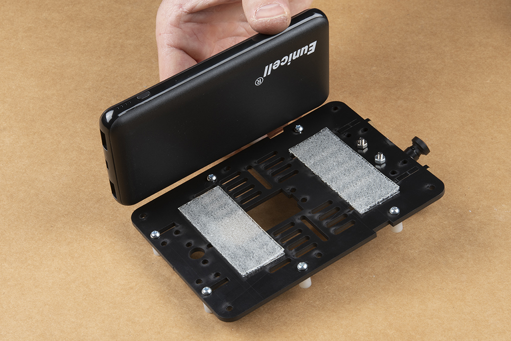
This photo shows how to place the battery pack to not touch the camera mount hardware while not extending too far out the back of the SparkFun JetBot.
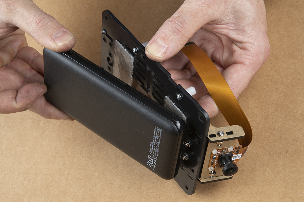
Press firmly on the battery pack to attach the dual lock Velcro interface between the chassis and battery.
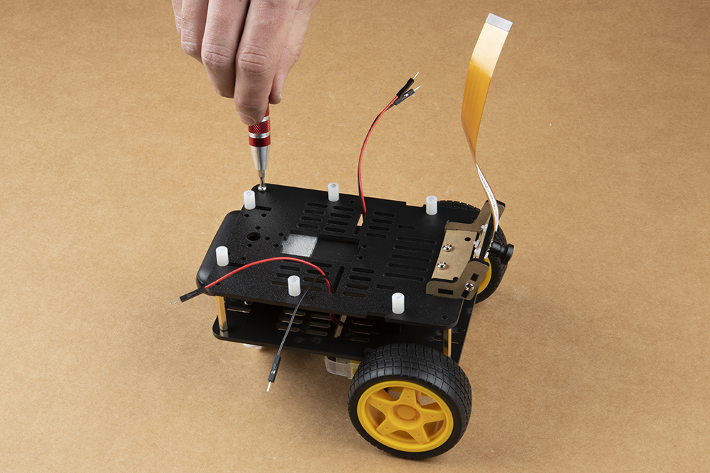
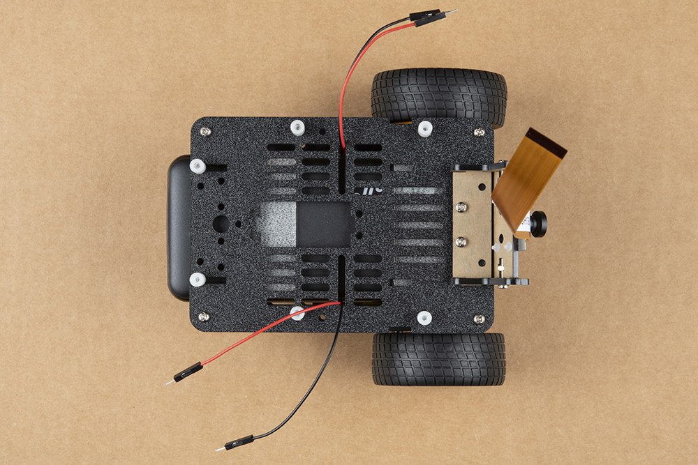
Route one set of motor leads at a time through the chassis top plate as shown.
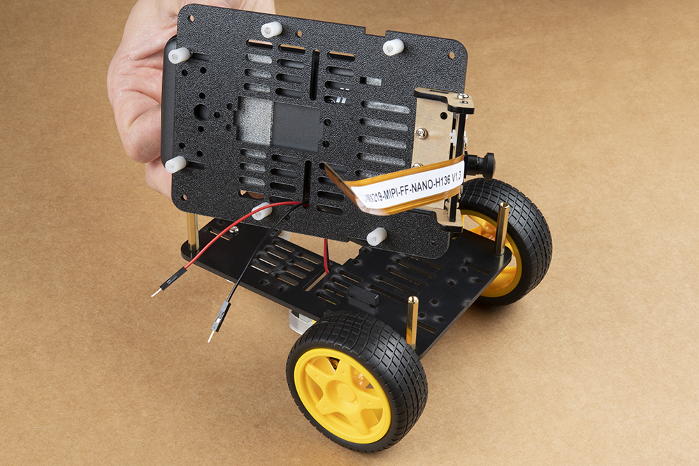
Attach the top plate to the base plate brass standoffs using the four remaining screws from the JetBot chassis kit.
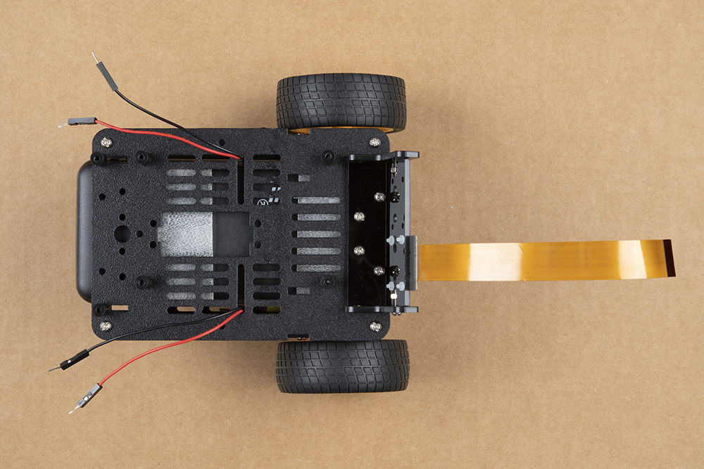
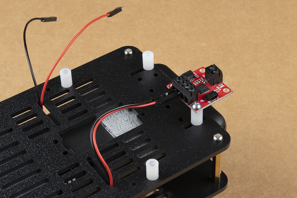
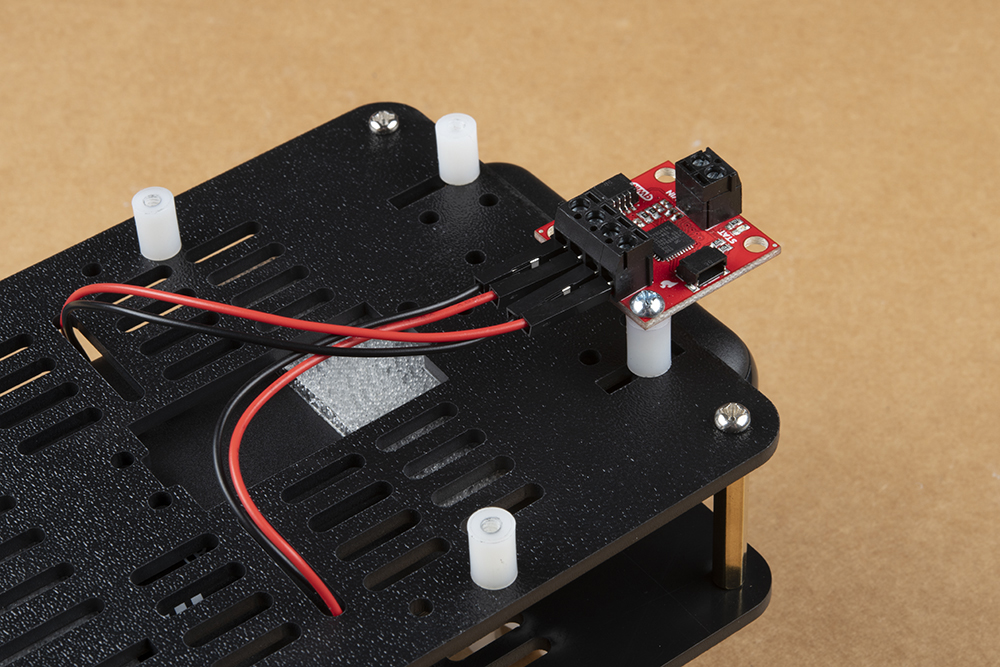
Once the chassis is fully assembled, attach the SparkFun Qwiic Motor Driver as shown using the mounting hole on the board to the right of the 4x motor screw terminal. Attach the motor leads as pictured; see below for more details.
Connect the motor leads according to the table below; remember the "Right" & "Left" designations from the Introduction. They should match the image above. The right motor is on the right side of this photo.
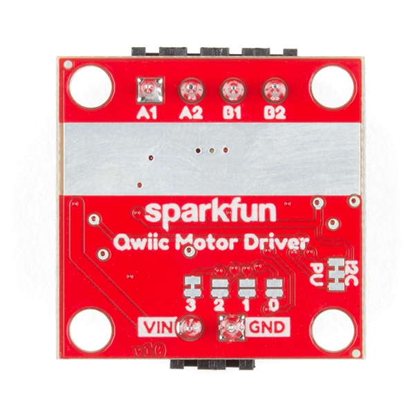
| A1 | A2 | B1 | B2 |
|---|---|---|---|
| Left Motor Ground (-) | Left Motor Power (+) | Right Motor Ground (-) | Right Motor Power (+) |
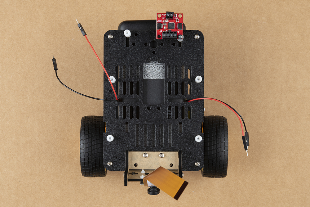
Shown below: Left motor hookup to Qwiic Motor Driver screw terminals.
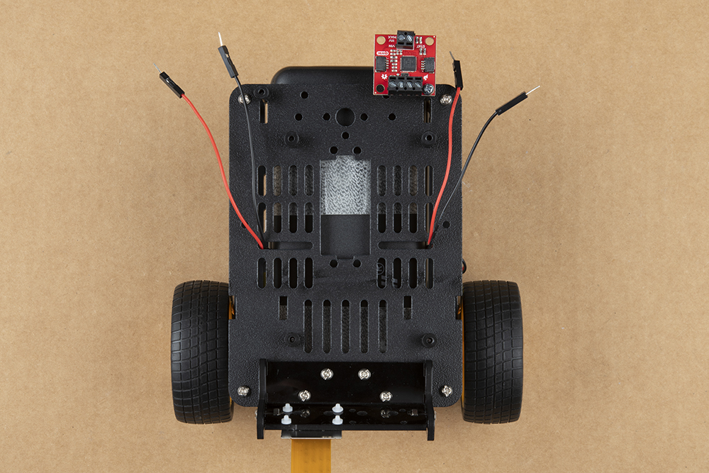
Shown below: Right motor hookup to Qwiic Motor Driver screw terminals.
Install the Edimax USB WiFi & Bluetooth Adapter into one of the USB ports on the Jetson Dev Kit.
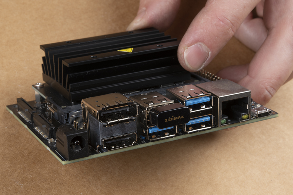
For the Jetson Nano 2GB a WiFi adaptor is included. Install the adaptor into one of the USB ports.
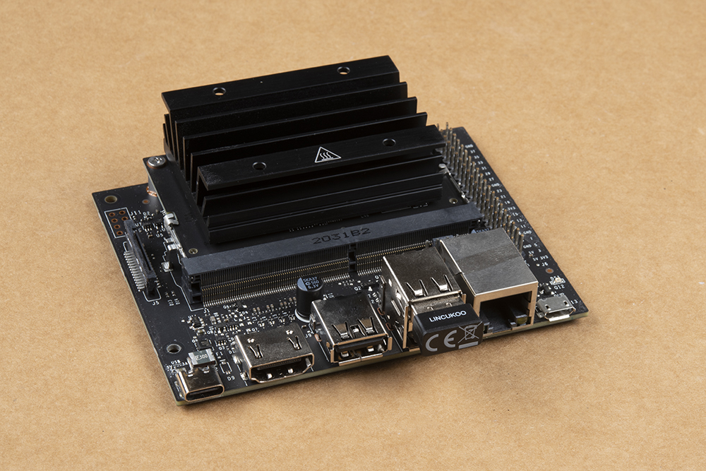
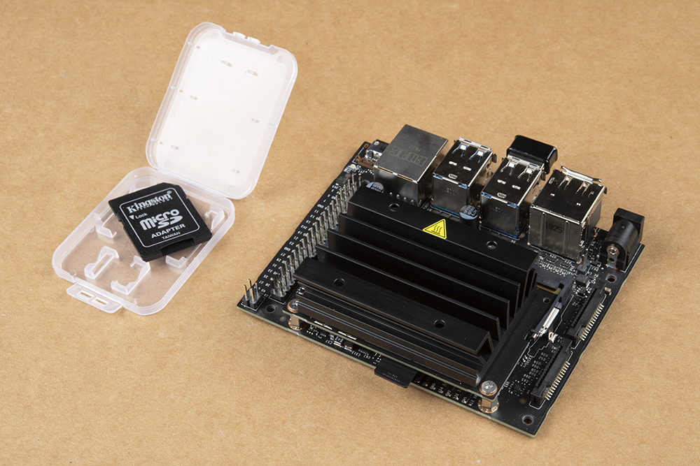
Remove the MicroSD card with the SparkFun JetBot Image (pre-flashed) from the included case & adapter and place it into the MicroSD card slot on the Jetson Nano module. It is easier to do this prior to installing the Jetson Nano Dev Kit onto the chassis and with the Dev Kit upside down as pictured, but you do you.

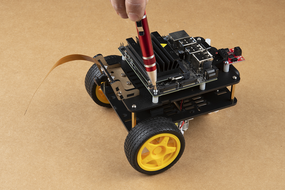
Attach the Jetson Nano Dev Kit using four 4-40 screws to the previously installed Nylon standoffs. Remember we left the right side standoffs loose so align them with the mounting holes on the Jetson Nano Dev Kit & tighten until sung.

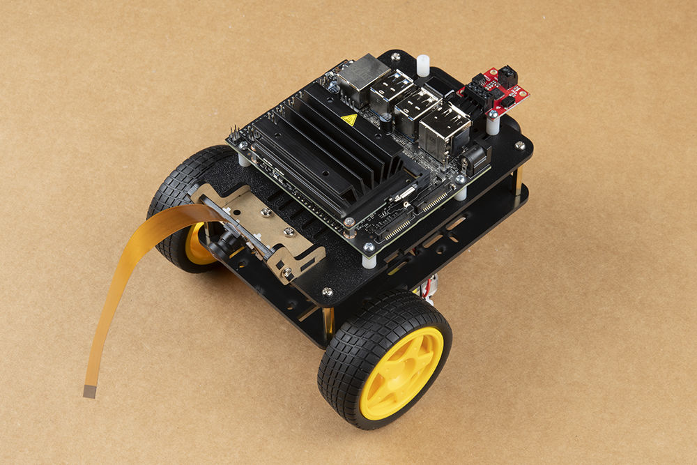
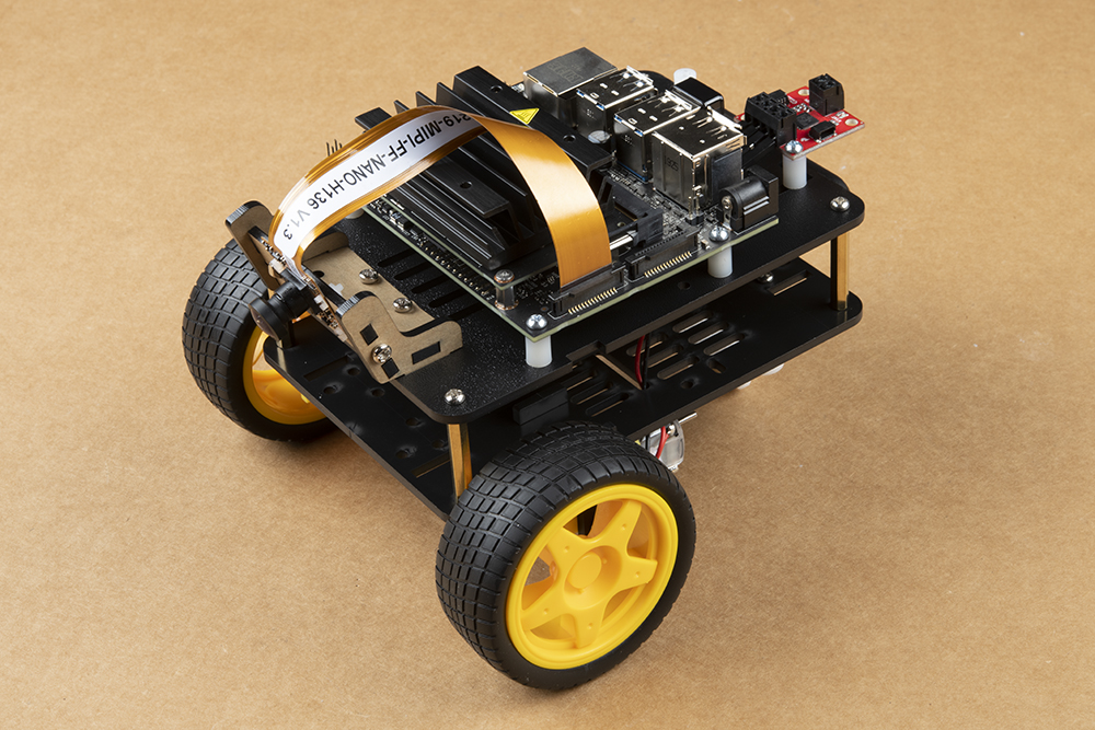
Attach the Leopard imaging camera ribbon cable as shown to the Jetson Dev Kit. This half helix ensures the contacts on the ribbon cable attach to the contact on the Jetson Dev Kit camera connector.

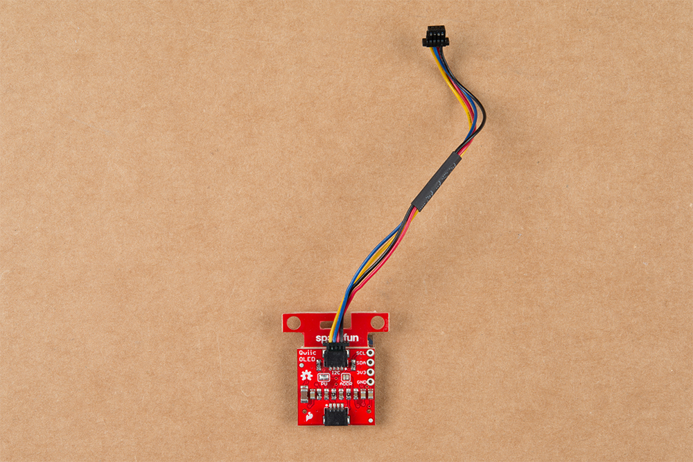
Attach the 100mm Qwiic cable to the underside of the SparkFun Qwiic Micro OLED as shown below.
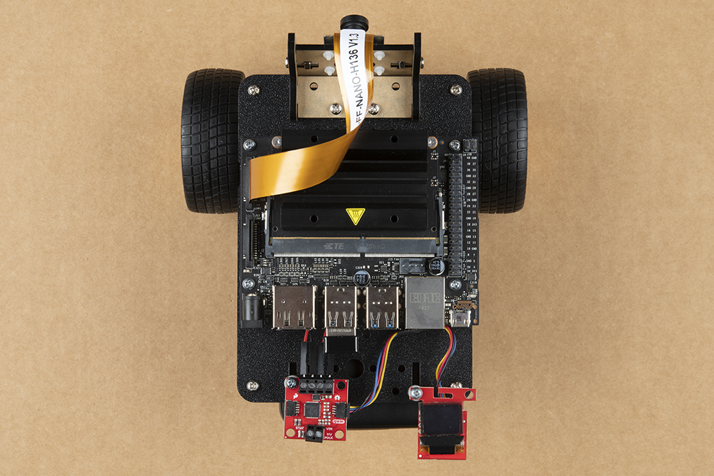
Attach the SparkFun Qwiic Micro OLED to the JetBot Chassis using another Nylon Standoff & 4-40 screw. Attach the 100mm Qwiic cable to the SparkFun Qwiic Motor Driver. Secure the Qwiic Micro OLED by tightening the screw until sung.
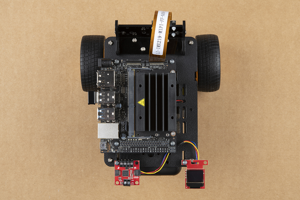
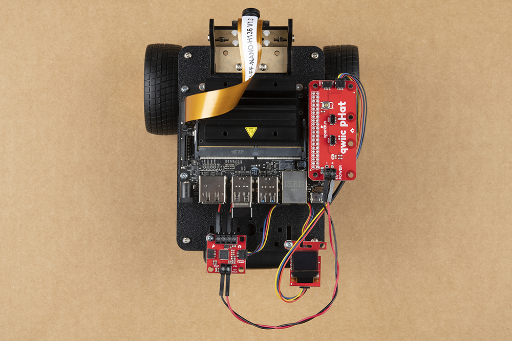
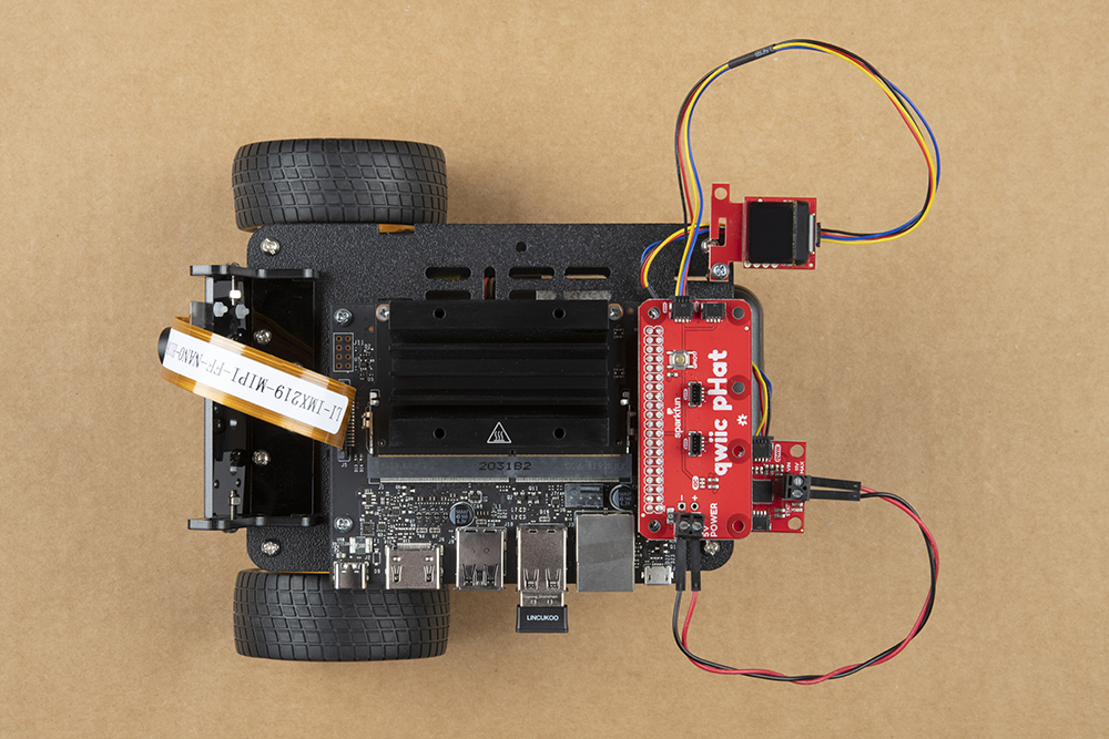
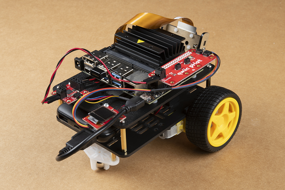
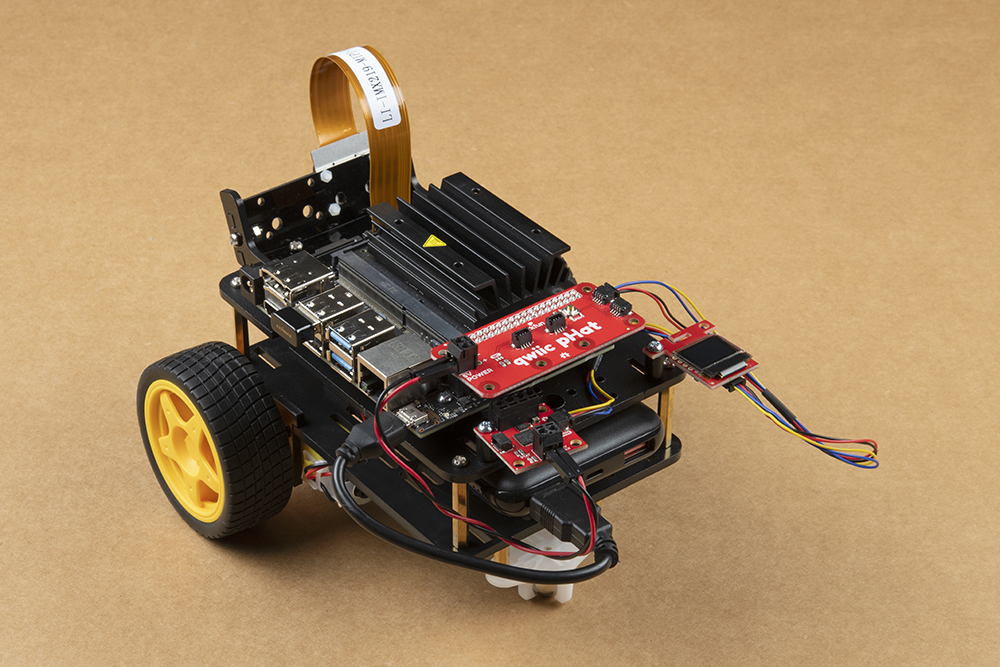
Connect the qwiic pHAT on the Jetson Nano Dev Kit's 2x20 GPIO header taking care to align it as the photo below shows. Additionally, connect the SparkFun Qwiic Micro OLED display to the Qwiic pHAT using the 200mm Qwiic cable.

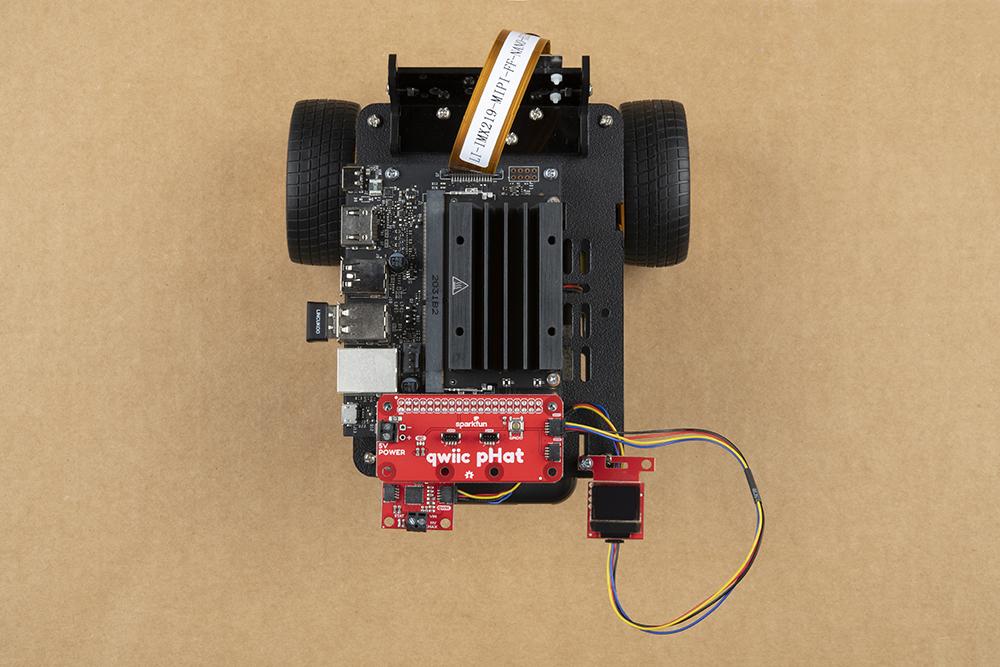
Finally attach the Qwiic Motor Driver's motor power screw terminals to the 2 pin screw terminal for 5V and Ground on the Qwiic pHAT using the included 6 inch M/M jumper wires. We recommend using one black wire (ground) & one red wire (power), but you can use any included color your head desires.
Check the battery power on the USB pack by pressing the power button on the side of the battery. Four dots means it is fully charged. The Jetson is fairly power hungry. We recommend only powering up your SparkFun JetBot with a fully charged battery pack.
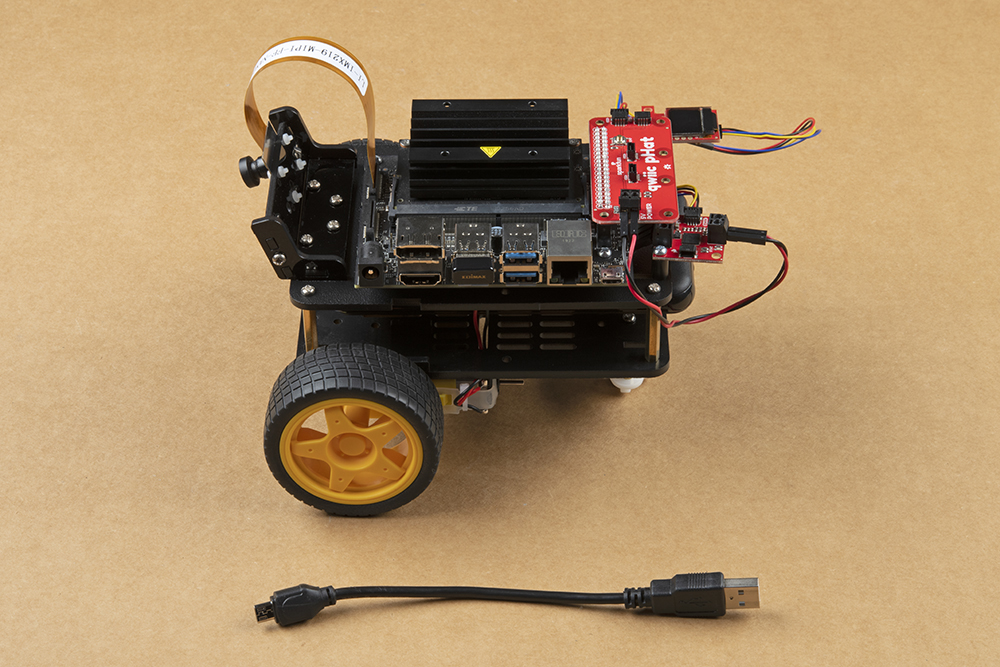
Use the included 6 inch USB Micro-B Cable to connect the Jetson Nano Dev Kit to the battery pack.

Note: Make sure the USB cable is plugged into the orange USB port (shown closest to the USB cable in the above photo) on the battery pack. This will provide the required 3.1A @ 5V required by the Jetson Nano Dev Kit.
In the new revision of the battery pack, both USB ports on the battery pack are orange. We recommend using the USB port that is on the opposite side of the power button. Otherwise, we have found that the other USB port can cause the Jetson Nano Dev kit to brown out during its boot sequence.
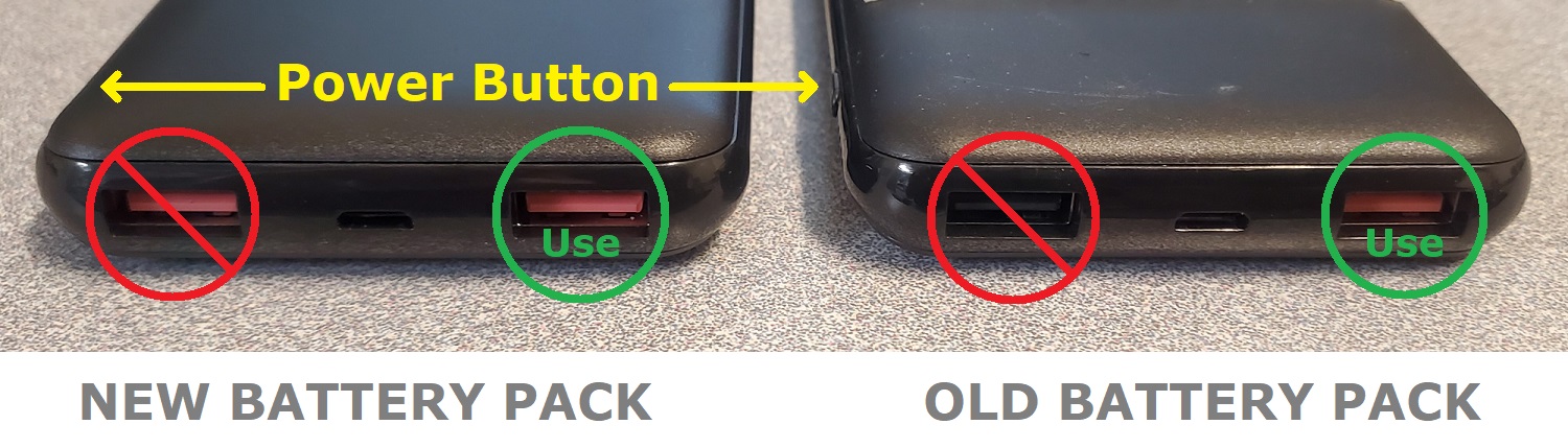
USB ports on the battery pack. (Click to enlarge)

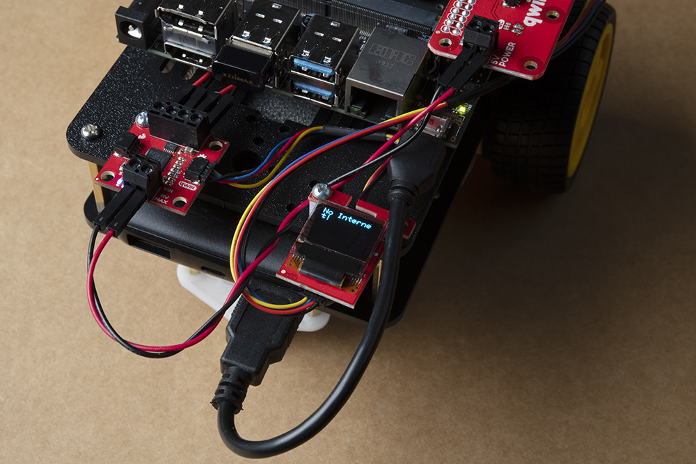
If the Jetson Nano does not power on once your USB cable is connected, press the power button the battery pack to turn the JetBot on. Allow the JetBot a few minutes to power up. When the JetBot is ready, the Micro OLED will display the SparkFun flame logo followed by the available disk image space & IP address once connected to a WiFi network; see example photos below.


Congratulations! Your SparkFun JetBot is now fully assembled!
4. Software Setup Guide from NVIDIA
Attention: The SD card in this kit comes pre-flashed to work with our hardware and has the all the modules installed (including the sample machine learning models needed for the collision avoidance and object following examples). The only software procedures needed to get your JetBot running are steps 2-4 from the Nvidia instructions (i.e. setup the WiFi connection and then connect to the JetBot using a browser). Please DO NOT format or flash a new image on the SD card; otherwise, you will need to flash our image back onto the card (instructions below).
Your SparkFun JetBot comes with a Pre-Flashed micro SD card. Users only need to plug in the SD card and set up the WiFi connection to get started.
- The default password on everything (i.e. login/user, jupyter notebook, and superuser) is "jetbot".
- We recommend that users change their passwords after initial setup. These are typically covered on the first boot of your Jetson Nano as detailed in the NVIDIA Getting Started with Jetson Nano walkthrough
Software Setup
The only step needed to get your JetBot kit up and running is to log into the JetBot and setup your WiFi connection. Once that is done, you are now ready to connect to the JetBot wirelessly. If you need instructions for doing so, you can use the link below.
Instructions
- Skip step 1 of Nvidia's instructions: It references how to flash your SD card, so feel free to skip to Step 2 - Boot Jetson Nano.
- Skip step 5 of Nvidia's instructions: This step should already be setup on the pre-flashed SD card.
- If in the future, you need to update your notebooks, you can follow Step 5 - Install latest software (optional) to download the repository (don't download it into the home directory and skip the last command line instruction of the forth step).
Get and install the latest JetBot repository from GitHub by entering the following commands
git clone https://github.com/NVIDIA-AI-IOT/jetbot
cd jetbot
sudo python3 setup.py install
sudo python3 setup.py install in the command line will overwrite the software modifications for SparkFun's hardware in the kit.Troubleshooting
In the event that you accidentally missed the instructions above, here are instructions to get back on track.
Re-Flashing the SD card
If you need to re-flash your SD card, follow the instructions from Step 1 Nvidia's guide. Alternatively, to download and use our image instead (click link below). Please note the model of your microSD card with regard to which version you need to download.
Note: Balena Etcher software (NVIDIA's recommendation) internally takes care of un-zipping disk image files. If you are using another program Don't forget to uncompress (i.e. unzip, extract, or expand) the file from the .zip file/folder first if needed. You should be pointing the "flashing" software to a ~62GB .img file to flash the image (sparkfun_jetbot_v01-xx.img) onto the SD card.
Not every unzip utility can handle this large of a file! The Windows 10 'Extract All' command has been found to work as well as 7Zip and Winzip.
Image Compatibility
- Not compatible with the 2GB Nano Kit
- v01-11 Image: Won’t fit on older non-CANVAS SD cards
- v01-00 Image: Not compatible with the newer Jetson Nano boards
- v2.1 Kit (Nano's with two camera connectors)
Alternatively, there are other options for flashing images onto an SD card. If you have a preferred method, feel free to use the option you are most comfortable with.
Re-Applying the Software Modifications
If you have accidentally overwritten the software modifications for the hardware included in your kit, you will need to repeat Step 5 from Nvidia's guide from the desktop interface (if you are comfortable performing the following steps from the command line, feel free to do so).
Skip steps 1 and 2: Plug in a keyboard, mouse, and monitor. Then log in to the desktop interface (if you haven't changed your password, the default password is: jetbot).
Follow step 3: Launch the terminal. There is an icon on sidebar on the left hand side. Otherwise, you can use the keyboard short cut (Ctrl + Alt + T).
Follow step 4: However, before you execute sudo python3 setup.py install you will want to copy in our file modifications to the jetbot directory you are in.
- Begin by downloading our files (click link below).
Next, extract the file.
Next, replace the files in the
jetbotfolder. The file paths must be the same, so make sure to overwrite files exactly.
Click on the icon that looks like a filing cabinet on the left hand side of the GUI. This is your Home directory. From here, you will need to proceed into the jetbot folder. There you will find a jetbot folder with similar files to the ones you just extracted. Delete the folder and copy in our files (you can also just overwrite the files as well).
- Now, you can execute
sudo python3 setup.py installin the terminal.
Follow step 5: Finish up by following step 5. Now you are back on track to getting your JetBot running again!
Note: If you need to install the Python packages for the Qwiic devices (i.e. the OLED and SCMD motor driver), use the following command in the terminal: sudo pip3 install sparkfun-qwiic.
5. Examples
The "object following" Jupyter Notebook example won't work due to the required dependencies that had not been released by NVIDIA prior to the creation of the SparkFun JetBot image. These updates can be manually installed on your Jetson Nano with the
JetPack 4.2.1 release.
Update: The engine generated for the example utilized a previous version of TensorRT and is therefore, not compatible with the latest release. For more details on this issue, check out the following GitHub issue.
Update: One of our customers was able to find an older image that is compatible with the pre-built engine. For more details, check out the following forum post.
Resources and Going Further
Now that you've successfully got your JetBot AI up and running, it's time to incorporate it into your own project!
For more information, check out the resources below:
- Getting Started With Jetson Nano Developer Kit
- Assembly Guide for SparkFun JetBot AI Kit (previous version)
- SparkFun Qwiic Motor Driver Hookup Guide
- SparkFun Qwiic Micro OLED Hookup Guide
- SparkFun Qwiic pHAT Hookup Guide
- JetBot ROS GitHub Repository
- Getting Started with AWS IoT Greengrass
- NVIDIA Jetson Forums
- NVIDIA JetBot GitHub Issues
- NVIDIA JetBot GitHub
- NVIDIA JetBot GitHub Wiki
- NVIDIA JetBot software setup
Need some inspiration for your next project? Check out some of these related tutorials: