AST-CAN485 Hookup Guide
Hardware Overview
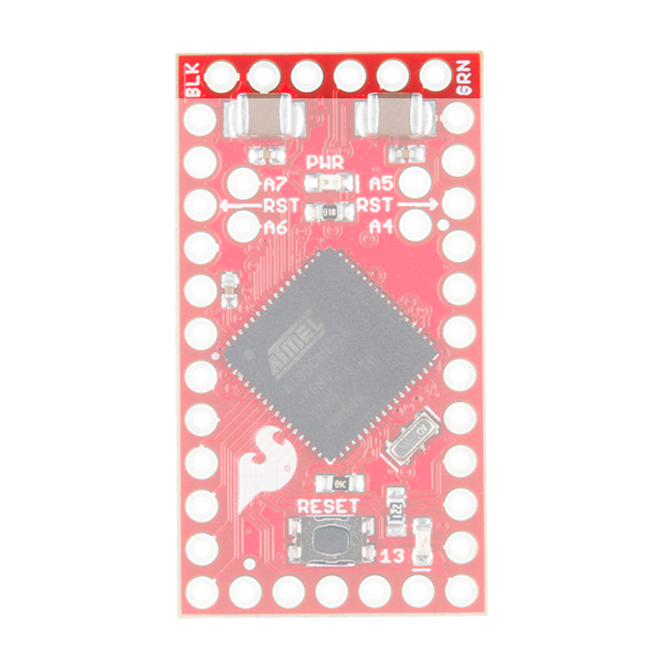
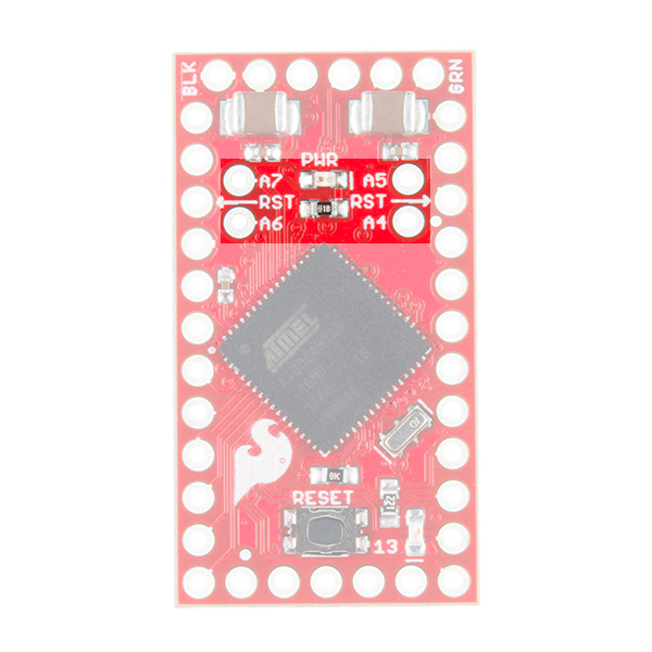
The CAN485 adopts the same tiny form factor as the Pro Mini measuring about 34.65mm x 19.20mm, making it easily embeddable in applications where space is limited. The pin layout is the same as the Arduino Pro Mini. This makes it pin compatible with existing Pro Mini shields and applications. An additional row of pins below the RESET button on the fourth side contains the CAN and RS485 ports.
 |
 |
| AST-CAN485 Dimensions | Arduino Pro Mini Dimensions |
Pinout
While the pin assignments are similar to the Arduino Pro Mini, there are some differences in their functions. Care should be taken when using shields designed for the Pro Mini with the CAN485. The graphical datasheet gives more details about the pins and their functions.

The CAN485 is based on the Atmel AT90CAN128 processor. The processor runs at 16MHz, has 128KB or Flash, 4KB of SRAM and features a hardware CAN controller. The CAN485 breaks out commonly used communications ports and pin functions including: I2C, SPI, UARTs, 8 analog inputs, and 6 interrupt enabled pins.
More information can be found on the AT90CAN128 datasheet and AST-CAN485 schematic.
| Target's External Power | CAN485 | AVR Programmer |
|---|---|---|
| D1 (TX0) on FTDI Header | MISO | |
| D13 (SCK) | SCK | |
| RST | RST | |
| 5V | 5V | 5V |
| D0 (RXI) on FTDI Header | MOSI | |
| GND | GND | GND |
Power
There are several ways that the CAN485 can be powered.

The CAN485 has an on-board regulator allowing for an unregulated input voltage to be supplied on the RAW pin. The allowable input voltage range is 7-16V, however 7-12V is recommended.
A regulated 5V supply may also be supplied directly to Vcc. Supplied voltage must be in the range 4.5V to 5.5V. Power can also be supplied to the FTDI header by a FTDI breakout.
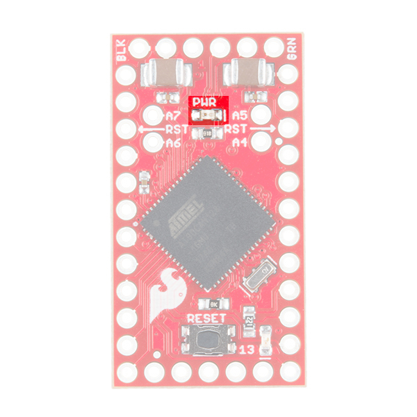
Once the board is powered, the PWR led will light up.
FTDI Programming Header
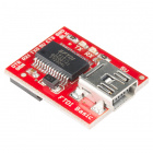
Like the Pro Mini, the CAN485 has no on-board USB connection. An external FTDI breakout board is required to program the board or connect it to a PC.
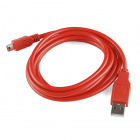
To connect, you would need a 5V FTDI, header pins to connect, and a mini-B USB cable.

CAN Port
The CAN controller is hardware accelerated, allowing for high speed CAN communication with minimal processor overhead. The on-board CAN transceiver means the CAN485 can be directly connected to a CAN network with no additional electronics.
 |
 |
| AST-CAN485 Front Side: CAN Port | AST-CAN485 Front Side: CAN IC and Port |
Connecting to a CAN Network
The image below shows a typical connection between the CAN485 and a CAN network. The network consists of two lines (CANH and CANL). Multiple devices may be connected in parallel on these lines. The bus must be terminated at each end with termination resistor (typically 100Ω to 120Ω).

For more information, check out the Introduction to CAN Bus.
RS485 Port
Similar to the CAN port, the CAN485 features an on-board RS485 transceiver which allows for simple connection to any RS485 network. While UART1 is consumed by the RS485 port, it is also broken out on pins 22 and 23 if the user would rather use it as a serial port.
 |
 |
| AST-CAN485 Front Side: RS485 Port | AST-CAN485 Back Side: RS485 IC and Port |
Connecting to a RS485 network
The image below shows a typical connection between the CAN485 and a RS485 network. The network consists of two lines (A and B), devices are connected in parallel on these lines. The bus must be terminated at each end with a termination resistor (typically 100Ω to 120Ω)
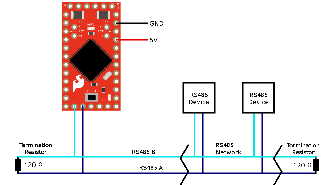
For more information, check out the Introduction to RS485.
JTAG
The JTAG programming and debugging interface is broken out on pins 18-21. This allows for more advanced debugging with Atmel Studio users.
One important implication is that in order to use these pins for I/O, the JTAG interface must be disabled. This can be done by adding a small bit of code to the setup() function.
Software Serial w/ AltSoftSerial
Unfortunately, the AT90CAN128 chip's pins do not support change interrupts. Therefore, the Arduino SoftwareSerial library is not supported. The AltSoftSerial library may be used as an alternative.
There are some limitations associated with the AltSoftSerial library. It uses a Timer resource on the microprocessor. Only one Timer is available so only one AltSoftSerial port is available and it is fixed on pins 5 and 9. AST modified the standard AltSoftSerial library to support the CAN485. The library is available on AST's GitHub.