Favorited
Favorite
14
Hardware Hookup - Initial
Heads up! If you are using a Qwiic cable to power/control your SerLCD, then it is not necessary to solder in any headers or do any logic level conversion. Simply jump ahead to the
I2C Hardware Hookup and Example Code to get up and running quickly.
Install Headers
For this tutorial, we are going to try out Serial UART, I2C, and SPI. In order to easily follow along using a breadboard, solder some headers to the connection ports along the side of your screen. Also, solder some headers onto either side of the logic level converter. This will allow us to easily plug these into the breadboard and wire each data line up with jumper wires.
 |
 |
| Headers on screen |
Headers on logic level converter |
Note, we are going to use the 16x2 model with RGB backlight during this tutorial. If you are using a different model (RGB text or the 20x4), then the header pin-out and spacing is identical.
Connecting to an Arduino
Warning! Do not use the TX pin from your Arduino (aka "hardware serial TX") to control your LCD.
The TX pin is used for Serial Uploads of new sketches onto your Arduino, and will cause problems for both your Arduino and the LCD. In other words, when you upload new code to your "project" Arduino, it will be confused because the screen is sharing that TX pin. Please only use software serial to control your LCD. For all of the Serial UART examples, we have setup software serial on D7.
Warning! The RX input should be a TTL-level signal of 3.3V. If you are using a 5V Arduino, you will need a logic level converter between the two.
In stock
BOB-12009
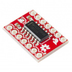
The SparkFun bi-directional logic level converter is a small device that safely steps down 5V signals to 3.3V AND steps up 3.…
120
In stock
BOB-11771
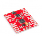
This is a breakout board for the Texas Instruments TXB0104 module. The TXB0104 is a 4-bit bidirectional voltage-level transla…
8
In stock
PRT-14765
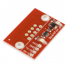
The SparkFun Single Supply Logic Level Converter is logic level and power supply translator in one small package.
Retired
BOB-11955
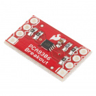
This is a breakout board for the PCA9306 dual bidirectional voltage-level translator. Because different parts sometimes use d…
3
Retired
You should
NOT connect the board directly to RS232-level voltages (which are around +/-10V). This will damage the board. For more information on RS232,
see our explanation here). If you do wish to connect this display to RS232 signals, you can use a level-shifting board to translate the RS232 signals to TTL-level signals.
In stock
BOB-11189
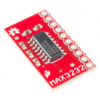
The 'must have' IC for TTL/CMOS projects finally has its own breakout board! This RS232 IC is capable of running at 3V and co…
34
In stock
PRT-00449
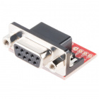
The smallest and easiest to use serial conversion circuit on the market! This board has one purpose in life - to convert RS23…
16
In stock
PRT-08780
The smallest and easiest to use serial conversion circuit on the market! This board has one purpose in life - to convert RS23…
10
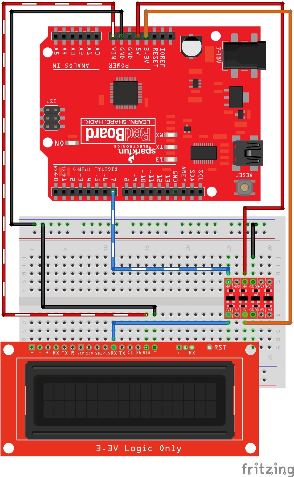
For the first set of examples in this tutorial (SERIAL UART), there are three connections you need to make to the LCD: RX, GND, and RAW. For the other communication protocols that we will explore later, you will need to wire up some other lines. Please see the following Fritzing graphic to see how to wire up your connections through a logic level converter.
 QCPete