AzureWave Thing Plus (AW-CU488) Hookup Guide
 QCPete
 bboyho
Introduction
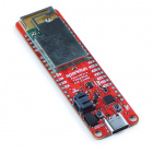
The SparkFun AzureWave Thing Plus is a Feather form-factor development board equipped with the AW-CU488. The module features the Realtek RTL8721DM integrated single-chip low power dual band (2.4GHz and 5GHz) wireless LAN . It also consists of a dual processor core: Real-M300 CPU (Armv8-M, Cortex-M33) and Real-M200 CPU (Armv8-M, Cortex-M23). Connect the SparkFun AzureWave Thing Plus to the cloud to grab current weather conditions in your area, post sensor data to a server, control the lights in your next home automation project, or even calculate the Fast Fourier Transform (FFT) of an input audio signal!

Required Materials
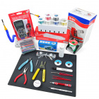
To follow along with this tutorial, you will need the following materials at a minimum. You may not need everything though depending on what you have. Add it to your cart, read through the guide, and adjust the cart as necessary.

Tools
You will need a soldering iron, solder, and general soldering accessories for a secure connection when using the plated through holes.


Prototyping Accessories
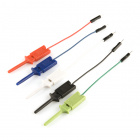
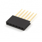
Depending on your setup, you may want to use IC hooks for a temporary connection. However, you will want to solder header pins to connect devices to the plated through holes for a secure connection. For those using the stackable headers, you will want to cut or pull a pin from the 6-pin header to connect to the rows of 1x5 pins on the AzureWave Thing Plus.


Qwiic Cables
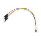
For those that want to take advantage of the Qwiic enabled devices, you'll want to grab a Qwiic cable.


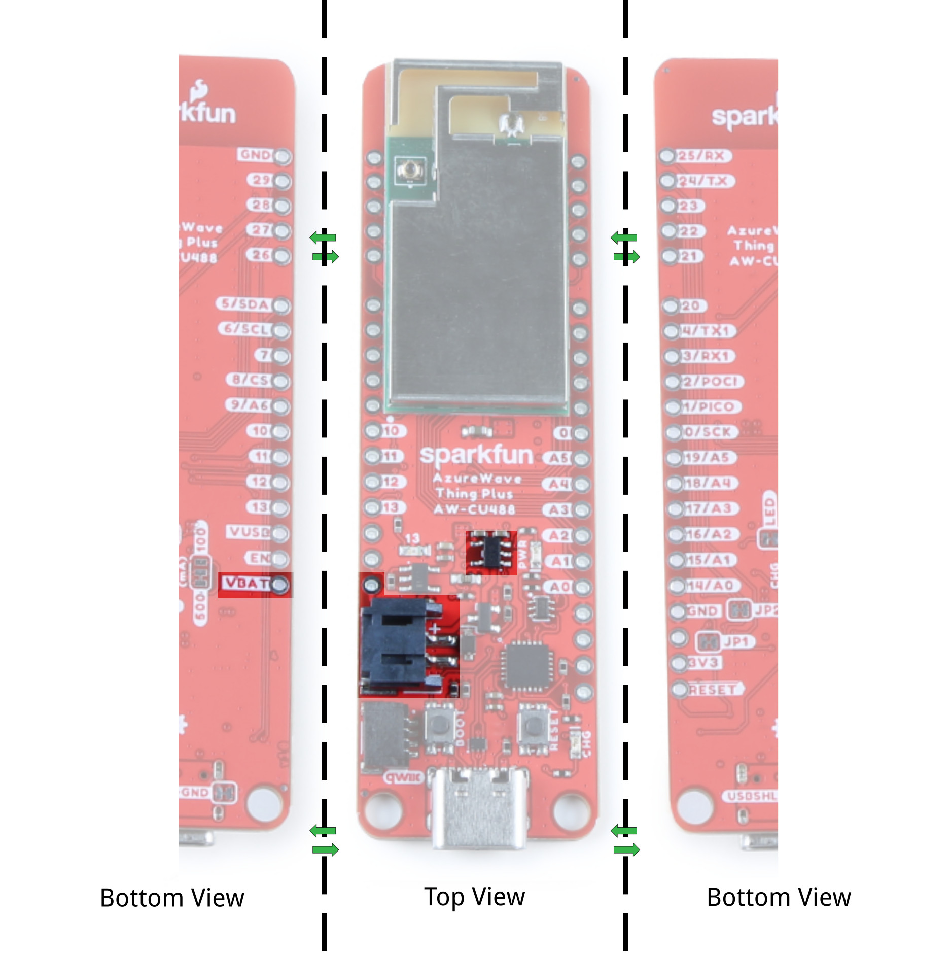
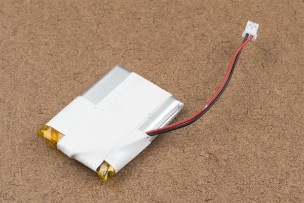
LiPo Battery
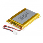
A single-cell Lithium-ion battery can be connected to the AzureWave Thing Plus (AW-CU488) for portability.


Suggested Reading
If you aren't familiar with the Qwiic system, we recommend reading here for an overview if you decide to take advantage of the Qwiic connector.
| Qwiic Connect System |
We would also recommend taking a look at the following tutorials if you aren't familiar with them.
How to Solder: Through-Hole Soldering
Installing Arduino IDE
Arduino Shields v2
Installing Board Definitions in the Arduino IDE
Serial Communication
Serial Peripheral Interface (SPI)
Analog vs. Digital
Noisy Cricket Stereo Amplifier - 1.5W Hookup Guide
Analog MEMS Microphone Breakout - SPH8878LR5H-1 Hookup Guide
Hardware Overview
In this section, we will highlight the hardware and pins that are broken out on the AzureWave Thing Plus (AW-CU488). For more information, check out our Resources and Going Further for more information on the AzureWave AW-CU488 module or the Realtek RTL8721DM that is contained within the module.
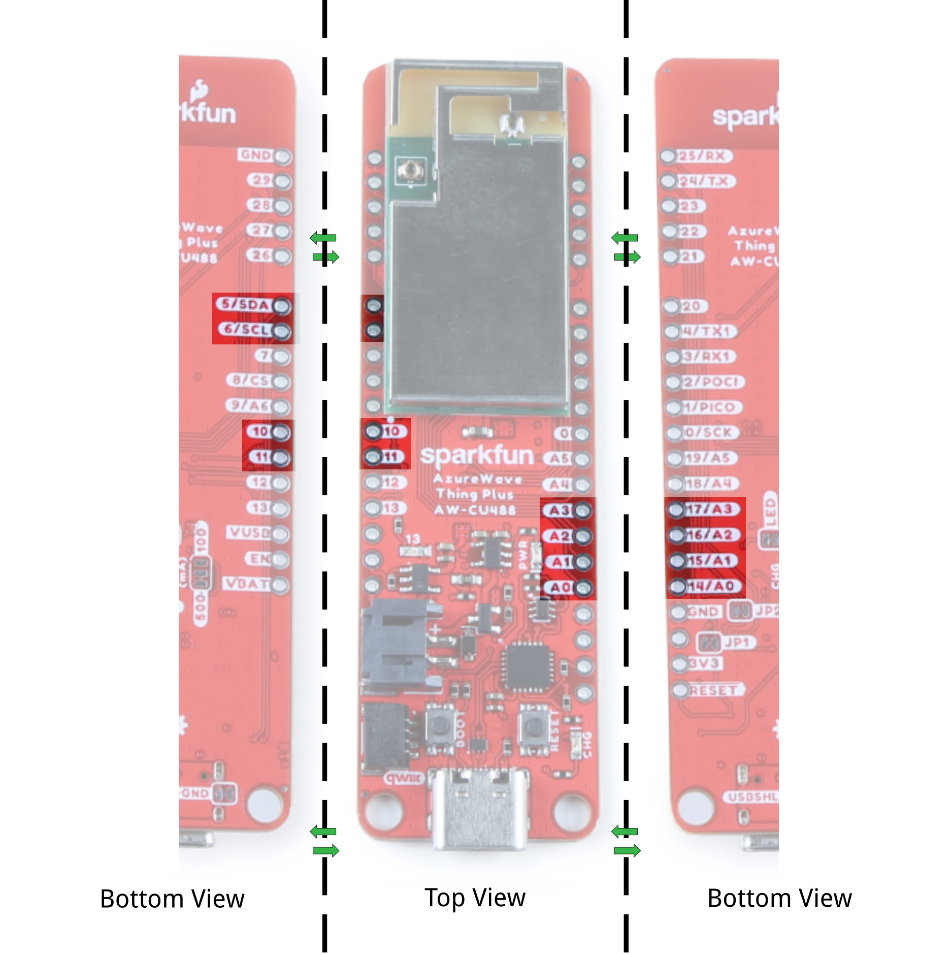
GPIO
The AzureWave Thing Plus breaks out the GPIO pins to plated through hole pads on the edge of the board using the Thing Plus/ Feather Form Factor. Additional 1x5 pins are broken out along the extended part of the board.
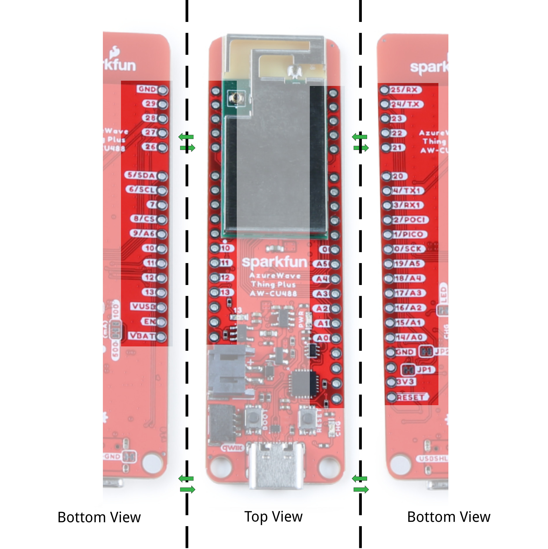
Note that the pin label might have additional functionality. Below is a graphical datasheet of the AzureWave Thing Plus (AW-CU488) that highlights the additional functionality.
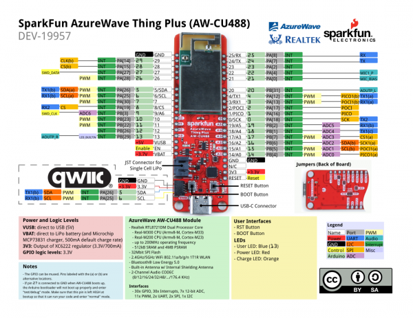
27 is connected to GND when AW-CU488 boots up, the Arduino bootloader will not boot up properly and enter "test/debug" mode. Make sure that this pin is left HIGH at bootup so that it can run your code and enter "normal" mode.
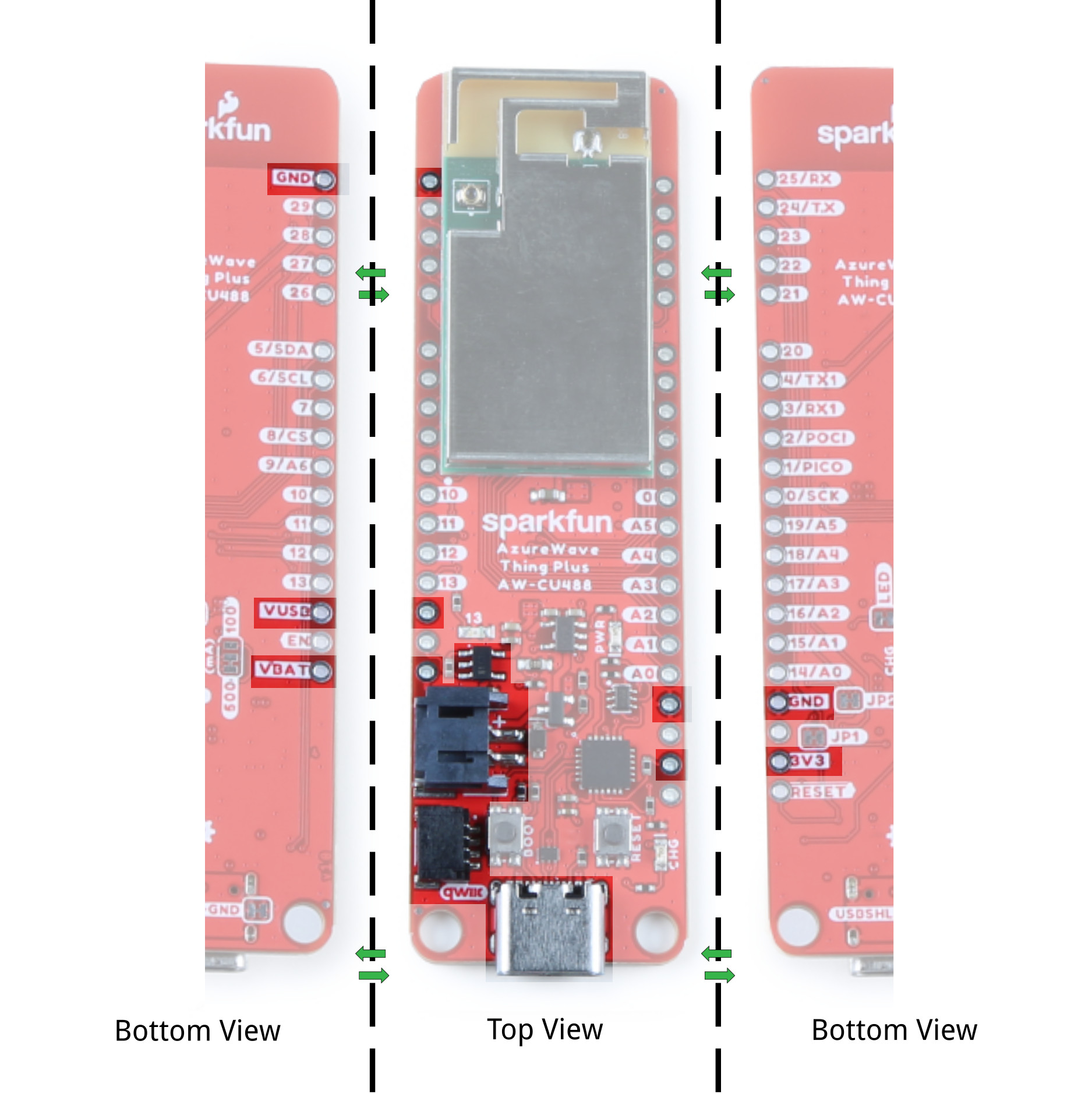
Power
There are a variety of power and power-related nets broken out to connectors and through hole pads. Power is regulated down to 3.3V for the AW-CU488 so the logic level is 3.3V for the I/O.
- VBUS: The VBUS net is connected to the USB Type C connector and the VBUS PTH. You can use 5V from a USB port by connecting to the USB Type C connector or connecting power to the VBUS PTH. Make sure that power you provide to this pin does not exceed 6 volts. Power is regulated down with the XC6222 3.3V/700mA voltage regulator. The USB Type C connector is also used to upload code to your processor, send serial data to a terminal window, or charging the LiPo battery. Of course for portable power, you could connect a USB battery as an alternative to using a LiPo battery.
- VBAT: The VBAT net is connected to the 2-pin JST connector, VBAT PTH, and the AW-CU488's VBAT MEAS pin. For portable applications, you can connect a nominal 3.7V single cell, LiPo battery to the 2-pin JST connector. This pin is also connected to the MCP73831 charge IC to safely charge the LiPo battery to its maximum voltage of about 4.2V. We recommend connecting only LiPo batteries to the VBAT net to power the board. Of course, you can power a separate device through the VBAT PTH pin. Power is regulated down with the XC6222 3.3V/700mA voltage regulator.
- 3V3: The 3.3V net is labeled as 3V3. You can apply power to the board if you have a regulated voltage of 3.3V. Otherwise, you could power a separate device through the 3V3 PTH pin. This is also connected to the Qwiic connector's 3.3V pin to power Qwiic enabled devices.
- GND: of course, is the common, ground voltage (0V reference) for the system.
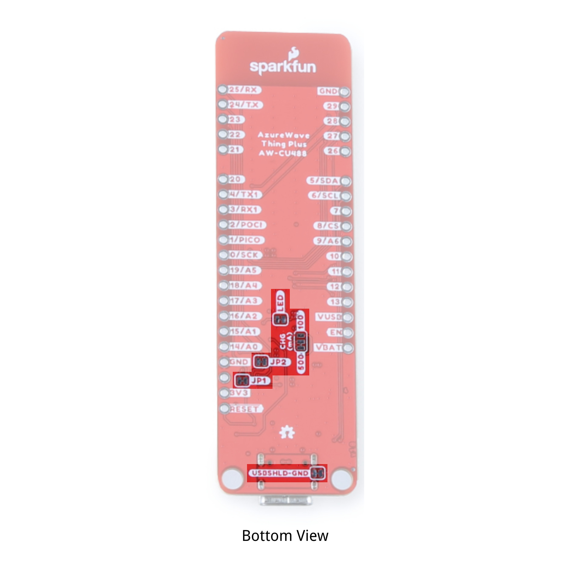
LiPo Charge Circuit
The board includes the MCP73831 LiPo charger IC (the little black IC with 5 pins) to safely charge a single cell, LiPo battery. In this case, the charge rate is set to a default rate of 500mA. Cutting the trace in the back and adding a solder jumper between the middle pad and the pad labeled as 100mA will set the charge rate to 100mA. The on-board LED labeled as CHG can be used to get an indication of the charge status of your battery.
Reset and Boot Buttons
Each board includes a RESET and BOOT button. There is an additional reset PTH next to the reset button. Hit the reset button to restart the AW-CU488. To manually place the AW-CU488 into boot mode, hold down the BOOT button while pressing the RESET button momentarily and then release the BOOT button. As a side note, the BOOT button is also connected to pin 24 (TX). The datasheet refers to this pin as the CHIP_EN.
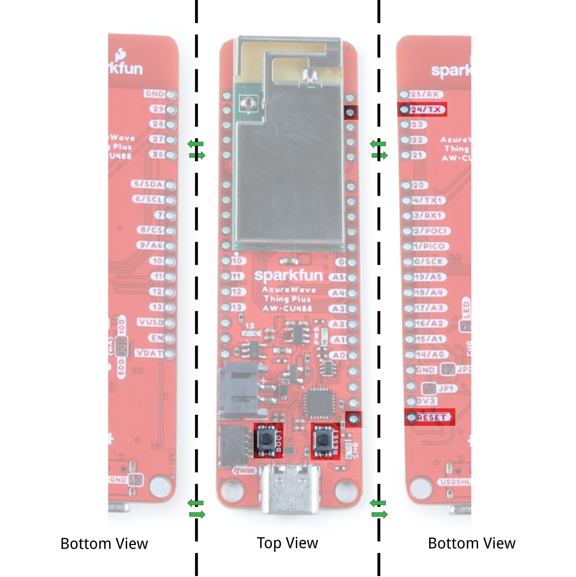
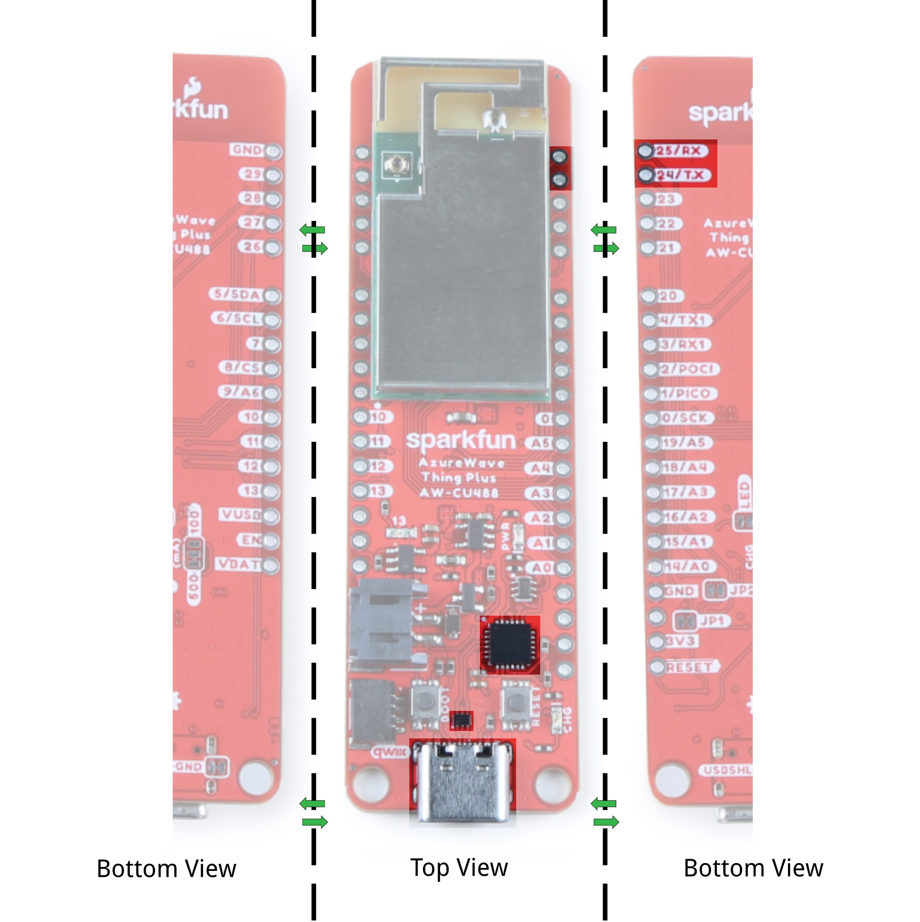
CP210X USB-to-Serial Converter
The board includes a USB-to-Serial converter. This is used for serial programming or communicating with a serial terminal. The CP210X's TX pin is connected to pin 25 (RX) while and RX pin is connected to pin 24 (TX).
UART
There are two UART ports broken out. The primary UART is connected to pins 24 (TX) and 25 (RX). As stated earlier, these pins are connected to the BOOT button and USB-to-Serial converter. The secondary UART is connect to pins 4 (TX1) and 3 (RX1).

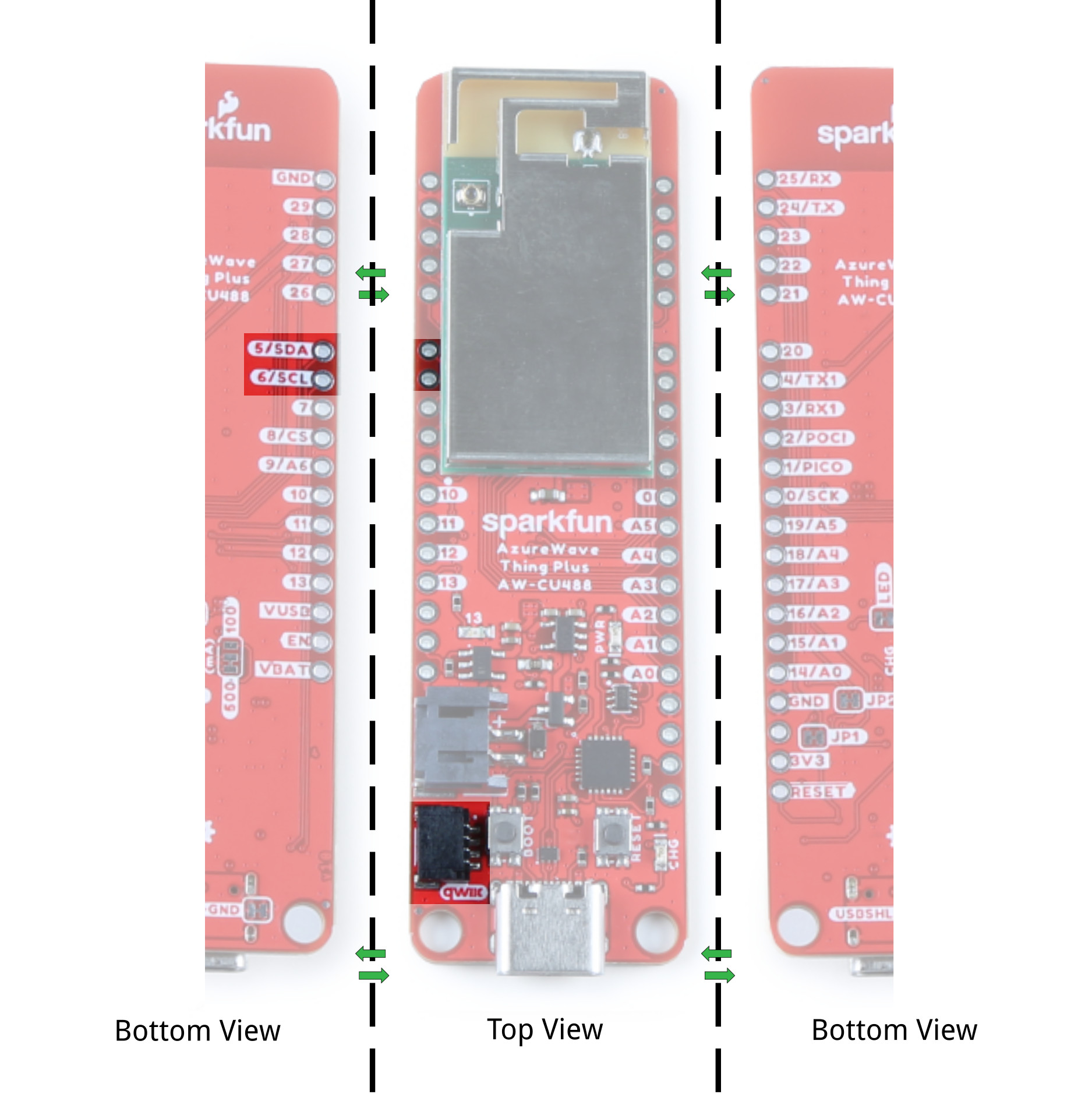
Qwiic and I2C
The board includes a horizontal Qwiic connector. These pins are connected to the primary I2C bus and 3.3V power allowing you to easily add a Qwiic-enabled device to your application. The I2C SCL pin is connected to 6. The I2C SDA is connected to 5.
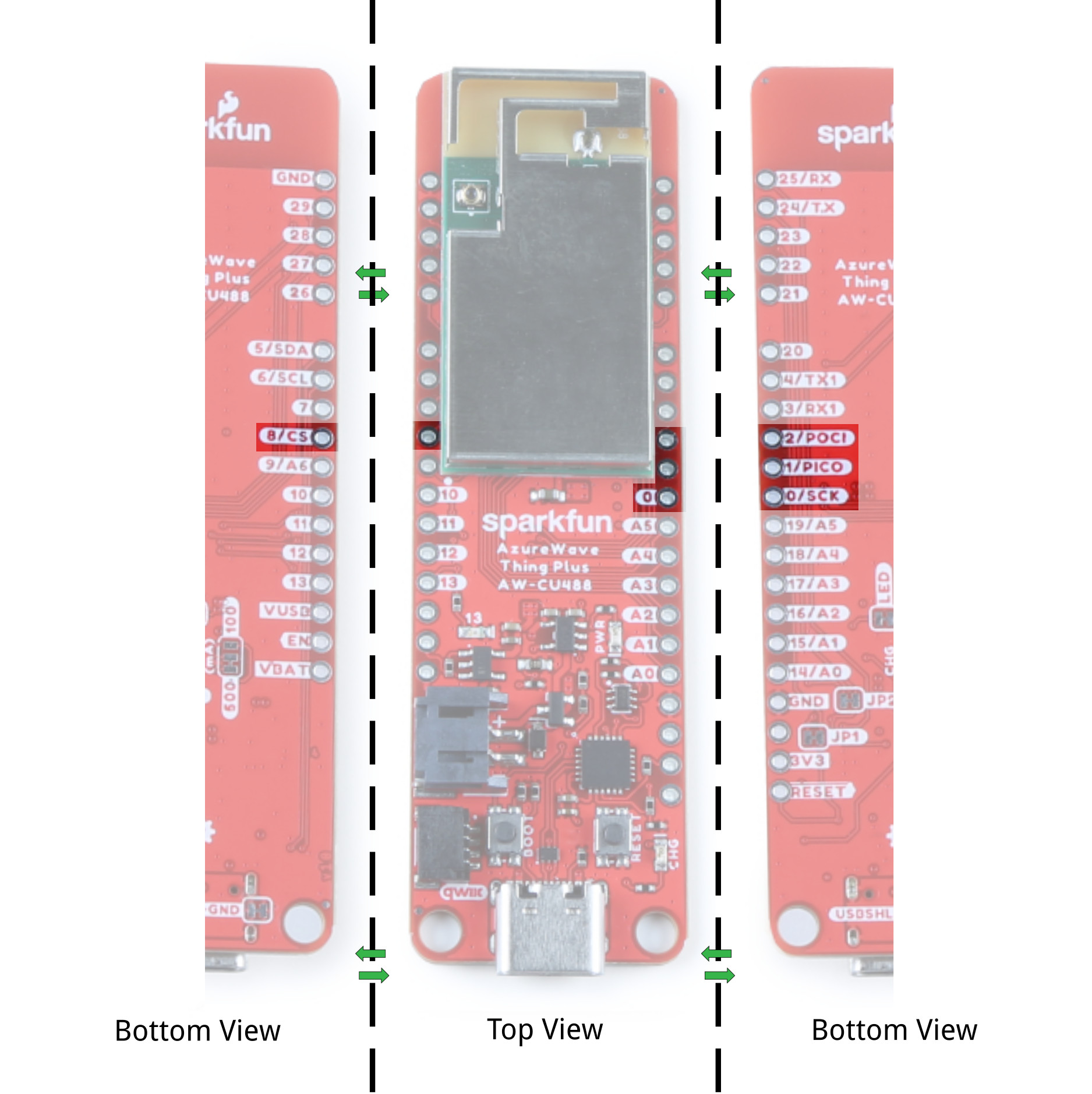
SPI
The primary SPI pins are on pin 0 (SCK), 1 (PICO), 2 (POCI), and 8 (CS).
Analog
There are six analog pins available on pins 14 (A0), 15 (A1), 16 (A2), 17 (A3), 18 (A4), 19 (A5), and 9 (A6).

A0-A6) before including the library.
int analog_pin = A2;  //<=== Add this line before including Audio Codec library

#include "AudioCodec.h" //include Audio Codec Arduino library
#include "FFT.h"
Pulse Width Modulation (PWM)
The board includes 11x PWM pins. These can be found on the pinout table listed earlier in this section: 3, 4, 5, 6, 7, 10, 11, 14, 15, 17, and 26.
BOARD_RTL8721DM. For example, in the ServoSweep.ino file, they attach PWM pin 3 to servo object. You would need to adjust pin 3 to another PWM pin that is available on the AzureWave Thing Plus (AW-CU488).
  .
  .
  .
  #elif defined(BOARD_RTL8721DM)
    // attaches the servo on PWM pin 3 to the servo object
    myservo.attach(3);
Audio Codec Input Microphone and Analog Output Pins
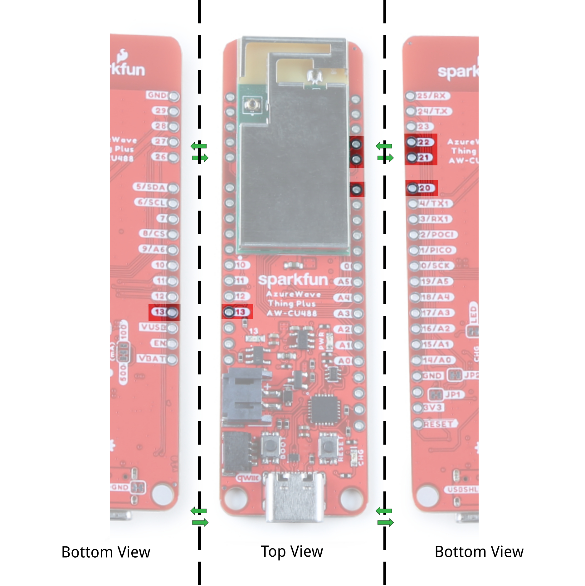
Not labeled on the board is the microphone pins. Pin 21 is also the "MIC_BIAS" while the 22 is also the right microphone "MIC1_R." The analog output for the right and left speakers are on pin 13 (or "AOUTP_R") and pin 20 (or "AOUTP_L"). Note that the LED is tied to pin 13. We recommend using a different output pin for the LED if you decide to use this pin for the audio code.
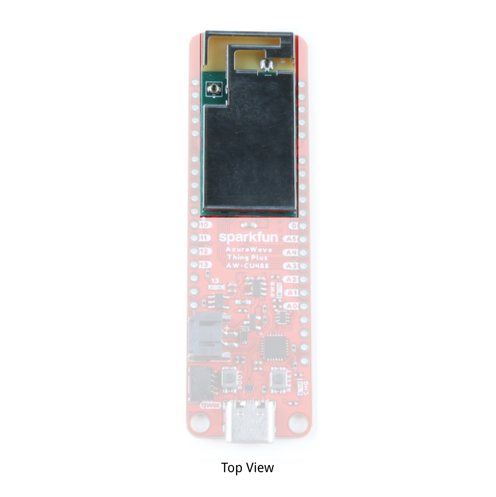
Antenna
The AzureWave AW-CU488 module includes an internal shielding antenna. Note that the connector that looks similar to a "u.FL" connector is used for production testing and is not available to the user.
LEDs
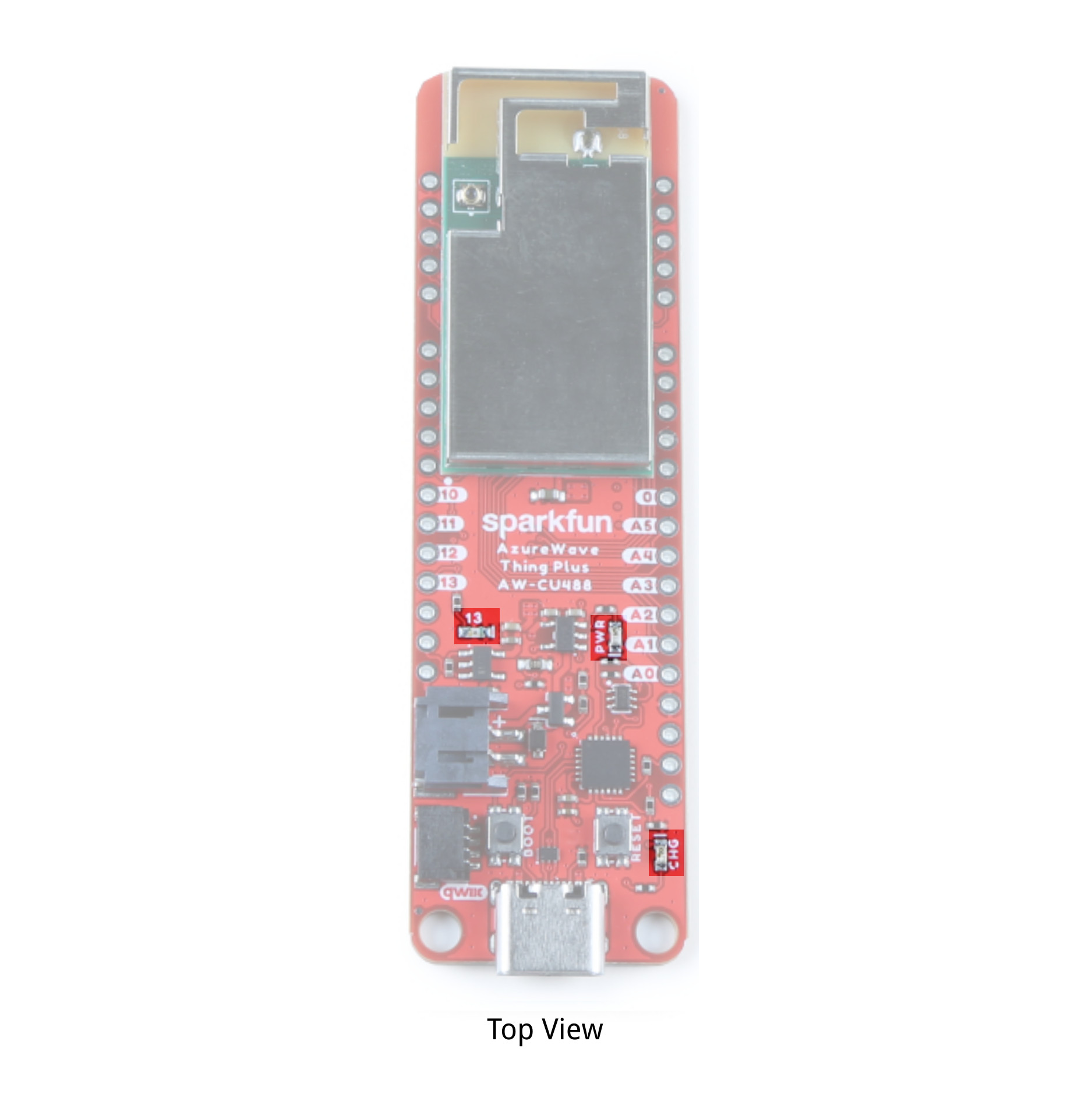
The board includes three status LEDs.
- PWR - The PWR LED lights up to indicate when there is a 3.3V available after power is regulated down from the USB connector or LiPo battery. This can be disabled by cutting the jumper labeled as LED.
- 13 - The 13 LED can be configured by the user and is connected to pin 13. Note that this is also connected to the analog output "AOUTP_R". You will need to decide between using this pin for an LED or the analog output pin.
- CHG - The on-board yellow CHG LED can be used to get an indication of the charge status of your battery. Below is a table of other status indicators depending on the state of the charge IC.
| Charge State | LED status |
| No Battery | Floating (should be OFF, but may flicker) |
| Shutdown | Floating (should be OFF, but may flicker) |
| Charging | ON |
| Charge Complete | OFF |
Jumpers
The following jumpers are included.
- CHG - This three way jumper sets the charge IC's charge rate. By default, it's connected to the 500mA. Cutting a trace and adding a solder jumper between the center pad and the pad labeled as 100mA will set the charge rate to 100mA
- USBSHLD-GND - This jumper connects the USB Type C connector's shield pin to GND. Cut this to isolate the USB Type C connector's shield pin. This is for advanced users that want to ground their board to their enclosure instead of the ground plane.
- LED - By default, this jumper is closed and located on the bottom of the board. Cut this trace to disable the power LED that is connected to 3.3V.
- JP1 - This jumper is connected to the auto-boot circuit by default. This is for advanced users that want to disable the auto-boot when uploading code. You will need to cut this jumper with JP2.
- JP2 - This jumper is connected to the auto-boot circuit by default. This is for advanced users that want to disable the auto-boot when uploading code. You will need to cut this jumper with JP1.
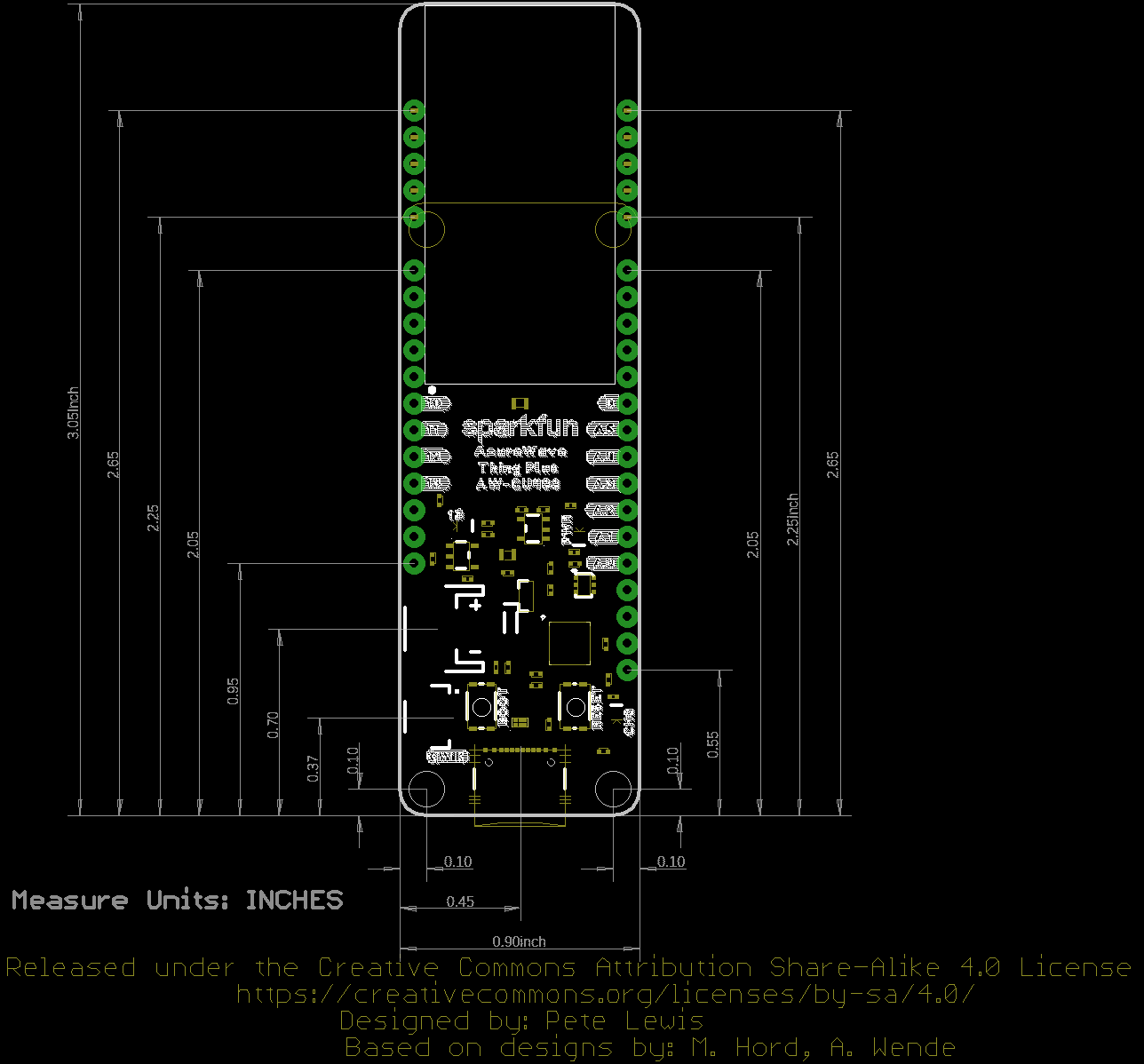
Board Dimensions
The board uses the Thing Plus footprint. Due to the size of the module, there are two mounting holes and the length of the board is extended to accommodate the size of the AW-CU488 module. Thus the board is about 3.05" x 0.90" (or 77.47 mm x 22.86 mm).
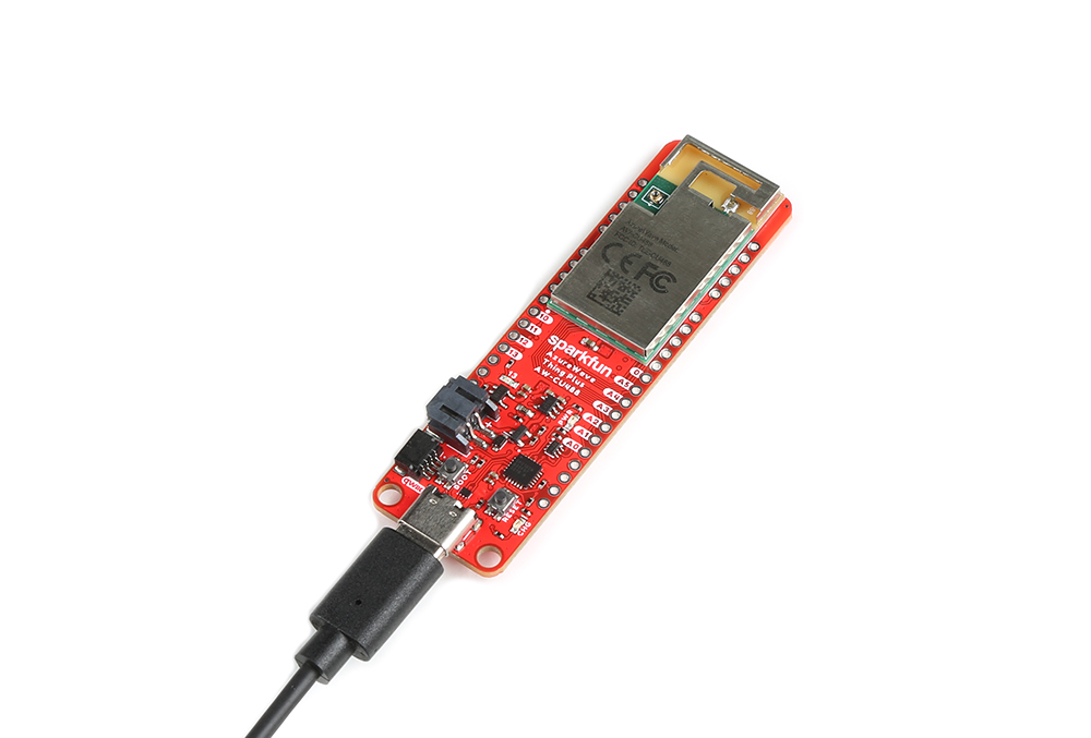
Hardware Hookup
At a minimum, plug in the USB C cable to the AzureWave Thing Plus to power and program the board.
Installing the CP2104 USB Driver
You will also need to install the SiLabs CP2104 Driver, which can be found here: USB to UART Bridge VCP Driver
Setting Up Arduino
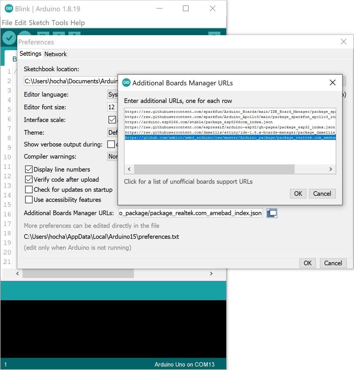
Install Realtek Board Add-On
First, open your Arduino preferences (File > Preferences). Then find the Additional Board Manager URLs text box, and paste the below link in. If you have other links for other 3rd party boards, you will need to add a comma (,) between each link in the field. You can also open an additional window by clicking the window button next to the Additional Boards Manager URLs: field and add the link to a separate line.
language:bash
https://github.com/ambiot/ambd_arduino/raw/master/Arduino_package/package_realtek.com_amebad_index.json
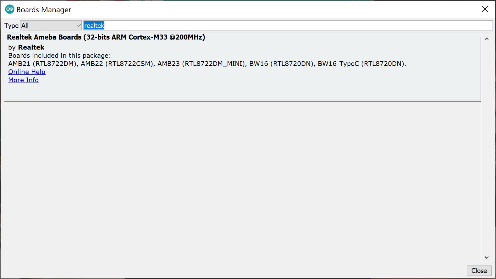
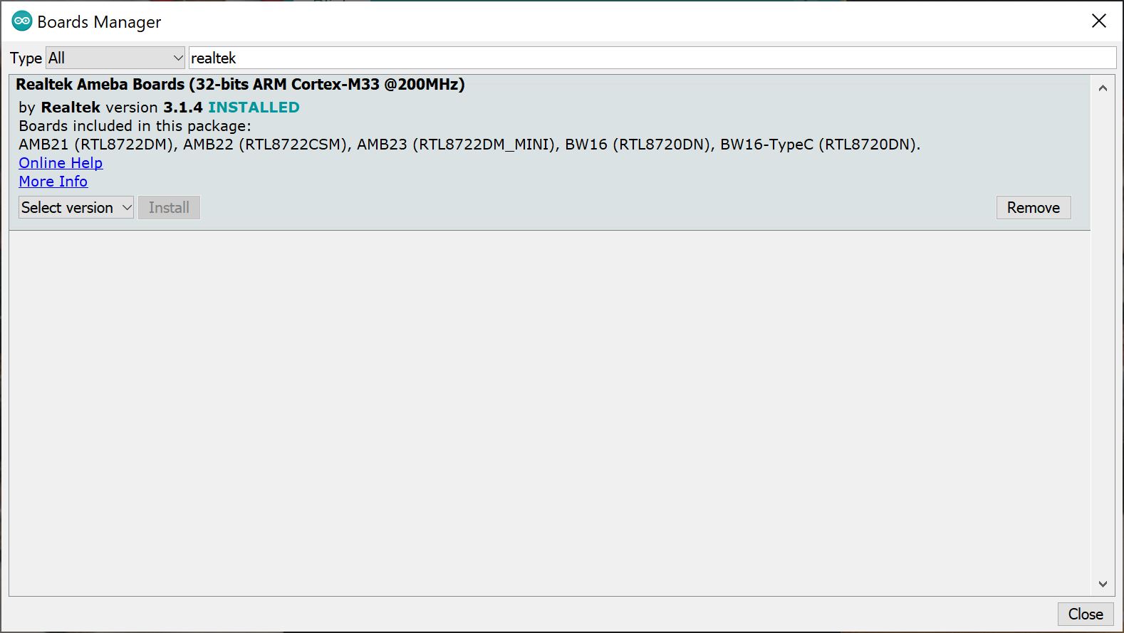
Then hit "OK", and travel back to the Board Manager menu. Type "realtek" in the search bar and hit enter. Click on the "Install" button for the Realtek Ameba Boards (32-bits ARM Cortex-M33 @200MHz) by Realtek. Downloading and installing the tools may take a couple minutes. Feel free to walk around, grab some water, or do a little dance while the tools install.
Once installed, Arduino-blue "INSTALLED" text should appear next to the boards list entry.
Selecting the AzureWave Thing Plus Board
To upload code to the board, you will need to select the correct board. From the menu, select the following: Tools > Board > AW-CU488 Thing Plus (RTL8721DM) .
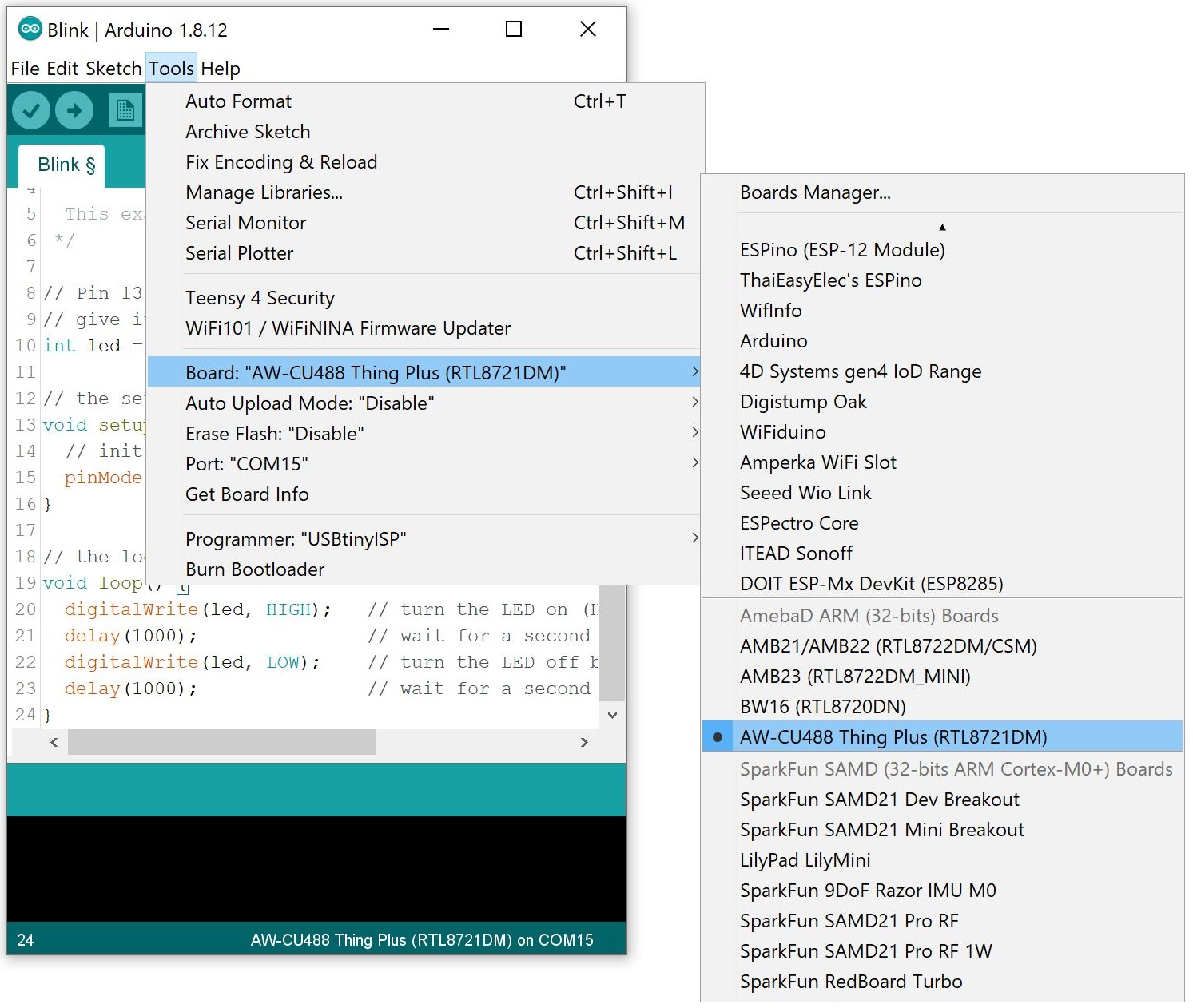
There are a few options for the board. One of them is the option to automatically upload code to the board without the need to press the BOOT and RESET buttons as Arduino uploads your code. By default, the Auto Upload Mode is disabled. From the menu, select the following: Tools > Auto Upload Mode: > Enable .

COM Port Selection
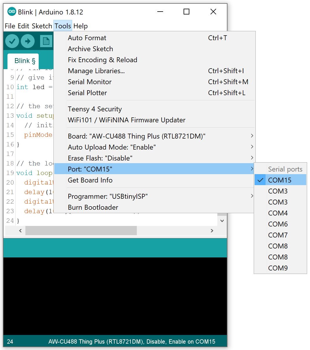
You will also need to select the COM port that the board enumerated to. From the menu, select your respective COM port on your computer (in this case, it was COM15 on a Windows computer): Tools > Port > COM___ .
Example 1: Blink
Required Materials
To follow along with this part of the tutorial, you will need one AzureWave Thing Plus board and USB C cable.
Hardware Hookup
The connection is the same as explained earlier in the tutorial. Connect the USB cable to the AzureWave Thing Plus (AW-CU488).
Example Code
Let's upload a sketch to the board. Copy and paste the following code in the Arduino IDE. Select the correct board definition from the menu (in this case, Tools > Boards > AW-CU488 Thing Plus (RTL8721DM)). Then select the correct COM port that the board enumerated to (in this case, it was COM15). Hit upload button.
language:c
/*
  Blink
  Turns on an LED on for one second, then off for one second, repeatedly.

  This example code is in the public domain.
 */

// Pin 13 has an LED connected on most Arduino boards.
// give it a name:
int led = 13; //LED is connected to pin 13 on the AzureWave Thing Plus (AW-CU488)

// the setup routine runs once when you press reset:
void setup() {
  // initialize the digital pin as an output.
  pinMode(led, OUTPUT);
}

// the loop routine runs over and over again forever:
void loop() {
  digitalWrite(led, HIGH);   // turn the LED on (HIGH is the voltage level)
  delay(1000);               // wait for a second
  digitalWrite(led, LOW);    // turn the LED off by making the voltage LOW
  delay(1000);               // wait for a second
}
LED_BUILTIN.
Once uploaded, check the LED labeled as 13 on the board. It should be blinking on and off every second! Sweet!
Example 2: Scanning WiFi Networks
Required Materials
To follow along with this part of the tutorial, you will need one AzureWave Thing Plus board and USB C cable.
Hardware Hookup
The connection is the same as explained earlier in the tutorial. Connect the USB cable to the AzureWave Thing Plus (AW-CU488). Of course, you will need a wireless router capable of 2.4GHz and 5GHz.
Example Code
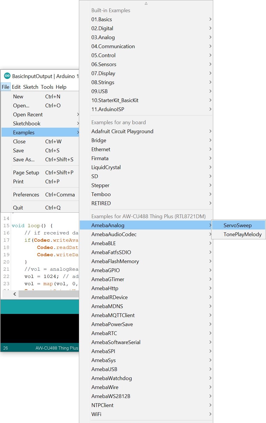
Let's upload the sketch to scan local WiFi networks in your area. From the menu, select the following: File > Examples > Examples for AW_CU488 Thing Plus (RTL8721DM) | WiFi > ScanNetworks.
Or you can copy and paste the following code in the Arduino IDE. Select the correct board definition from the menu (in this case, Tools > Boards > AW-CU488 Thing Plus (RTL8721DM)). Then select the correct COM port that the board enumerated to (in this case, it was COM21). Hit upload button.
language:c
/*

 This example  prints the Wifi shield's MAC address, and
 scans for available Wifi networks using the Wifi shield.
 Every ten seconds, it scans again. It doesn't actually
 connect to any network, so no encryption scheme is specified.

 Circuit:
 * WiFi shield attached

 created 13 July 2010
 by dlf (Metodo2 srl)
 modified 21 Junn 2012
 by Tom Igoe and Jaymes Dec
 */


#include <WiFi.h>

void setup() {
    //Initialize serial and wait for port to open:
    Serial.begin(115200);
    while (!Serial) {
        ; // wait for serial port to connect. Needed for native USB port only
    }

    // check for the presence of the shield:
    if (WiFi.status() == WL_NO_SHIELD) {
        Serial.println("WiFi shield not present");
        // don't continue:
        while (true);
    }

    // Print WiFi MAC address:
    printMacAddress();
}

void loop() {
    // scan for existing networks:
    Serial.println("Scanning available networks...");
    listNetworks();
    delay(10000);
}

void printMacAddress() {
    // the MAC address of your Wifi shield
    byte mac[6];

    // print your MAC address:
    WiFi.macAddress(mac);
    Serial.print("MAC: ");
    Serial.print(mac[0], HEX);
    Serial.print(":");
    Serial.print(mac[1], HEX);
    Serial.print(":");
    Serial.print(mac[2], HEX);
    Serial.print(":");
    Serial.print(mac[3], HEX);
    Serial.print(":");
    Serial.print(mac[4], HEX);
    Serial.print(":");
    Serial.println(mac[5], HEX);
}

void listNetworks() {
    // scan for nearby networks:
    Serial.println("** Scan Networks **");
    int numSsid = WiFi.scanNetworks();
    if (numSsid == -1) {
        Serial.println("Couldn't get a wifi connection");
        while (true);
    }

    // print the list of networks seen:
    Serial.print("number of available networks:");
    Serial.println(numSsid);

    // print the network number and name for each network found:
    for (int thisNet = 0; thisNet < numSsid; thisNet++) {
        Serial.print(thisNet);
        Serial.print(") ");
        Serial.print(WiFi.SSID(thisNet));
        Serial.print("\tSignal: ");
        Serial.print(WiFi.RSSI(thisNet));
        Serial.print(" dBm");
        Serial.print("\tEncryptionRaw: ");
        printEncryptionTypeEx(WiFi.encryptionTypeEx(thisNet));
        Serial.print("\tEncryption: ");
        printEncryptionType(WiFi.encryptionType(thisNet));
    }
}

void printEncryptionTypeEx(uint32_t thisType) {
    /*  Arduino wifi api use encryption type to mapping to security type.
    *  This function demonstrate how to get more richful information of security type.
    */
    switch (thisType) {
        case SECURITY_OPEN:
            Serial.print("Open");
            break;
        case SECURITY_WEP_PSK:
            Serial.print("WEP");
            break;
        case SECURITY_WPA_TKIP_PSK:
            Serial.print("WPA TKIP");
            break;
        case SECURITY_WPA_AES_PSK:
            Serial.print("WPA AES");
            break;
        case SECURITY_WPA2_AES_PSK:
            Serial.print("WPA2 AES");
            break;
        case SECURITY_WPA2_TKIP_PSK:
            Serial.print("WPA2 TKIP");
            break;
        case SECURITY_WPA2_MIXED_PSK:
            Serial.print("WPA2 Mixed");
            break;
        case SECURITY_WPA_WPA2_MIXED:
            Serial.print("WPA/WPA2 AES");
            break;
    }
}

void printEncryptionType(int thisType) {
    // read the encryption type and print out the name:
    switch (thisType) {
        case ENC_TYPE_WEP:
            Serial.println("WEP");
            break;
        case ENC_TYPE_TKIP:
            Serial.println("WPA");
            break;
        case ENC_TYPE_CCMP:
            Serial.println("WPA2");
            break;
        case ENC_TYPE_NONE:
            Serial.println("None");
            break;
        case ENC_TYPE_AUTO:
            Serial.println("Auto");
            break;
    }
}
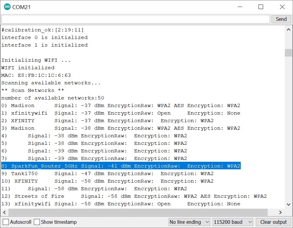
Open you Arduino Serial Monitor at 115200. The AzureWave Thing Plus (AW-CU488) will begin scanning your area. Take note of the encryption type of the WiFi network that you are connecting to. In this case, I had set my home WiFI Router's 5GHz network name to "SparkFun_Router_5GHz" and it was using a WPA2 encryption (as highlighted in the Arduino Serial Monitor).
Example 3: Connecting to a WiFi Network
Required Materials
To follow along with this part of the tutorial, you will need one AzureWave Thing Plus board and USB C cable.
Hardware Hookup
The connection is the same as explained earlier in the tutorial. Connect the USB cable to the AzureWave Thing Plus (AW-CU488). Again, you will need a wireless router capable of 2.4GHz and 5GHz.
Example Code
Let's upload the sketch to connect to the 5GHz network in your area. From the menu, select the following: File > Examples > Examples for AW_CU488 Thing Plus (RTL8721DM) | WiFi > ConnectWithWiFi > ConnectWithWPA. Depending on your encryption, you may select a different example.
Or you can copy and paste the following code in the Arduino IDE.
language:c
/*

 This example connects to an unencrypted Wifi network.
 Then it prints the  MAC address of the Wifi shield,
 the IP address obtained, and other network details.

 Circuit:
 * WiFi shield attached

 created 13 July 2010
 by dlf (Metodo2 srl)
 modified 31 May 2012
 by Tom Igoe
 */
#include <WiFi.h>

// If you are connecting to an iPhone WiFi hotspot, the default SSID uses Unicode (U+2019) Right Single Quotation Mark instead of ASCII apostrophe
// Modify the "Your Name" section in the SSID below to connect to an iPhone using a default SSID style
// char ssid[] = "Your Name\xE2\x80\x99s iPhone";

// UTF-8 encoding can also be used for SSID with emoji characters
// Emoji characters can be converted into UTF-8 at https://mothereff.in/utf-8
// char ssid[] = "\xe2\x9c\x8c\xef\xb8\x8f Ameba \xe2\x9c\x8c\xef\xb8\x8f";

char ssid[] = "yourNetwork";     //  your network SSID (name)
char pass[] = "secretPassword";  // your network password
int status = WL_IDLE_STATUS;     // the Wifi radio's status

void setup() {
    //Initialize serial and wait for port to open:
    Serial.begin(115200);
    while (!Serial) {
        ; // wait for serial port to connect. Needed for native USB port only
    }

    // check for the presence of the shield:
    if (WiFi.status() == WL_NO_SHIELD) {
        Serial.println("WiFi shield not present");
        // don't continue:
        while (true);
    }

    // attempt to connect to Wifi network:
    while (status != WL_CONNECTED) {
        Serial.print("Attempting to connect to WPA SSID: ");
        Serial.println(ssid);
        // Connect to WPA/WPA2 network:
        status = WiFi.begin(ssid, pass);

        // wait 10 seconds for connection:
        delay(10000);
    }

    // you're connected now, so print out the data:
    Serial.println();
    Serial.print("You're connected to the network");
    printCurrentNet();
    printWifiData();
}

void loop() {
    // check the network connection once every 10 seconds:
    delay(10000);
    printCurrentNet();
}

void printWifiData() {
    // print your WiFi shield's IP address:
    IPAddress ip = WiFi.localIP();
    Serial.print("IP Address: ");
    Serial.println(ip);
    Serial.println(ip);

    // print your MAC address:
    byte mac[6];
    WiFi.macAddress(mac);
    Serial.print("MAC address: ");
    Serial.print(mac[0], HEX);
    Serial.print(":");
    Serial.print(mac[1], HEX);
    Serial.print(":");
    Serial.print(mac[2], HEX);
    Serial.print(":");
    Serial.print(mac[3], HEX);
    Serial.print(":");
    Serial.print(mac[4], HEX);
    Serial.print(":");
    Serial.println(mac[5], HEX);
}

void printCurrentNet() {
    // print the SSID of the network you're attached to:
    Serial.print("SSID: ");
    Serial.println(WiFi.SSID());

    // print the MAC address of the router you're attached to:
    byte bssid[6];
    WiFi.BSSID(bssid);
    Serial.print("BSSID: ");
    Serial.print(bssid[5], HEX);
    Serial.print(":");
    Serial.print(bssid[4], HEX);
    Serial.print(":");
    Serial.print(bssid[3], HEX);
    Serial.print(":");
    Serial.print(bssid[2], HEX);
    Serial.print(":");
    Serial.print(bssid[1], HEX);
    Serial.print(":");
    Serial.println(bssid[0], HEX);

    // print the received signal strength:
    long rssi = WiFi.RSSI();
    Serial.print("signal strength (RSSI):");
    Serial.println(rssi);

    // print the encryption type:
    byte encryption = WiFi.encryptionType();
    Serial.print("Encryption Type:");
    Serial.println(encryption, HEX);
    Serial.println();
}
Then adjust the arrays that holed the SSID (i.e. yourNetwork) and password (secretPassword) based on your WiFi network's settings.
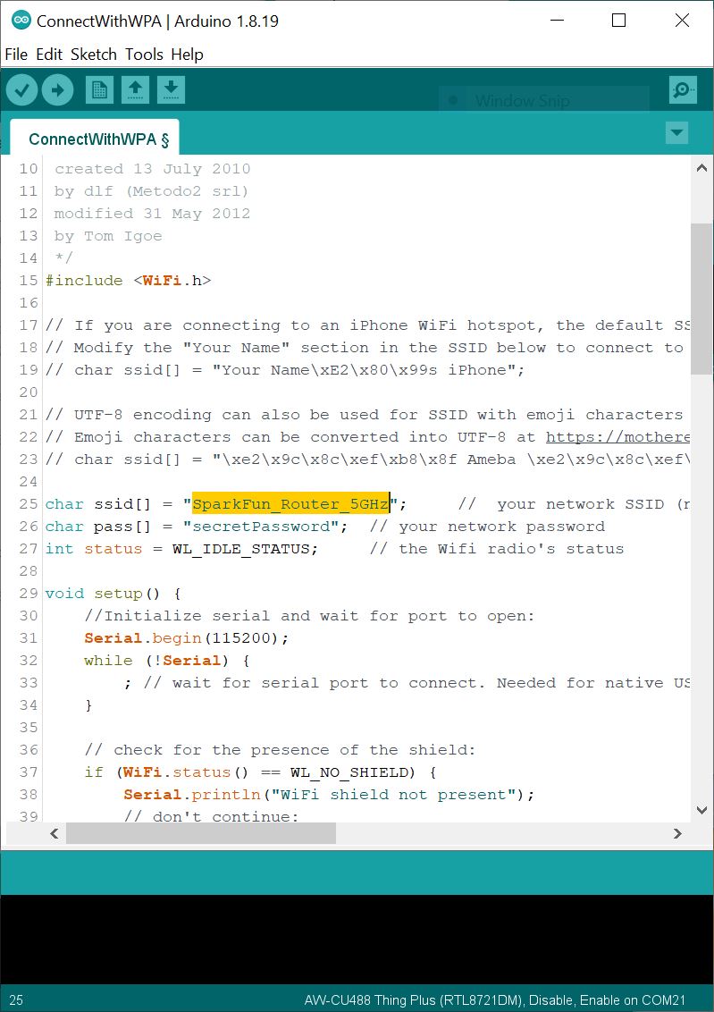
Select the correct board definition from the menu (in this case, Tools > Boards > AW-CU488 Thing Plus (RTL8721DM). Then select the correct COM port that the board enumerated to (in this case, it was COM21). Hit upload button.
Open the Arduino Serial Monitor at 115200. The AzureWave Thing Plus (AW-CU488) will attempt to connect to the network.
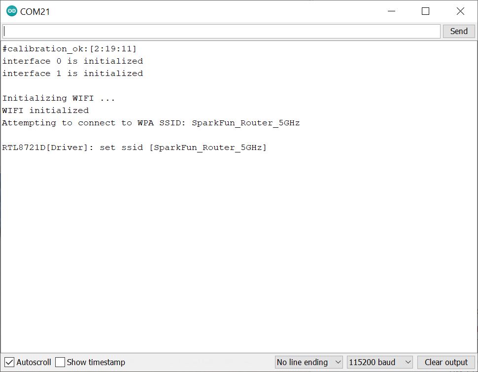
If all goes well, you should see some status outputs and message indicating that you are connected to your network! In this case, I had the following message:
language:bash
You're connected to the networkSSID: SparkFun_Router_5GHz
The serial output will then continue outputting the status of the connection some of which include the SSID, signal strenth (RSSI), and encryption type. If you have admin privileges, you can check to see if the device is connected to the 5GHz WiFi network as well. Try connecting to a website and pulling the local time or weather in your area!
Example 4a: Audio Codec - Input Fast Fourier Transform (FFT)
Required Materials
To follow along with this part of the tutorial, you will need the following materials. You may not need everything though depending on what you have. Add it to your cart, read through the guide, and adjust the cart as necessary.
Hardware Hookup
For the following example, you will need the following connection as shown in the Fritzing diagram.
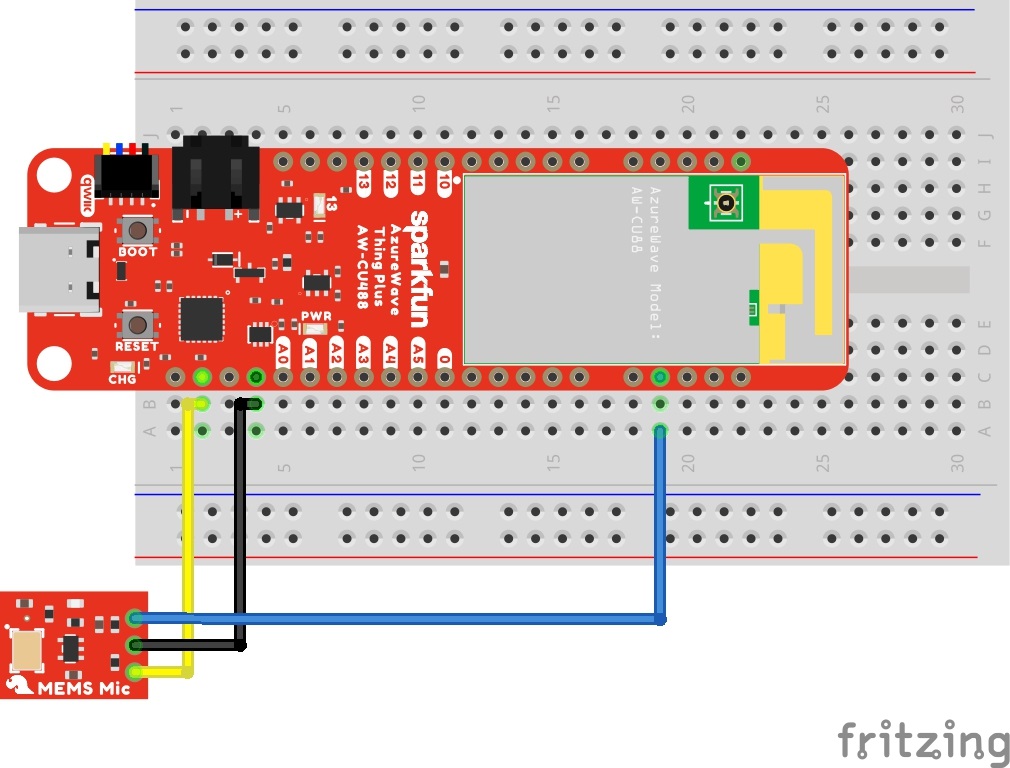
You will need to solder headers to the AzureWave Thing Plus (AW-CU488). Then solder headers on the MEMS microphone breakout. In this case, we soldered the straight headers at a right angle to connect a M/F jumper wire. Depending on your personal preference, you could also solder the headers on the MEMS microphone like the AzureWave Thing Plus (AW-CU488). Just make sure that the microphone input on the bottom side of the board faces away from the breadboard.
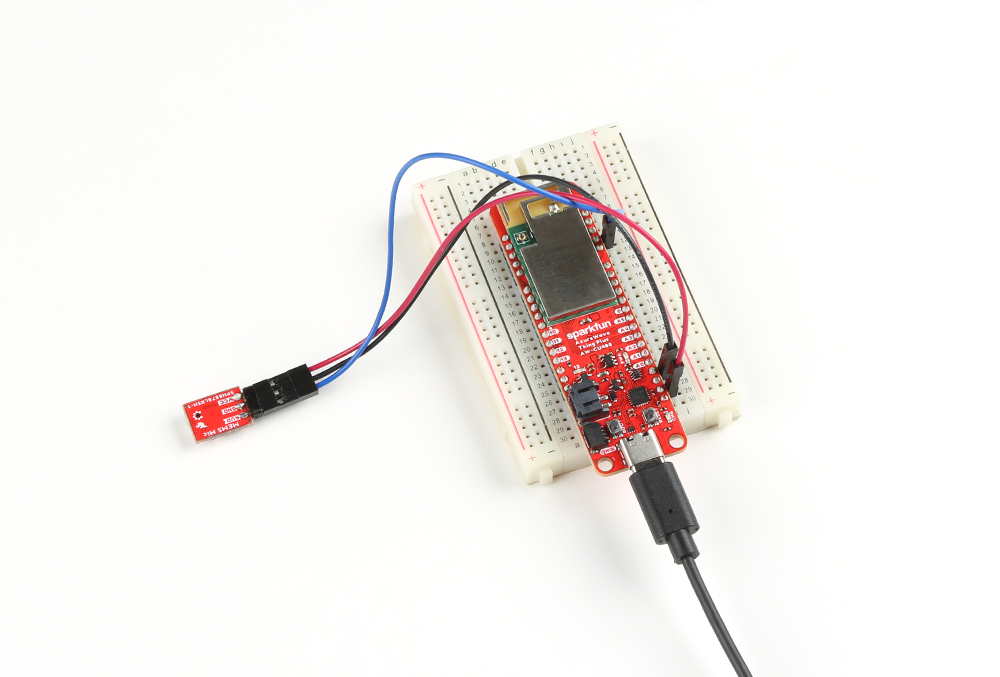
If you are using water soluble flux, make sure to clean off any flux residue remaining on the board. Make sure to be careful not to get any liquid into the MEMs microphone or the AW-CU488 module. Isopropyl alcohol and a Q-tip removes the water soluble flux pretty well. Then insert the board into the breadboard and connect the wires to the MEMS microphone. Finally, connect a USB C cable between the AzureWave Thing Plus (AW-CU488) and your computer's COM port.
Example Code
Let's upload the sketch to calculate the Fast Fourier Transform (FFT) of an audio signal. From the menu, select the following: File > Examples > Examples for AW_CU488 Thing Plus (RTL8721DM) | AmebaAudioCodec > InputFFT.
Or you can copy and paste the following code in the Arduino IDE. Select the correct board definition from the menu (in this case, Tools > Boards > AW-CU488 Thing Plus (RTL8721DM)). Then select the correct COM port that the board enumerated to (in this case, it was COM21). Hit upload button.
language:c
#include "AudioCodec.h"
#include "FFT.h"

#define SAMPLERATE 16000
#define SAMPLECOUNT 128

int16_t audio_buffer[SAMPLECOUNT] = {0};
float fft_buffer[SAMPLECOUNT/2] = {0};
uint16_t freq_bins[SAMPLECOUNT/2] = {0};
int i = 0;

FFT fft;

void setup() {
    Serial.begin(2000000);

    fft.setWindow(HANN, SAMPLECOUNT);
    fft.getFrequencyBins(freq_bins, SAMPLECOUNT, SAMPLERATE);

    for (i = 0; i < (SAMPLECOUNT/2); i++) {
        Serial.print(freq_bins[i]);
        Serial.print(" Hz | ");
    }
    Serial.println();

    Codec.setSampleRate(SAMPLERATE);
    Codec.begin(TRUE, FALSE);
}

void loop() {
    if(Codec.readAvaliable()) {
        Codec.readDataPage(audio_buffer, SAMPLECOUNT);    // read latest received data from buffer
        fft.calculate(audio_buffer, fft_buffer, SAMPLECOUNT);
        for (i = 0; i < (SAMPLECOUNT/2); i++) {
            if (fft_buffer[i] > 0.01) {
                Serial.print(fft_buffer[i],2);
                Serial.print(" | ");
            } else {
                Serial.print(" - |");
            }
        }
        Serial.println();
    }
    delay(1);
}
Open the Arduino Serial Monitor set to 2000000 will output the data similar to the output below. Each line will have a value in place for each frequency:
language:bash
0 Hz,125 Hz,250 Hz,375 Hz,500 Hz,625 Hz,750 Hz,875 Hz,1000 Hz,1125 Hz,1250 Hz,1375 Hz,1500 Hz,1625 Hz,1750 Hz,1875 Hz,2000 Hz,2125 Hz,2250 Hz,2375 Hz,2500 Hz,2625 Hz,2750 Hz,2875 Hz,3000 Hz,3125 Hz,3250 Hz,3375 Hz,3500 Hz,3625 Hz,3750 Hz,3875 Hz,4000 Hz,4125 Hz,4250 Hz,4375 Hz,4500 Hz,4625 Hz,4750 Hz,4875 Hz,5000 Hz,5125 Hz,5250 Hz,5375 Hz,5500 Hz,5625 Hz,5750 Hz,5875 Hz,6000 Hz,6125 Hz,6250 Hz,6375 Hz,6500 Hz,6625 Hz,6750 Hz,6875 Hz,7000 Hz,7125 Hz,7250 Hz,7375 Hz,7500 Hz,7625 Hz,7750 Hz,7875 Hz
Try blowing air across the input microphone or playing music from your smartphone. The FFT output will react to the input audio and split the signal into several bands. Better yet, try using a tone generator or playing a video that can generate an audio sample that reaches a desired frequency. The following video below is an audio sample that increases between 20Hz to 20kHz. Play the video below and watch the values for each frequency. You may need to adjust your speaker's volume. You will notice that the value will be the largest when the microphone hears a frequency that corresponds to the component. Adjacent components may be greater than 0 depending on your speaker's volume.
The example code breaks the audio sample into several components (it should be about half of the sample count, so 64 values for each line) which can make it hard to view through the Arduino Serial Monitor. Try outputting the data with comma separated values by replacing the spaces and | between each data with a comma '. If the value is less than 0.01, the value will be considered 0 instead of a -. Try scaling the values (i.e. multiplying the fft_buffer[i]*100) as well. This will help visualize the data through the Arduino Serial Plotter. Below is the modified example code with the changes described.
language:c
//modified inputFFT.ino for Comma Separated Values

#include "AudioCodec.h"
#include "FFT.h"

#define SAMPLERATE 16000
#define SAMPLECOUNT 128

int16_t audio_buffer[SAMPLECOUNT] = {0};
float fft_buffer[SAMPLECOUNT/2] = {0};
uint16_t freq_bins[SAMPLECOUNT/2] = {0};
int i = 0;

FFT fft;

void setup() {
    Serial.begin(2000000);

    fft.setWindow(HANN, SAMPLECOUNT);
    fft.getFrequencyBins(freq_bins, SAMPLECOUNT, SAMPLERATE);

    for (i = 0; i < (SAMPLECOUNT/2); i++) {
        //
        Serial.print(freq_bins[i]);
        Serial.print(" Hz");
        Serial.print(","); //comma separated value (CSV)
        //Serial.print(" | ");
    }
    Serial.println();

    Codec.setSampleRate(SAMPLERATE);
    Codec.begin(TRUE, FALSE);
}

void loop() {
    if(Codec.readAvaliable()) {
        Codec.readDataPage(audio_buffer, SAMPLECOUNT);    // read latest received data from buffer
        fft.calculate(audio_buffer, fft_buffer, SAMPLECOUNT);
        for (i = 0; i < (SAMPLECOUNT/2); i++) {
            if (fft_buffer[i] > 0.01) {
                // multiply the component by 100 so we can see the the value better in the Arduino Serial Plotter
                Serial.print(fft_buffer[i]*100,2);
                Serial.print(","); //comma separated value (CSV)
                //Serial.print(" | ");
            } else {
                Serial.print(0);
                Serial.print(","); //comma separated value (CSV)
                //Serial.print(" - |");
            }
        }
        Serial.println();
    }
    delay(1);
}
Try adjusting the code further and mapping the values to a PWM pin to turn on an LED when the audio reaches a certain frequency!
Example 4b: Audio Codec - Basic Input/Output
Required Materials
To follow along with this part of the tutorial, you will need the following materials. You may not need everything though depending on what you have. Add it to your cart, read through the guide, and adjust the cart as necessary.

Hardware Hookup
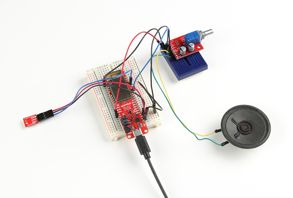
For the following example, you will need the following connection as shown in the Fritzing diagram. The Fritzing diagram connects the input from the microphone to the left analog output. Depending on your setup, you could connect the output to two speakers instead of one. In this case, you would also connect the right analog output (i.e. pin "13" to "RIGHT IN") to the amplifier and add a second speaker (RIGHT OUT and GND) to the setup.
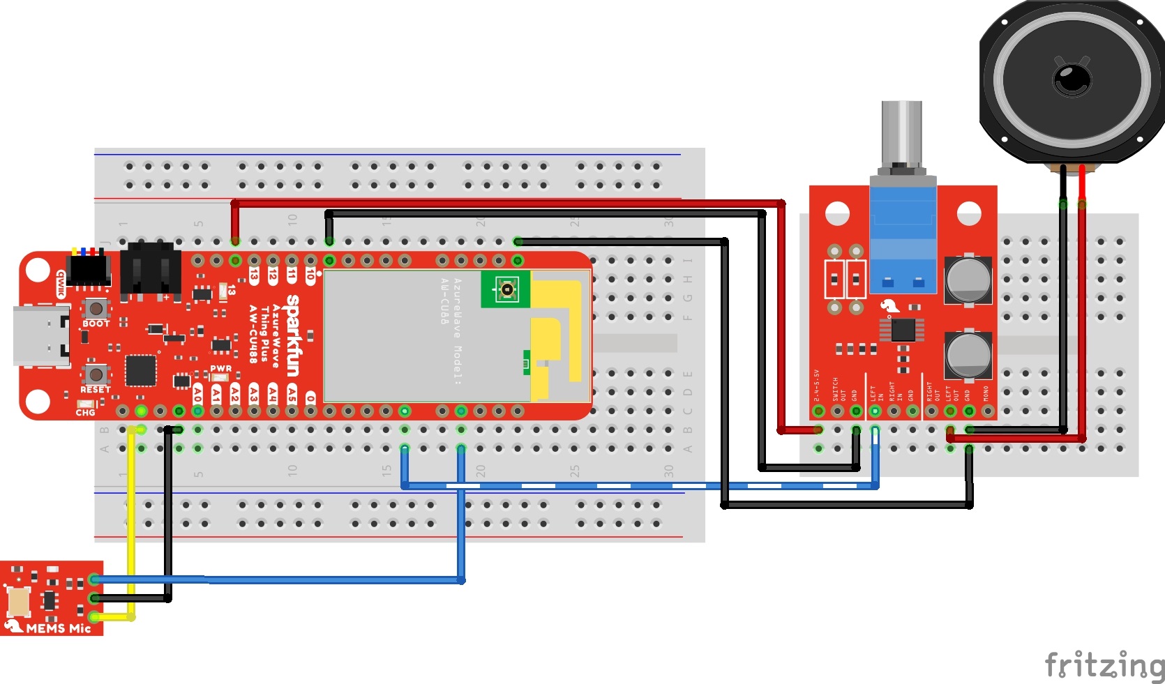
If you have not already, solder headers to the AzureWave Thing Plus (AW-CU488), MEMs microphone, and Noisy Cricket. As explained in the previous section, make sure to carefully remove any flux residue from the boards so that liquid is not trapped in the microphone or AW-CU488 module. Then strip two wires and solder the wire ends to the speaker tabs. Of course, you could solder the pins on the M/M jumper wire to the speaker tab as well without needing to strip the wires as well.

Example Code
Let's upload the sketch to read the input from a microphone and output the signal to one speaker. From the menu, select the following: File > Examples > Examples for AW_CU488 Thing Plus (RTL8721DM) | AmebaAudioCodec > BasicInputOutput.
Or you can copy and paste the following code in the Arduino IDE. Select the correct board definition from the menu (in this case, Tools > Boards > AW-CU488 Thing Plus (RTL8721DM)). Then select the correct COM port that the board enumerated to (in this case, it was COM15). Hit upload button.
language:c
//int analog_pin = A0;  //<=== Add this line before including Audio Codec library if you are using the potiometer and  not using the value A0

#include "AudioCodec.h"

#define SAMPLECOUNT 512

int16_t buffer[SAMPLECOUNT] = {0};
unsigned int vol = 1024;

void setup() {
    Codec.setSampleRate(16000);
    Codec.begin(TRUE, TRUE);
}

void loop() {
    // if received data is avaliable and transmit data buffer is avaliable for write
    if(Codec.writeAvaliable() && Codec.readAvaliable()) {
        Codec.readDataPage(buffer, SAMPLECOUNT);    // read latest received data from buffer
        Codec.writeDataPage(buffer, SAMPLECOUNT);   // write latest data into transmit data buffer
    }
    //vol = analogRead(A0);// commented out so we do not need to connect a potentiometer
    vol = 750; // adjust this value between 0 to 1024
    vol = map(vol, 0, 1024, 0, 100);
    Codec.setOutputVolume(vol, vol);
}
Once uploaded, try blowing some air across the microphone or lightly tapping the microphone on the table. You should hear the same sound but louder on the output speaker. You will notice a small delay on the output as the sound is read in from the microphone and written out to the speakers.
Example 5: Qwiic Micro OLED
Required Materials
To follow along with this part of the tutorial, you will need the following materials. You may not need everything though depending on what you have. Add it to your cart, read through the guide, and adjust the cart as necessary.
Hardware Hookup
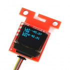
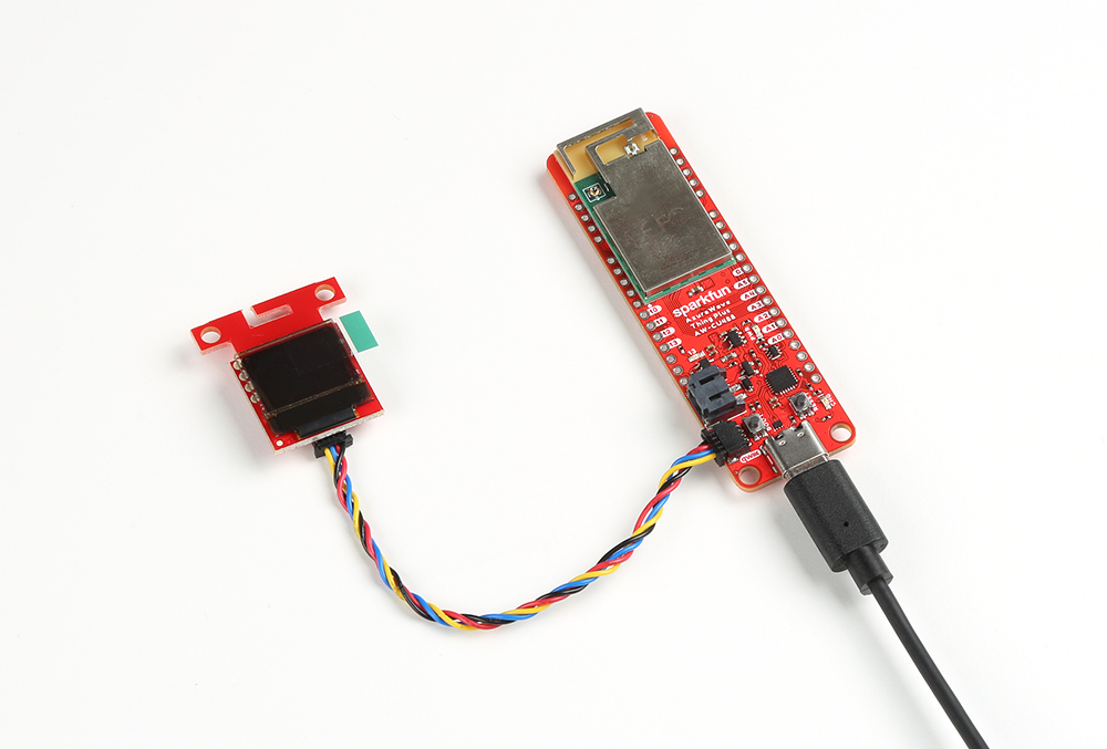
To connect the Qwiic Micro OLED, simply insert a Qwiic cable between the display and the AzureWave Thing Plus (AW-CU488). Then connect a USB C cable between the AzureWave Thing Plus (AW-CU488) and your computer's COM port.
Installing The Arduino Library
Note: This example assumes you are using the latest version of the Arduino IDE on your desktop. If this is your first time using Arduino, please review our tutorial on installing the Arduino IDE. If you have not previously installed an Arduino library, please check out our installation guide.
First, you'll need to download and install the SparkFun Micro OLED library. You can install this library automatically in the Arduino IDE's Library Manager by searching for "Micro OLED Breakout". Or you can manually download it from the GitHub repository. Also, make sure to download the Qwiic example sketches, which we will be reviewing in this tutorial.
Arduino Code | Example 10: MultiDemo v13
Let's upload the sketch to display graphics and characters on the Qwiic Micro OLED. From the menu, select the following: File > Examples > Examples from Custom Libraries | SparkFun Micro OLED Breakout > Example 10 MultiDemo_v13.
Or you can copy and paste the following code in the Arduino IDE. Select the correct board definition from the menu (in this case, Tools > Boards > AW-CU488 Thing Plus (RTL8721DM)). Then select the correct COM port that the board enumerated to (in this case, it was COM21). Hit upload button.
language:c
/*
  SFE_MicroOLED Library Demo
  Paul Clark @ SparkFun Electronics
  Original Creation Date: December 11th, 2020

  This sketch uses the MicroOLED library to show all the functionality built into the library
  using the begin function defined in version v1.3 of the library - which allows different
  TwoWire ports and custom I2C addresses to be used.

  If you are using the standard Micro OLED display, its I2C address will be 0x3D or 0x3C
  depending on how you have the D/C or ADDR jumper configured.

  Hardware Connections:
    This example assumes you are using Qwiic. See the SPI examples for
    a detailed breakdown of connection info.

  Want to support open source hardware? Buy a board from SparkFun!
  https://www.sparkfun.com/products/13003
  https://www.sparkfun.com/products/14532

  This code is beerware; if you see me (or any other SparkFun employee) at the
  local, and you've found our code helpful, please buy us a round!

  Distributed as-is; no warranty is given.
*/

#include <Wire.h>
#include <SFE_MicroOLED.h> //Click here to get the library: http://librarymanager/All#SparkFun_Micro_OLED

#define PIN_RESET 9

/*
// This is the old way of instantiating oled. You can still do it this way if you want to.
#define DC_JUMPER 1
MicroOLED oled(PIN_RESET, DC_JUMPER); // I2C declaration
*/

// From version v1.3, we can also instantiate oled like this (but only for I2C)
MicroOLED oled(PIN_RESET); // The TwoWire I2C port is passed to .begin instead

void setup()
{
  delay(100);
  Wire.begin(); // <-- Change this to (e.g.) Qwiic.begin(); as required
  //Wire.setClock(400000); // Uncomment this line to increase the I2C bus speed to 400kHz


/*
  // This is the old way of initializing the OLED.
  // You can still do it this way if you want to - but only
  // if you instantiated oled using: MicroOLED oled(PIN_RESET, DC_JUMPER)
  oled.begin();    // Initialize the OLED
*/


  // This is the new way of initializing the OLED.
  // We can pass a different I2C address and TwoWire port
  oled.begin(0x3D, Wire);    // Initialize the OLED


/*
  // This is the new way of initializing the OLED.
  // We can pass a different I2C address and TwoWire port
  oled.begin(0x3C, Qwiic);    // Initialize the OLED
*/


  oled.clear(ALL); // Clear the display's internal memory
  oled.display();  // Display what's in the buffer (splashscreen)

  delay(1000); // Delay 1000 ms

  oled.clear(PAGE); // Clear the buffer.

  randomSeed(analogRead(A0) + analogRead(A1));
}

void pixelExample()
{
  printTitle("Pixels", 1);

  for (int i = 0; i < 512; i++)
  {
    oled.pixel(random(oled.getLCDWidth()), random(oled.getLCDHeight()));
    oled.display();
  }
}

void lineExample()
{
  int middleX = oled.getLCDWidth() / 2;
  int middleY = oled.getLCDHeight() / 2;
  int xEnd, yEnd;
  int lineWidth = min(middleX, middleY);

  printTitle("Lines!", 1);

  for (int i = 0; i < 3; i++)
  {
    for (int deg = 0; deg < 360; deg += 15)
    {
      xEnd = lineWidth * cos(deg * PI / 180.0);
      yEnd = lineWidth * sin(deg * PI / 180.0);

      oled.line(middleX, middleY, middleX + xEnd, middleY + yEnd);
      oled.display();
      delay(10);
    }
    for (int deg = 0; deg < 360; deg += 15)
    {
      xEnd = lineWidth * cos(deg * PI / 180.0);
      yEnd = lineWidth * sin(deg * PI / 180.0);

      oled.line(middleX, middleY, middleX + xEnd, middleY + yEnd, BLACK, NORM);
      oled.display();
      delay(10);
    }
  }
}

void shapeExample()
{
  printTitle("Shapes!", 0);

  // Silly pong demo. It takes a lot of work to fake pong...
  int paddleW = 3;  // Paddle width
  int paddleH = 15; // Paddle height
  // Paddle 0 (left) position coordinates
  int paddle0_Y = (oled.getLCDHeight() / 2) - (paddleH / 2);
  int paddle0_X = 2;
  // Paddle 1 (right) position coordinates
  int paddle1_Y = (oled.getLCDHeight() / 2) - (paddleH / 2);
  int paddle1_X = oled.getLCDWidth() - 3 - paddleW;
  int ball_rad = 2; // Ball radius
  // Ball position coordinates
  int ball_X = paddle0_X + paddleW + ball_rad;
  int ball_Y = random(1 + ball_rad, oled.getLCDHeight() - ball_rad); //paddle0_Y + ball_rad;
  int ballVelocityX = 1;                                             // Ball left/right velocity
  int ballVelocityY = 1;                                             // Ball up/down velocity
  int paddle0Velocity = -1;                                          // Paddle 0 velocity
  int paddle1Velocity = 1;                                           // Paddle 1 velocity

  //while(ball_X >= paddle0_X + paddleW - 1)
  while ((ball_X - ball_rad > 1) &&
         (ball_X + ball_rad < oled.getLCDWidth() - 2))
  {
    // Increment ball's position
    ball_X += ballVelocityX;
    ball_Y += ballVelocityY;
    // Check if the ball is colliding with the left paddle
    if (ball_X - ball_rad < paddle0_X + paddleW)
    {
      // Check if ball is within paddle's height
      if ((ball_Y > paddle0_Y) && (ball_Y < paddle0_Y + paddleH))
      {
        ball_X++;                       // Move ball over one to the right
        ballVelocityX = -ballVelocityX; // Change velocity
      }
    }
    // Check if the ball hit the right paddle
    if (ball_X + ball_rad > paddle1_X)
    {
      // Check if ball is within paddle's height
      if ((ball_Y > paddle1_Y) && (ball_Y < paddle1_Y + paddleH))
      {
        ball_X--;                       // Move ball over one to the left
        ballVelocityX = -ballVelocityX; // change velocity
      }
    }
    // Check if the ball hit the top or bottom
    if ((ball_Y <= ball_rad) || (ball_Y >= (oled.getLCDHeight() - ball_rad - 1)))
    {
      // Change up/down velocity direction
      ballVelocityY = -ballVelocityY;
    }
    // Move the paddles up and down
    paddle0_Y += paddle0Velocity;
    paddle1_Y += paddle1Velocity;
    // Change paddle 0's direction if it hit top/bottom
    if ((paddle0_Y <= 1) || (paddle0_Y > oled.getLCDHeight() - 2 - paddleH))
    {
      paddle0Velocity = -paddle0Velocity;
    }
    // Change paddle 1's direction if it hit top/bottom
    if ((paddle1_Y <= 1) || (paddle1_Y > oled.getLCDHeight() - 2 - paddleH))
    {
      paddle1Velocity = -paddle1Velocity;
    }

    // Draw the Pong Field
    oled.clear(PAGE); // Clear the page
    // Draw an outline of the screen:
    oled.rect(0, 0, oled.getLCDWidth() - 1, oled.getLCDHeight());
    // Draw the center line
    oled.rectFill(oled.getLCDWidth() / 2 - 1, 0, 2, oled.getLCDHeight());
    // Draw the Paddles:
    oled.rectFill(paddle0_X, paddle0_Y, paddleW, paddleH);
    oled.rectFill(paddle1_X, paddle1_Y, paddleW, paddleH);
    // Draw the ball:
    oled.circle(ball_X, ball_Y, ball_rad);
    // Actually draw everything on the screen:
    oled.display();
    delay(25); // Delay for visibility
  }
  delay(1000);
}

void textExamples()
{
  printTitle("Text!", 1);

  // Demonstrate font 0. 5x8 font
  oled.clear(PAGE);     // Clear the screen
  oled.setFontType(0);  // Set font to type 0
  oled.setCursor(0, 0); // Set cursor to top-left
  // There are 255 possible characters in the font 0 type.
  // Lets run through all of them and print them out!
  for (int i = 0; i <= 255; i++)
  {
    // You can write byte values and they'll be mapped to
    // their ASCII equivalent character.
    oled.write(i);  // Write a byte out as a character
    oled.display(); // Draw on the screen
    delay(10);      // Wait 10ms
    // We can only display 60 font 0 characters at a time.
    // Every 60 characters, pause for a moment. Then clear
    // the page and start over.
    if ((i % 60 == 0) && (i != 0))
    {
      delay(500);           // Delay 500 ms
      oled.clear(PAGE);     // Clear the page
      oled.setCursor(0, 0); // Set cursor to top-left
    }
  }
  delay(500); // Wait 500ms before next example

  // Demonstrate font 1. 8x16. Let's use the print function
  // to display every character defined in this font.
  oled.setFontType(1);  // Set font to type 1
  oled.clear(PAGE);     // Clear the page
  oled.setCursor(0, 0); // Set cursor to top-left
  // Print can be used to print a string to the screen:
  oled.print(" !\"#$%&'()*+,-./01234");
  oled.display(); // Refresh the display
  delay(1000);    // Delay a second and repeat
  oled.clear(PAGE);
  oled.setCursor(0, 0);
  oled.print("56789:;<=>?@ABCDEFGHI");
  oled.display();
  delay(1000);
  oled.clear(PAGE);
  oled.setCursor(0, 0);
  oled.print("JKLMNOPQRSTUVWXYZ[\\]^");
  oled.display();
  delay(1000);
  oled.clear(PAGE);
  oled.setCursor(0, 0);
  oled.print("_`abcdefghijklmnopqrs");
  oled.display();
  delay(1000);
  oled.clear(PAGE);
  oled.setCursor(0, 0);
  oled.print("tuvwxyz{|}~");
  oled.display();
  delay(1000);

  // Demonstrate font 2. 10x16. Only numbers and '.' are defined.
  // This font looks like 7-segment displays.
  // Lets use this big-ish font to display readings from the
  // analog pins.
  for (int i = 0; i < 25; i++)
  {
    oled.clear(PAGE);           // Clear the display
    oled.setCursor(0, 0);       // Set cursor to top-left
    oled.setFontType(0);        // Smallest font
    oled.print("A0: ");         // Print "A0"
    oled.setFontType(2);        // 7-segment font
    oled.print(analogRead(A0)); // Print a0 reading
    oled.setCursor(0, 16);      // Set cursor to top-middle-left
    oled.setFontType(0);        // Repeat
    oled.print("A1: ");
    oled.setFontType(2);
    oled.print(analogRead(A1));
    oled.setCursor(0, 32);
    oled.setFontType(0);
    oled.print("A2: ");
    oled.setFontType(2);
    oled.print(analogRead(A2));
    oled.display();
    delay(100);
  }

  // Demonstrate font 3. 12x48. Stopwatch demo.
  oled.setFontType(3); // Use the biggest font
  int ms = 0;
  int s = 0;
  while (s <= 5)
  {
    oled.clear(PAGE);     // Clear the display
    oled.setCursor(0, 0); // Set cursor to top-left
    if (s < 10)
      oled.print("00"); // Print "00" if s is 1 digit
    else if (s < 100)
      oled.print("0"); // Print "0" if s is 2 digits
    oled.print(s);     // Print s's value
    oled.print(":");   // Print ":"
    oled.print(ms);    // Print ms value
    oled.display();    // Draw on the screen
    ms++;              // Increment ms
    if (ms >= 10)      // If ms is >= 10
    {
      ms = 0; // Set ms back to 0
      s++;    // and increment s
    }
  }
}

void loop()
{
  //pixelExample();  // Run the pixel example function
  lineExample();  // Then the line example function
  shapeExample(); // Then the shape example
  textExamples(); // Finally the text example
}

// Center and print a small title
// This function is quick and dirty. Only works for titles one
// line long.
void printTitle(String title, int font)
{
  int middleX = oled.getLCDWidth() / 2;
  int middleY = oled.getLCDHeight() / 2;

  oled.clear(PAGE);
  oled.setFontType(font);
  // Try to set the cursor in the middle of the screen
  oled.setCursor(middleX - (oled.getFontWidth() * (title.length() / 2)),
                 middleY - (oled.getFontHeight() / 2));
  // Print the title:
  oled.print(title);
  oled.display();
  delay(1500);
  oled.clear(PAGE);
}
Once uploaded, check out the Qwiic Micro OLED. You should see the SparkFun logo followed by the demo! Try adding a sensor, modifying the code, and displaying the sensor values on the screen.
More Examples!
Of course, this only skims the surface of what the SparkFun AzureWave Thing Plus (AW-CU488) can do. There are a handful of examples from the board support package that were not highlighted in this tutorial and are being ported by our friends at Realtek with the AW-CU488 module. From the menu, try opening the other examples listed for the board: File > Examples > Examples for AW_CU488 Thing Plus (RTL8721DM).
Or try adding another Qwiic-enabled device or a breakout board to your next project!
Troubleshooting
If you need technical assistance and more information on a product that is not working as you expected, we recommend heading on over to the SparkFun Technical Assistance page for some initial troubleshooting.
If you don't find what you need there, the Realtek Forums or our SparkFun Forums are a great place to find and ask for help.
Manual Upload Mode
Having problems uploading code with the auto upload mode? Try uploading code manually. Hit the upload button in the Arduino IDE. In the debug window, you should see something similar. As the Arduino IDE starts outputting the numbers.
language:bash
Please enter the upload mode manually(wait 5s)
    05
    04
    03
    02
    01
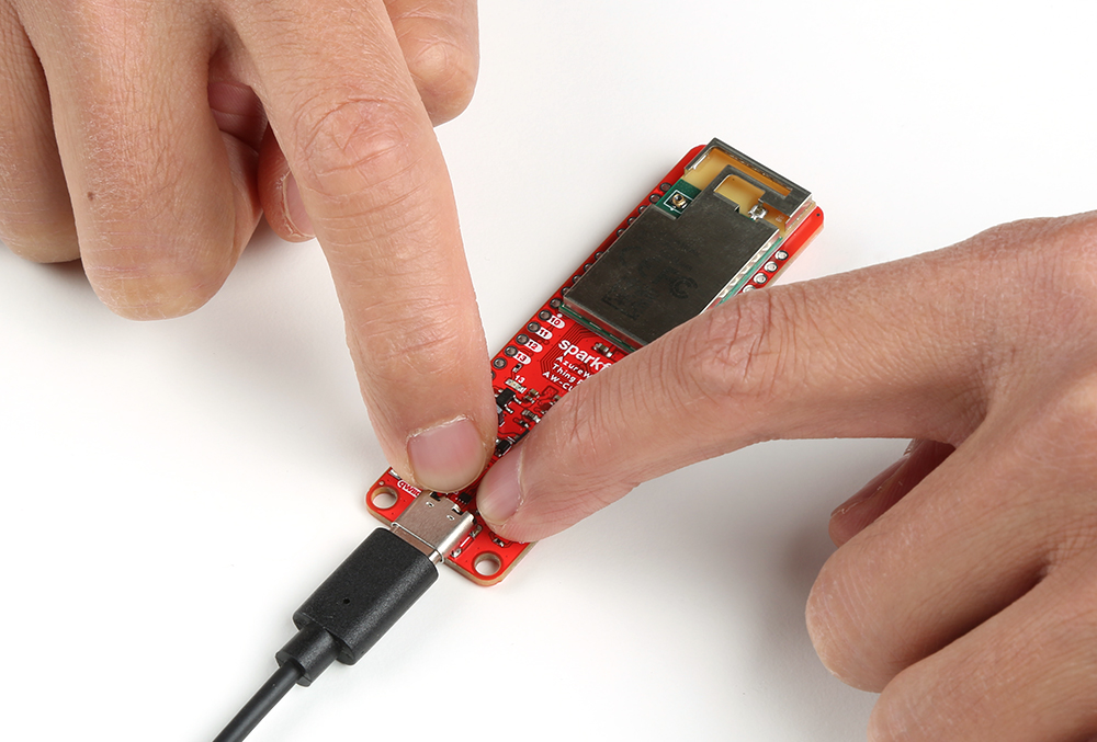
Press down on the BOOT button. While holding down the BOOT button, press the RESET Button momentarily. Keep holding the BOOT button for a moment before lifting your finger off the button.
 |
 |
|
 |
| BOOT Button | BOOT and RESET | Keep Holding Down BOOT | Release BOOT |
If all goes well, you should have a successful upload with the following message.
language:bash
Please enter the upload mode manually(wait 5s)
    05
    04
    03
    02
    01
Uploading..................
    Upload Image done.
All images are sent successfully!
Resources and Going Further
Now that you've successfully got your SparkFun AzureWave Thing Plus (AW-CU488) up and running, it's time to incorporate it into your own project! For more information, check out the resources below:
- Schematic (PDF)
- Eagle Files (ZIP)
- Board Dimensions (PNG)
- Fritzing Part (FZPZ)
- Graphical Datasheet (PDF)
- Datasheet
- Qwiic Info Page
- Compare Thing Plus Boards
- Board Support Files
- GitHub Hardware Repo
- SFE Product Showcase
Need some inspiration for your next project? Check out some of these related to wireless tutorials.
Blynk Board Project Guide
SparkFun Arduino ProtoShield Hookup Guide
MicroMod WiFi Function Board - ESP32 Hookup Guide
Monitor Sensor Data from Anywhere
Or check out some of these related to audio tutorials.