BadgerHack: Sensor Add-On Kit
Contributors:
 Sarah Al-Mutlaq
Sarah Al-Mutlaq 
Hardware Hook-up
There is a little bit of soldering, so if you need a quick refresher on that I suggest taking a look at our soldering tutorial.
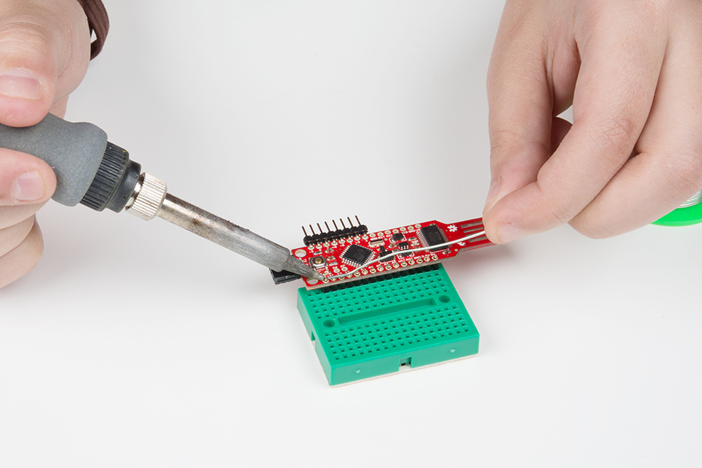
To begin, snap off 15 pins from the break-away headers, and solder them to the through-holes on the side opposite the LED array of the BadgerStick.
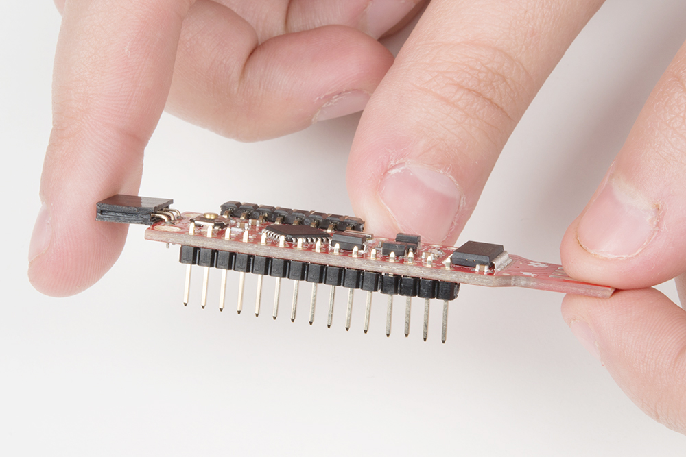
You can place the headers in the breadboard to help keep them in place as you solder.
The rest of the setup will be using the breadboard and the jumper wires.
Start by sticking the headers you just soldered to your stick at a corner of your breadboard.
Now we will connect the sensors as follows:
| Component Pin | Badger/Redstick Pin | |||
|---|---|---|---|---|
| Soil Moisture Sensor VCC | VCC | |||
| Soil Moisture Sensor GND | GND | |||
| Soil Moisture Sensor SIG | A0 | |||
| Temperature Sensor left | GND | |||
| Temperature Sensor middle | A4 | |||
| Temperature Sensor right | VCC | |||
* Pins not listed are not used.
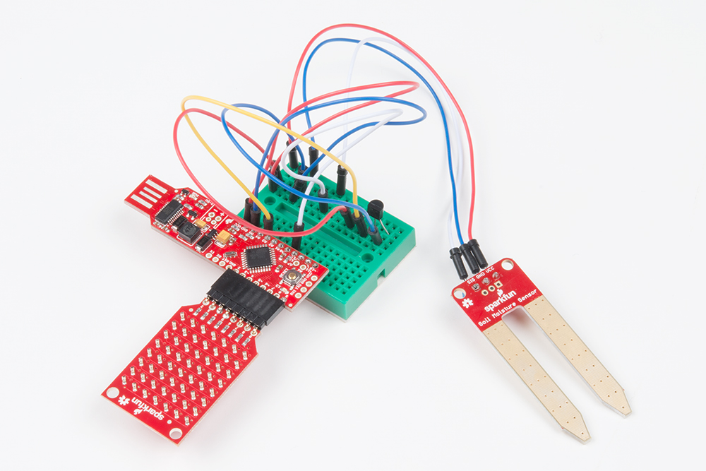
Here is a picture layout of how to connect everything up

Fritzing diagram of a RedStick hookup (GND and VCC slightly different on a BadgerStick).
IMPORTANT: You will need to power your Badgerstick/Redstick through its USB port or a USB extension cable, so that the analog sensors are getting a known voltage. You can cut the battery pack off, you can leave the battery pack attached but turned off, or you can power it through the battery pack. Just know that your temp reading will become less accurate the more your battery drains.
With everything hooked up, it's time to upload some code.