BadgerHack: Synth Add-On Kit
 Nick Poole
Hardware Hookup
Badger on a Breadboard
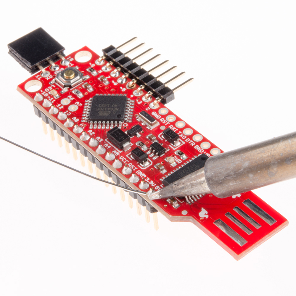
The BadgerStick is a great form factor for breadboard prototyping. If you have a fresh BadgerStick or RedStick out of the box, you can add male breakaway headers to both sides and sink it right into the breadboard over the gap. Make sure to add headers to pins A0 through VCC and pins 2 through 9. The holes on the BadgerStick are staggered so that the headers will stay in place while you solder them, simply snap off two strips of 8 headers and press them into place before securing them with a series of solder joints.
I'm going to assume for the purposes of this tutorial, however, that you've already assembled the BadgerStick into an interactive badge and therefore already have female right-angle headers installed on pins 2 through 9. You can use male right angle headers to mate your BadgerStick/RedStick to the breadboard instead of having to desolder those headers. Alternatively, you can desolder the headers and replace them with straight male headers.
A Jungle of Jumper Wires
A pack of jumper wires on our site contains 30 jumpers. Today, we're going to be using every single one of those. Start by placing all of your parts on the breadboard like this:
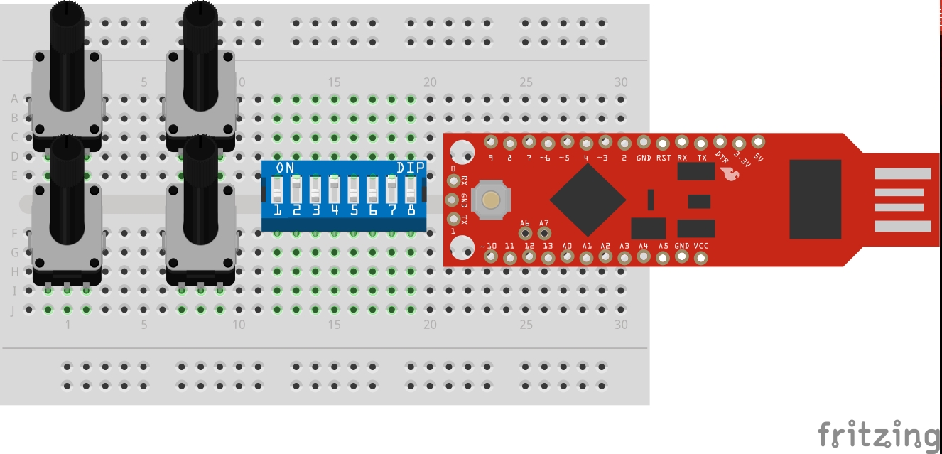
The potentiometers in the above picture don't look like the ones I suggested in my wishlist, but they'll work the same way. Now, with the jumper wires, begin making the connections listed here:
| Connect this: | To This: | |||
|---|---|---|---|---|
| DIP Switch Pins 1-8 | BadgerStick Pins 2-9 | |||
| All Potentiometers' Pin 1 | GND Rail of Breadboard | |||
| All Potentiometers' Pin 3 | VCC Rail of Breadboard | |||
| All Potentiometers' Pin 2 | BadgerStick A0-A3 | |||
| Speaker Pin 1 | BadgerStick A4 | |||
| Speaker Pin 2 | BadgerStick A5 | |||
| GND Rail of Breadboard | BadgerStick GND | |||
| VCC Rail of Breadboard | BadgerStick VCC | |||
Once these connections have been made, your breadboard should look more or less like the image below. I did use a larger breadboard just so that there was enough room to clearly illustrate each jumper connection:
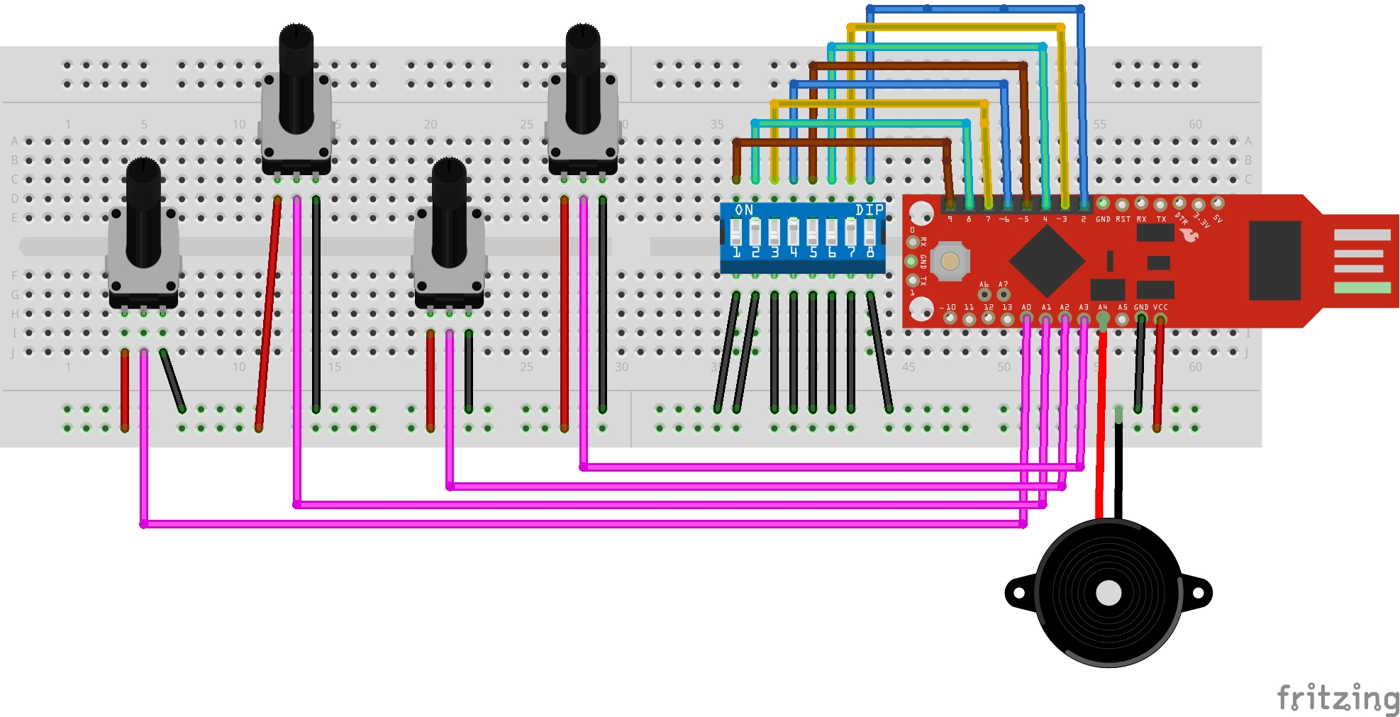
That wraps up the hardware portion of this hack, let's go take a look at the code!