Bark Back Interactive Pet Monitor
Contributors:
 jenfoxbot
jenfoxbot 
Hardware Hookup
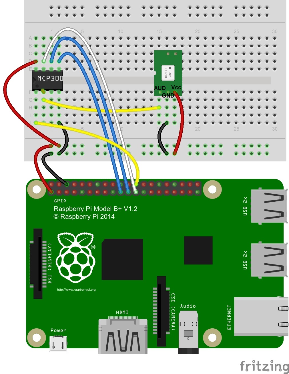
Hooking the Pi up to the other hardware. Click on the wiring diagram for a closer look.
Here's the Raspberry Pi 2 (and 3) Model B pinout diagram:
1. Connect the MCP3002 to the Raspberry Pi.
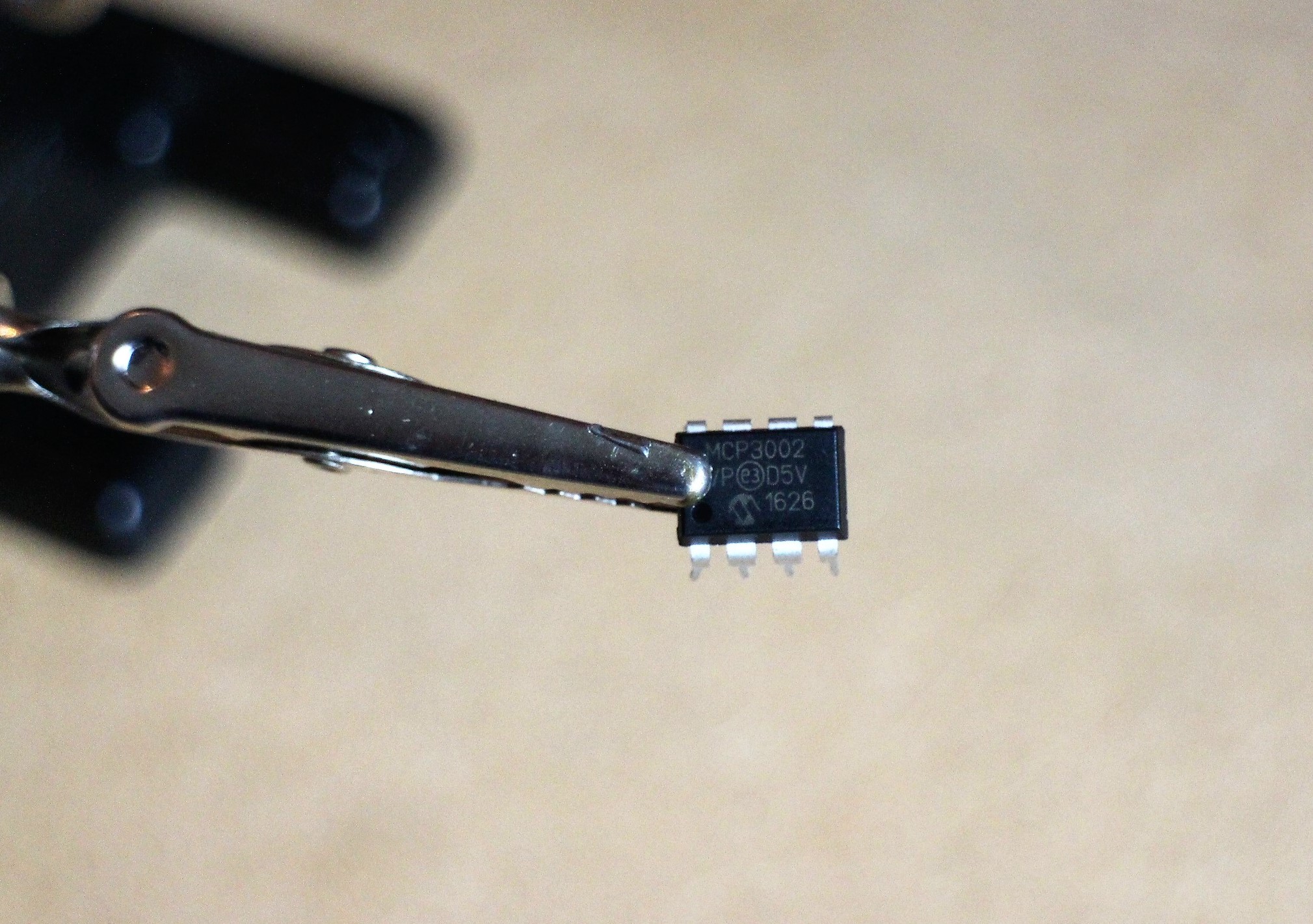
Close-up of the MCP3002
There are four SPI pins for SPI communication: Serial Clock ("SCL"), Master Input Slave Output ("MISO"), Master Output Slave Input ("MOSI") and Chip Select ("CS"). These pins correspond to Raspberry Pi GPIO pin 11 (SCLK), GPIO pin 9 (MISO), GPIO pin 10 (MOSI) and GPIO pin 8 (CE0), respectively.
Here's the MCP302 pinout diagram:
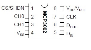
Make the following connections with MCP3002 pins:
- Connect pin 1 to Raspberry Pi GPIO pin 8 (CE0)
- Connect pin 2 to the analog output of the MEMS Microphone breakout board
- Connect pin 4 to GND
- Connect pin 5 to Raspberry Pi GPIO pin 10 (MOSI)
- Connect pin 6 to Raspberry Pi GPIO pin 9 (MISO)
- Connect pin 7 to Raspberry Pi GPIO pin 11 (SCLK)
- Connect pin 8 to Raspberry Pi 3.3V out
2. Solder wires to the MEMS Microphone breakout board. Connect to MCP3002 and Raspberry Pi.
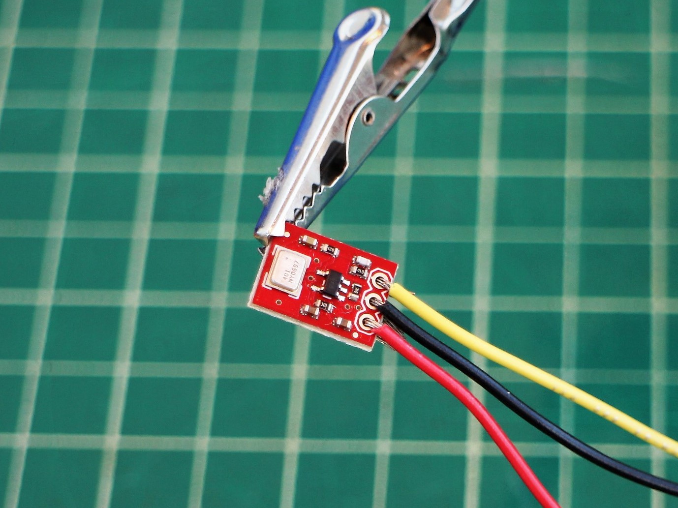
- Connect Vcc to Raspberry Pi 3.3V.
- Connect GND to Raspberry Pi GND
- Connect AUD to MCP3002 Pin 2