Basic Servo Control for Beginners
 El Duderino
Direct Servo Control with the Qwiic Joystick
Controlling servos in loops can be good for projects where you just want something moving while powered but what if you want more of a direct ability to control your servo? This project looks to demonstrate how to do just that!
For this project, we'll use the Qwiic Joystick as our input to control two servos on a pan/tilt bracket attached to a RedBoard Qwiic. Make sure to check out the Qwiic Joystick Hookup Guide for more information about the Qwiic Joystick:
Qwiic Joystick Hookup Guide
February 21, 2019
Required Materials
To follow along with this example project you will need the following materials. Depending on what parts you already have, you may want to update your cart accordingly.
Hardware Hookup
The first thing we want to assemble for this project is our pan/tilt bracket with the two sub-micro servos. The assembly guide below gives some basic instructions on how to build the pan/tilt bracket with your servos.
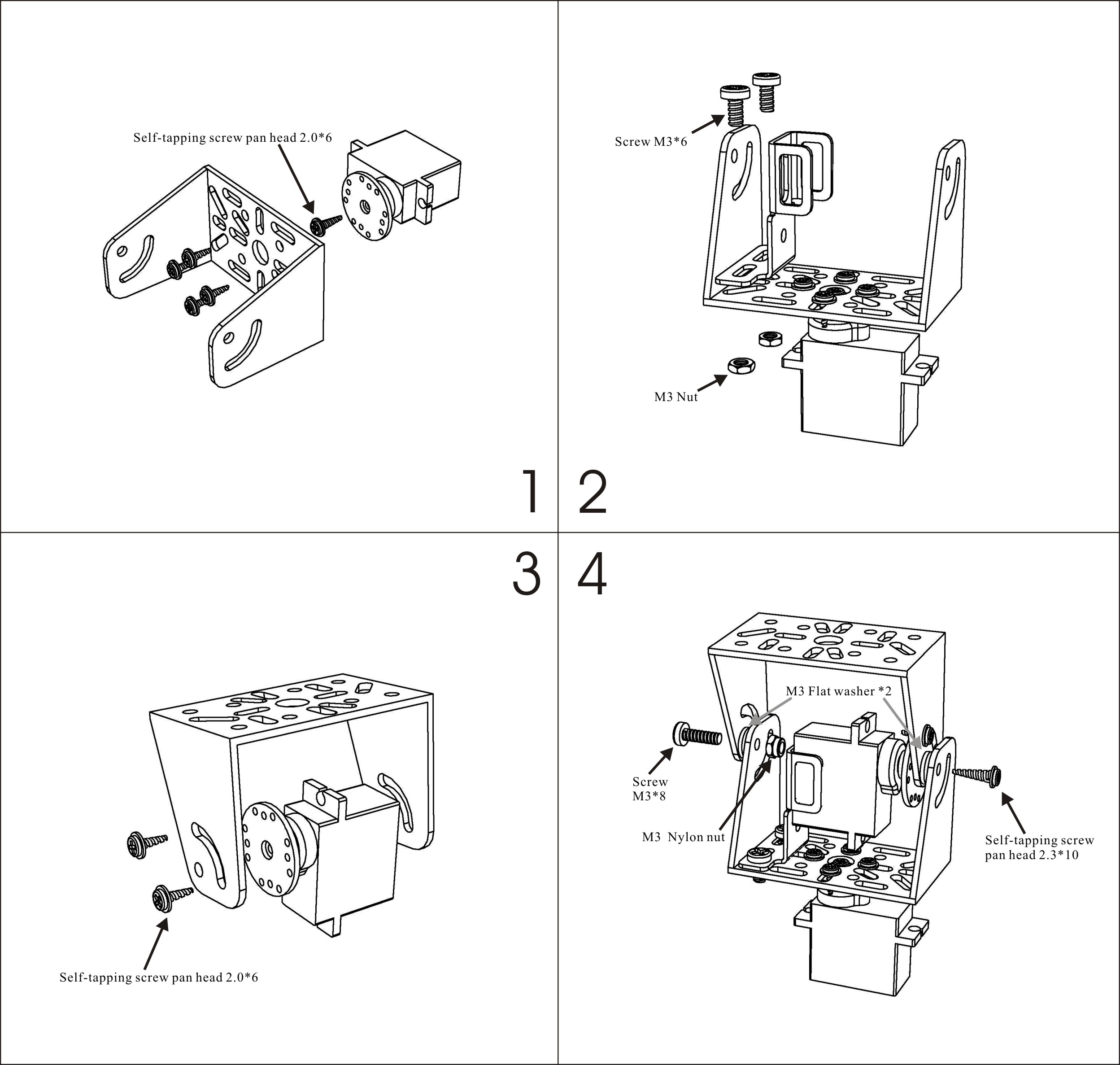
Take care to align the servos properly so you can take advantage of the full range of motion and avoid having to re-seat the servos once everything is wired up.
Depending on the fit, you may need to use three washers for spacing instead of 2 like the guide suggests.
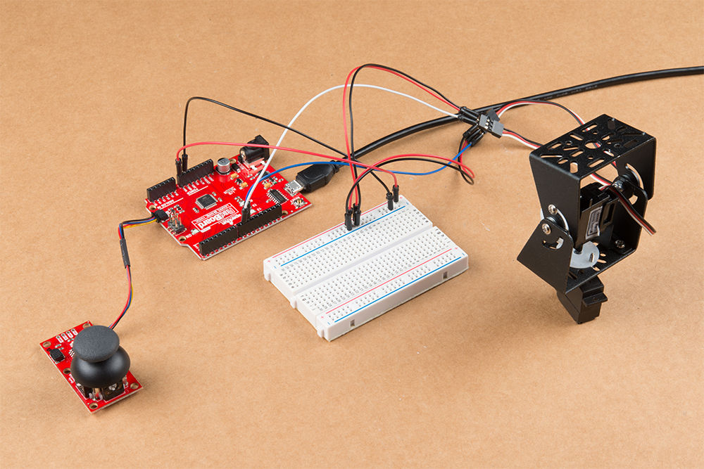
With the pan/tilt bracket assembled, connect the signal wires of the servos to the assigned I/O pins on your RedBoard and connect the Qwiic Joystick to the RedBoard with a Qwiic Cable. The example code uses D9 for the horizontal servo and D10 for the vertical servo by default but you can connect them to other pins if needed by modifying the servoH.attach(9); and servoV.attach(10); functions.
Finally, we need to connect the power supply pins for our servos. Just like with the Arduino Servo Library example from earlier, we are going to use the VIN pin on our RedBoard since the 5V pin can only source up to 250mA and our pan/tilt servos can pull in excess of 350mA with nothing attached to the bracket.
Since we have two servos for our pan/tilt bracket, we will use a breadboard to net the power pins for the servos together.
Connect the power and ground pins of each servo to the "+" and "-' rails of your breadboard and then, with the RedBoard unpowered, connect the VIN and GND pins on your RedBoard to the respective rails on the breadboard as well. Once you have all of the power and ground pins tied together properly, plug in your RedBoard via USB.
Arduino Code
With everything wired up, it is time to upload our code. First, we need to install the Qwiic Joystick Library if it is not installed already. You can manually install it by downloading it from the link above but we recommend installing the library through the Library Manager tool. Simply open that up and search for "SparkFun Qwiic Joystick" and click install. If you've never installed an Arduino library before, our Installing an Arduino Library Tutorial covers the entire process.
Now that the library is installed, go ahead and copy the code below and paste it into a new sketch. Select "Arduino/Genuino Uno" as your board (or if you are using another development board, select that) as well as the "Port" your board is on and upload the code.
language:c
/*
 Example code to control two servos using the SparkFun Qwiic Joystick.
 Code takes the readings of the Vertical (Y) and Horizontal (X) axes of the joystick
 and maps them to values between 0 and 180 degrees.

 Based off of the Arduino "Knob" example:

 Controlling a servo position using a potentiometer (variable resistor)
 by Michal Rinott <http://people.interaction-ivrea.it/m.rinott>

 modified on 8 Nov 2013
 by Scott Fitzgerald
 http://www.arduino.cc/en/Tutorial/Knob
*/

#include <Servo.h>
#include "SparkFun_Qwiic_Joystick_Arduino_Library.h"

JOYSTICK joystick; // create joystick object to send position values


Servo servoH;  // create servo object to control a servo
Servo servoV;

int h;    // variable to read the horizontal values from the Qwiic Joystick
int v;    // variable to read the vertical values from the Qwiic Joystick

void setup() {
  servoH.attach(9); // attaches servo1 on pin 9 to the servo object
  servoV.attach(10);  // attaches servo2 on pin 10 to the servo object
  Serial.begin(9600);
  Serial.println("Qwiic Joystick Servo Control");

  if(joystick.begin() == false)
  {
    Serial.println("Joystick not connected. Check wiring. Freezing...");
    while(1);
  }
}

void loop() {
  h = joystick.getHorizontal();   // reads the value of the Qwiic Joystick's horizontal axis (between 0 & 1023)
  h = map(h, 0, 1023, 0, 160);     // scale it to use it with the servo (value between 0 and 180)
  servoH.write(h);                  // sets the horizontal servo position according to the scaled value
  v = joystick.getVertical(); // reads the value of the Qwiic Joystick's vertical axis (between 0 & 1023)
  v = map(v, 0, 1023, 0, 165);
  servoV.write(v);
  delay(15);    // waits for the servo to get there
  /*Serial.print("X: ");  //uncomment these lines to view the serial print of the x and y axes of the Qwiic Joystick
  Serial.print(joystick.getHorizontal());   //these can be helpful for debugging or identifying any drift on your joystick
  Serial.print("Y: ");
  Serial.print(joystick.getVertical());
  Serial.println();*/
}
Once the code finishes uploading try moving the joystick around. You should see the servo connected to pin 9 react to movements on the horizontal axis and the servo on pin 10 will react to movements on the vertical axis just like the GIF below.
Troubleshooting Tips
Here are some tips if you run into some common pitfalls with this example.
Compilation and Upload Errors
If you end up getting any compilation errors such as avrdude stk500_recv() programmer is not responding or something similar regarding the target device (aka our RedBoard), make sure you have selected the correct Port for your RedBoard as well as the correct board type.
If you see errors similar to SparkFun_Qwiic_Joystick_Arduino_Library.h: No such file or directory, the Qwiic Joystick library was not installed properly. Check to make sure the library is installed and is the latest version using the Arduino Library Manager tool.
Power Issues
Since we are using a breadboard for this example, a common cause of any power issues (e.g. the entire circuit is not turning on when plugged into USB) is a misplaced wire. Check that you have all of your power and ground wires properly connected on your breadboard. A common error is one or more of the wires is backward (i.e. power to ground or vice versa). Verify those are plugged into the right rail on your breadboard and are making a good connection to both the servo and your RedBoard.