BC118 BLE Mate 2 Hookup Guide
Contributors:
 SFUptownMaker
SFUptownMaker 
Hardware Overview
Let's take a look at the BLE Mate 2 board.
Front
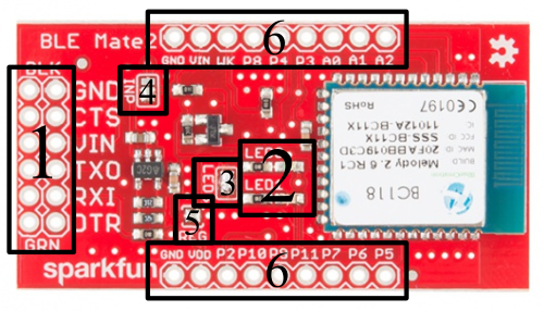
The image above has the major parts of the BLE Mate 2 labeled. We'll start with the front, since it's more interesting. We're just going to apply labels to things here; we'll discuss their full use on the next page.
- 6-pin FTDI Basic compatible serial header - This header has the same pinout as that of an FTDI Basic board; it's meant to connect to a client device such as an Arduino Pro. If you want to connect it to an FTDI Basic board, you'll need to either make or buy a crossover adapter. We've provide two rows of pins to make multiple connections to these pins (e.g. to sniff the signals for troubleshooting) easier.
- LED0 and LED1 - These LEDs display information about the current state of the module. These LEDs reflect the logical state of the module, and a reset of the module may be needed before the settings take effect. More on that later.
- LEDs jumper - this jumper ships closed with solder; clear the jumper to disable the LEDs and save some current for low-power situations.
- INP jumper - this jumper connects the voltage input pin on the 6-pin header to the 3.3V regulator on the BLE Mate 2. It can be cleared to remove the regulator from the circuit and save current.
- REG jumper - clearing this jumper will break the connection between the output of the 3.3V regulator and the supply of the BC118 module.
- GPIO headers - All the pins on the BC118 are broken out to these pins, as are power and ground.
Back
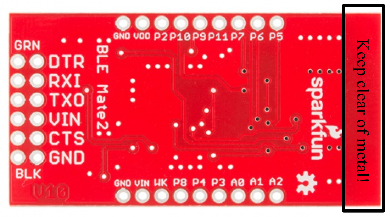
The back is much simpler. You'll note that all the pin labels are present on this side as well.
The one thing that is really worth pointing out from this side is the keepout at the top of the board. You can see that the ground plane only extends so far up the PCB; for best performance, you should try and keep that area free of any metal when embedding the BLE Mate 2 in a project. Failing to do so may result in interference or a loss of signal strength.