Blynk Board Project Guide
 jimblom
 Project 1: Blynk Button, Physical LED
Enough reading, time for blinking/Blynking! Our first project explores one of the most fundamental concepts in electronics and programming: digital input and output. A digital signal has a finite number of states -- in fact, it usually only has two possible conditions: ON (a.k.a. HIGH, 1) or OFF (a.k.a. LOW, 0).
💡Blink – the Electronics "Hello, Word"
As simple as this project may look, blinking an LED is the first step towards a long, fruitful journey of electronics tinkering. You'd be surprised at how many other real-world objects you can manipulate with a simple HIGH/LOW digital signal: you can turn a Relay on or off -- which can, in turn, control power to any household electronics. You can use digital signals to spin motors (or at least drive a motor controller). Or you can quickly pulse a digital signal to produce tones in a buzzer.
Using Blynk's Button widget, we can send a digital signal to the Blynk Board. If we attach that input to the right output on the Blynk board, we can use the HIGH/LOW signal to turn an LED on or off.
Blynk Setup
By now you should already have a Blynk project -- complete with an LED-controlling zeRGBa -- running on your phone. We're going to continue using this project for our experimenting in this guide.
Don't delete the BlynkMe project! We'll continue using the provisioning-provided Blynk project throughout this tutorial. Later, after coming up with a Blynk project of your own, you can create more projects (or continue using this one).
Make sure you keep the Blynk Board QR-Code Card – although it won't supply your account with more energy, it can be used to re-provision the Blynk Board.
Removing Widgets
Since we'll be using the same project throughout, you'll eventually want to make some space for more/bigger widgets. So to begin, let's clear the project out (don't worry, the zeRGBa and LCD are coming back soon!).
To delete widgets from your a Blynk project, follow these steps:
- If your project is still running, stop it by clicking the square stop button in the upper right-hand corner.
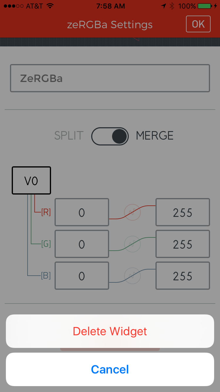
- Tap the zeRGBa widget to open its settings.
- Scroll down to the bottom of the zeRGBa settings and press the red delete button.
- Confirm the deletion -- on iOS click Delete Widget, on an Android hit "OK" on the popup dialog.
Follow the same set of steps to remove the LCD widget from the project.
Adding a Button to Pin 5
Let's start by adding a simple button widget. Here's how:
- Make sure your project is not running -- the upper-right icon should be a triangular play button.
- Touch anywhere in the blank, gray project space. A toolbox should open up on the right side with all of your widgets to choose from.
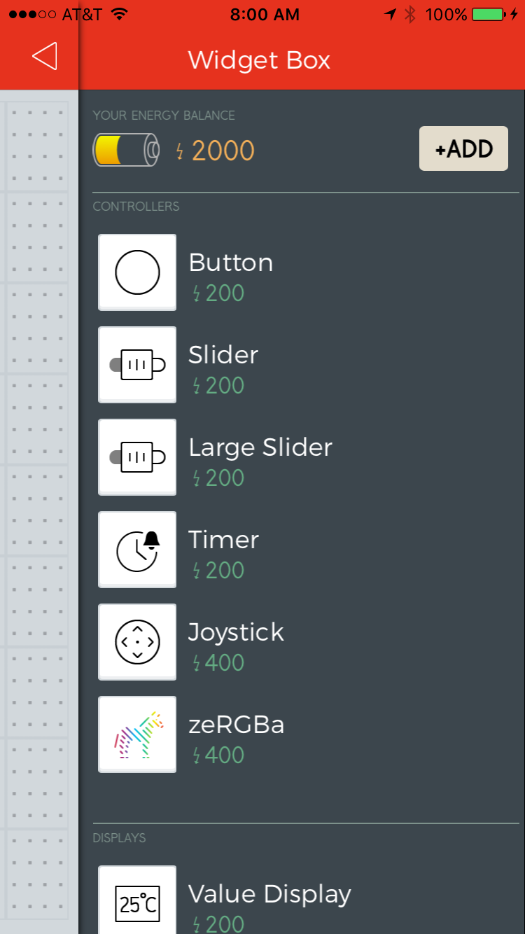
- Select the Button widget by tapping it. You'll find it at the top of the "Controllers" list.
- Tap and hold the button widget to drag it anywhere within the project space. You've got a lot of room to work with right now.
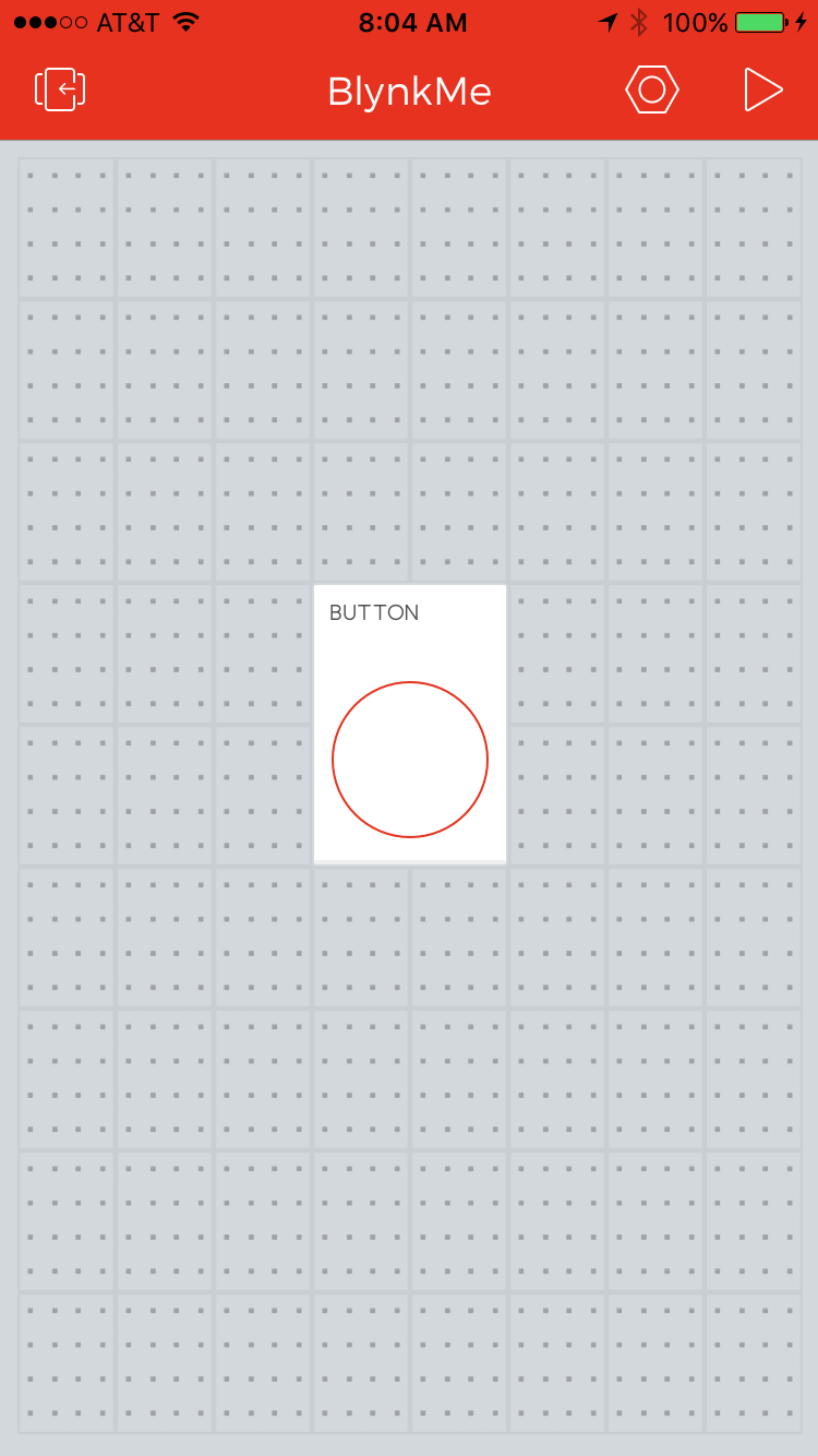
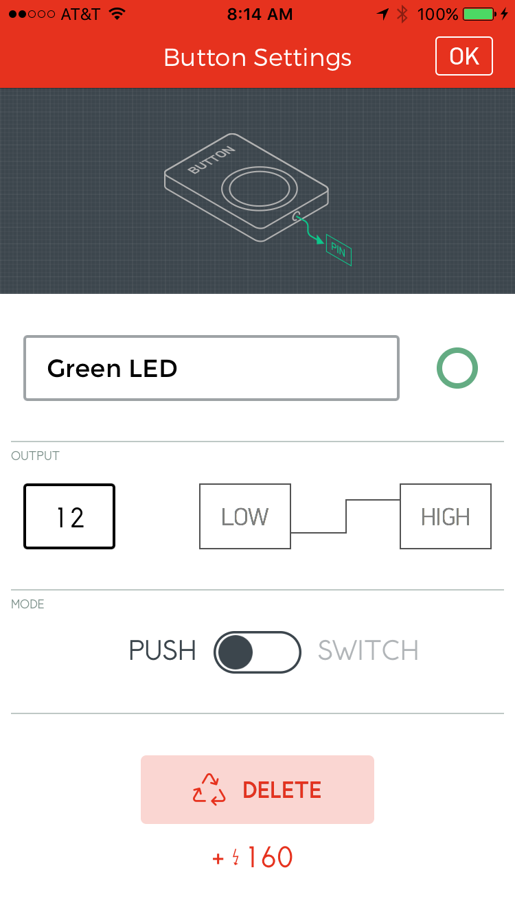
- Touch the Button Widget to bring up the settings page, and modify these values:
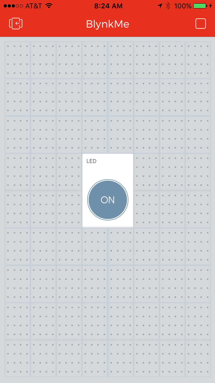
- Name: "LED" – While the widget is a button, we'll be using it to control an LED.
- Output: 5 – in the "Digital" list.
- Color: Click the red circle to change the color of the button. Try blue, since we're toggling a blue LED!
- Mode: Take your pick. Try them both!
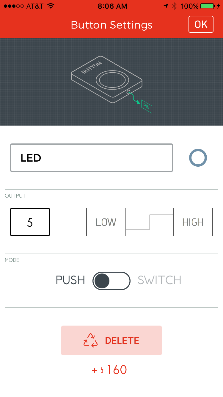
- Confirm the settings.
- If you're using an Android, hit the back arrow in the upper-left corner
- If you're using an iOS device, hit the OK button.
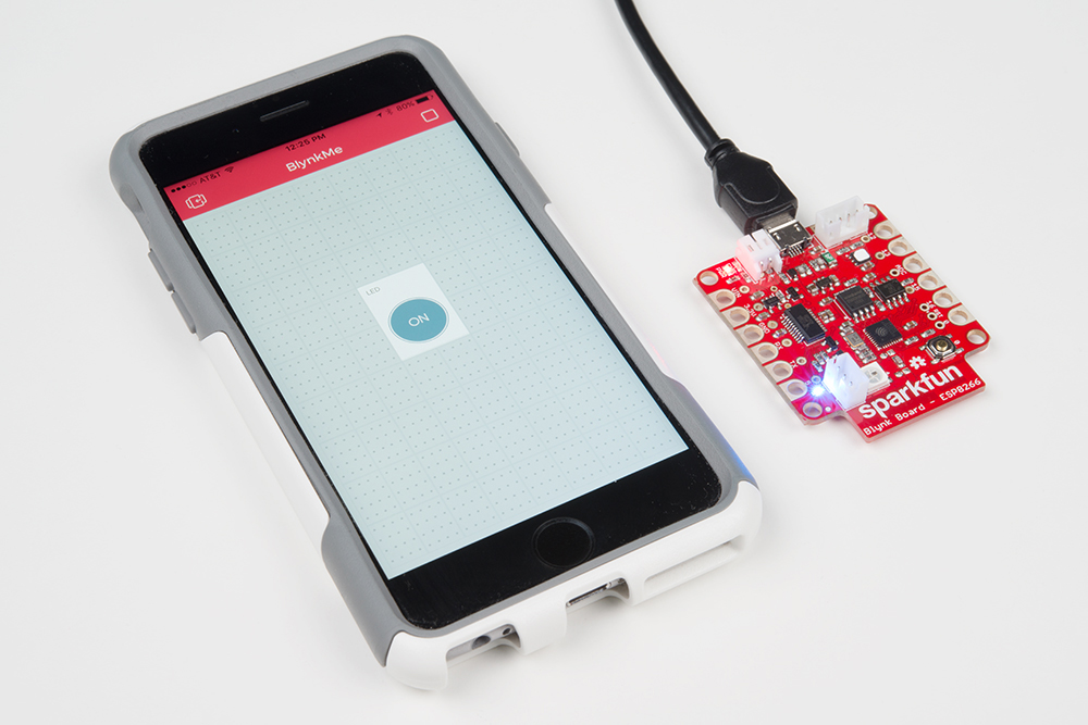
Now that the button is all configured, run the project by tapping the play button in the upper-right corner of the screen.
Blynk Run
Once the project is running, tap your new-blue button widget. When the widget is set to ON, the tiny blue LED should also turn on.
Button: Push vs. Switch
Try switching the button’s mode between push and switch. Whenever you need to make changes to a widget’s settings tap the upper-right stop button, then tap the widget you’d like to configure. Once you’re done configuring, confirm the changes (“OK” button on iOS, upper-left back-arrow on Android), and set the project back to run mode.
If you have the widget set to PUSH, you’ll have to hold the button down to keep the LED on. SWITCH mode allows you to set it and leave it. Give them both a try and see which you prefer.
Going Further: Adding an Offboard LED
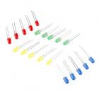
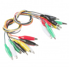
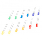
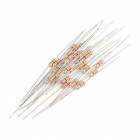
While it's a useful status indicator, that blue LED is so small it's barely visible above the shine of the RGB LED. Combining a couple alligator clip cables, with a 330Ω resistor, and an LED of your choice, you can offboard the Blynk Board's LED control.
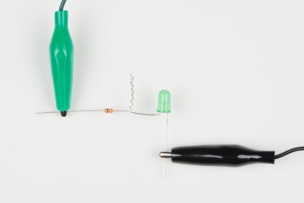
First, locate the LED's positive, anode pin -- you'll be able to identify it by the longer leg.
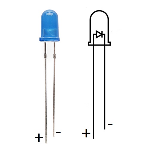
Bend the long leg out 90°, then twist it together with one of the legs of the 330Ω resistor (either end, resistors aren't polarized).

Next grab two alligator clip cables -- one black, the other green (although the color doesn't matter, using black for the ground wire is a nice convention to follow). Clamp one end of the black cable to the LED, and clamp one end of the other cable to the resistor.
Plug the other end of the black cable into the "GND" pin, and the other end of the green cable to the "5" pin.
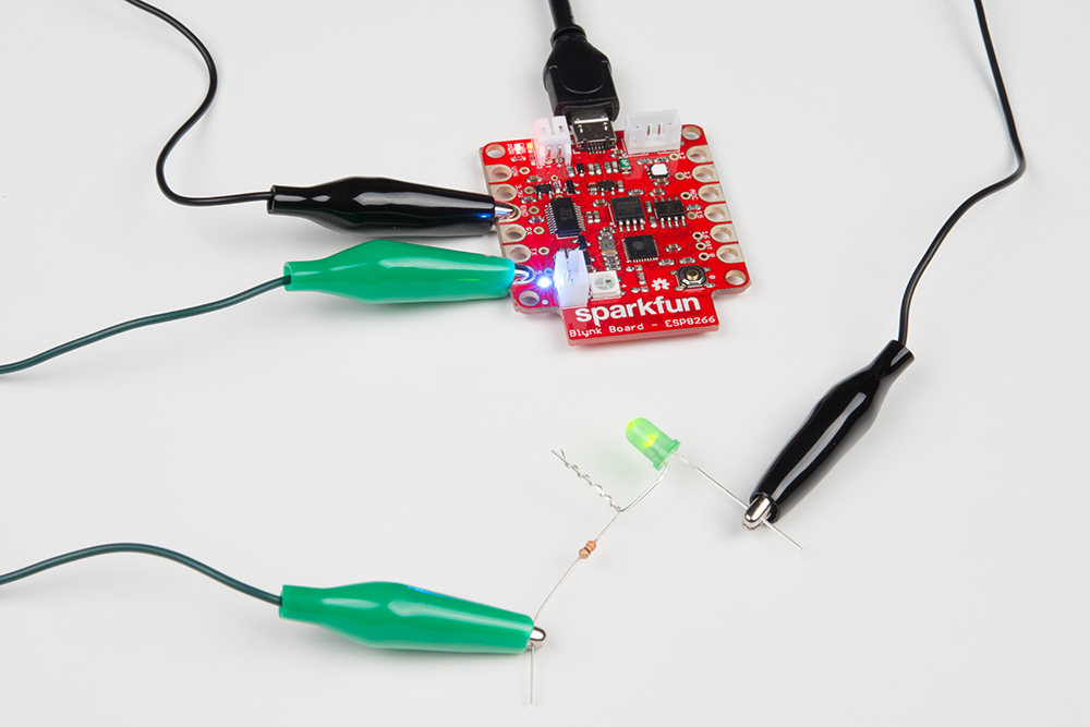
Now flick the Blynk app's LED button again. Not only will the blue LED toggle, but your offboard LED should too! If the LED isn't turning on, try swapping the alligator clip cables around on the LED and resistor legs.
Changing the Digital Pins
Now try driving the offboard LED using pin 12. Move the green alligator clip from the "5" pin to the "12".
You'll also need to either add another button widget, or change the settings of the one you've already laid down.
Feel free to repeat the same experiment on pins 13 and 15! Avoid pins 0 and 16 for now, they'll be used as inputs later in this tutorial.