BMP180 Barometric Pressure Sensor Hookup
This Tutorial is Retired!
This tutorial covers concepts or technologies that are no longer current. It's still here for you to read and enjoy, but may not be as useful as our newest tutorials.
 MikeGrusin
Connecting the Hardware
In this guide, we'll connect the BMP180 to an Arduino microcontroller. If you're using a different microcontroller, don't panic. Many microcontrollers have an I2C interface, and you can use this library, datasheet, and example code to help you write you own code.
Connection Names
The BMP180 Breakout Board breaks out five connections from the IC. We traditionally call these connections "pins" because they come from the pins on the IC, but they are actually holes that you can solder wires or header pins to.
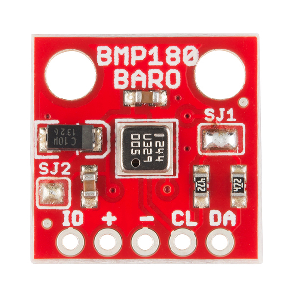
We'll connect four of the five pins on the board to your Arduino. The four pins you need are labeled +, -, CL, and DA.
(If you're wondering, the fifth pin labeled IO allows you to alter the I/O voltage for very low voltage processors (e.g. 1.8V). This pin is disabled by default, and you can normally leave that pin disconnected.)
Connecting Wires to the Board
You can use any method you like to make your connections to the board. For this example, we'll solder on a five-pin length of male-male header strip, and use male/female jumper wires to connect the BMP180 to your Arduino.
Solder a 5-pin length of male-male header to the board. You can solder it to either side; the bottom is more useful for breadboards, and the top is more useful for jumper wires.
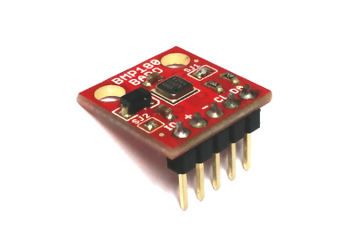
Note that the BMP180 is sensitive to moisture. When you're done soldering, do not clean off the flux by rinsing the board in water or other fluids.
Connecting the Board to your Arduino
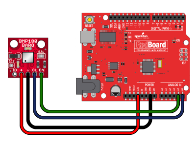
When you're done soldering, connect the +, -, CL, and DA pins to your Arduino. Different Arduino models use different pins for the I2C interface; use the following chart to determine where to plug everything in.
IMPORTANT: Connect the power pins (+ and -) ONLY to a 3.3V supply. Larger voltages will permanently damage the part. Note that because I2C uses open drain drivers, it is safe to connect the I2C pins (DA and CL) to an I2C port on a 5V microprocessor.
| BMP180 label | Pin function | Arduino connection | ||||||
| DA (SDA) | I2C data |
Any pin labeled SDA, or:
|
||||||
| CL (SCL) | I2C clock |
Any pin labeled SCL, or:
|
||||||
| "-" (GND) | ground | GND | ||||||
| "+" (VDD) | 3.3V power supply | 3.3V | ||||||
| IO (VDDIO) | I/O voltage | Leave disconnected unless you're connecting to a lower-voltage microprocessor |
Once you have the BMP180 connected to your Arduino, we're ready to play with the software.