Build a Qwiic Jukebox that is Toddler Approved!
 QCPete
Hardware Overview
Since, this system only uses Qwiic boards, it's really quite simple to plug everything together. The pictures below, show how everything should be plugged in. The RedBoard Qwiic, MP3 trigger, and RFID reader all have Qwiic connectors (the small black connectors with four pins) for a solderless project. The buttons will require a bit more of precision (plugging into the correct pins on the RedBoard Qwiic), but we will go into that with more detail in the next section.
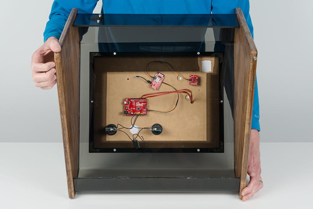
Back of project enclosure. (Click to enlarge.)

Hardward connections. (Click to enlarge.)
The Qwiic connectors and cables are polarized, so you don't have to worry about plugging in a cable backwards. The Qwiic boards can also be plugged in any order, they just need to daisy-chained together. This is handy as you may want a different order of connections depending on how your enclosure and faceplate are setup.
Buttons
The buttons need to be wired up to specific pins on the Arduino. These arcade buttons are actually made up of two parts. There is the large mechanical button that you press and then there is the electrical switch, which can be removed.
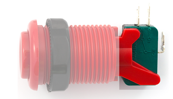
Button assembly. (Click to enlarge)
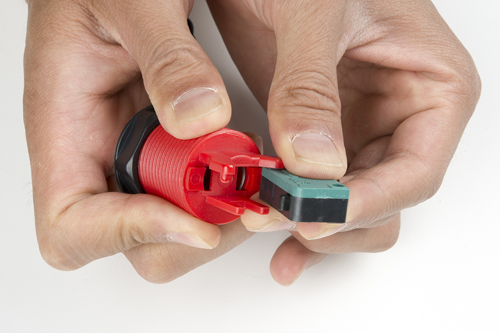
Removing switch from assembly. (Click to enlarge)
Above you can see the electrical switch removed from the larger housing. We need to connect the buttons to each Arduino pin as listed in the tables below. (COM stands for common and NO stands for normally open.)
Button one (PLAY):
| Button terminals | Arduino pins |
|---|---|
| NO | A0 |
| COM | GND |
Button two (STOP/PAUSE):
| Button terminals | Arduino pins |
|---|---|
| NO | A2 |
| COM | GND |
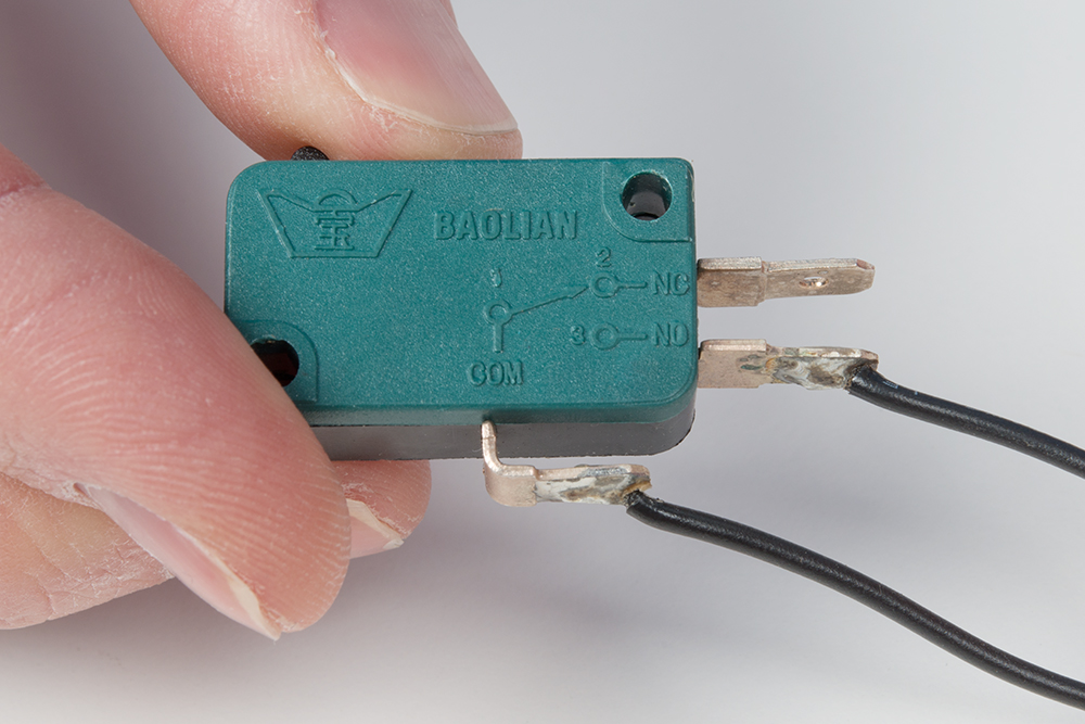
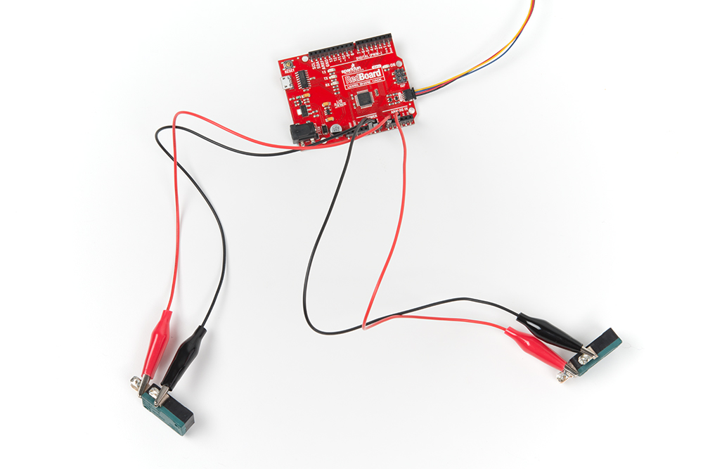
Close up of electrical switch. (Click to enlarge)
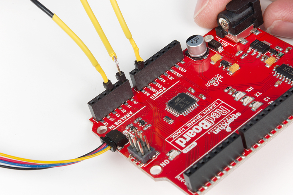
Wiring to RedBoard. (Click to enlarge)
Here, I've got some buttons pre-soldered. They were from a previous project. If you're comfortable soldering, then go ahead and solder it up! If you'd like to create this project without any soldering (and potentially involve the toddler a bit more), it can be done with our alligator to "pig-tail" cables.
You could also pull off this project with a single button, and change the functionality to just PLAY/PAUSE. The current code provided here uses the STOP button for two purposes. A single press of the STOP button will do just that, stop the track. But a double-press of the STOP button will PAUSE the track. Normally, the pause and play functions are tied to the same button, but this was a design choice my toddler made.
Power options
You have two options: Barrel jack or microB USB.
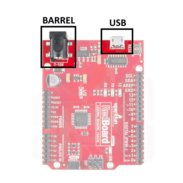
In the wish list above, we have included a USB wall adapter and a USB cable. This is nice because this cable can be used for programming and then also power. If you have a cell phone charger (with USB micro-B type connector), this would work fine too for simply powering after programming.
Speaking of power, the hamburger speaker get's about 3 hours of play time on each charge. If you'd like to avoid having to re-charge, you can leave this permanently plugged into a USB Mini-B type connector and additional USB wall adapter.