Bus Pirate v3.6a Hookup Guide
Board Overview
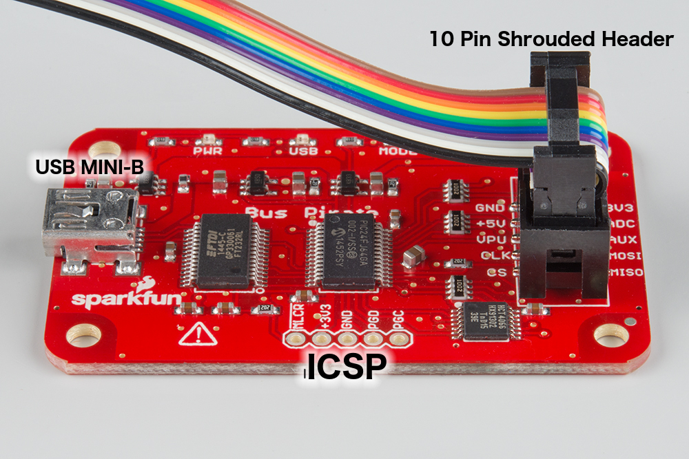
The Bus Pirate has 3 ports. This first is the ICSP port for directly programming the PIC microcontroller at the heart of this product. Since there is a bootloader and a reflashing utility, you shouldn't ever have to use this port.
The second port is a mini-B USB jack. Connect this to a computer with a standard A to mini-B cable. This provides the power to the board and allows you to communicate with Bus Pirate.
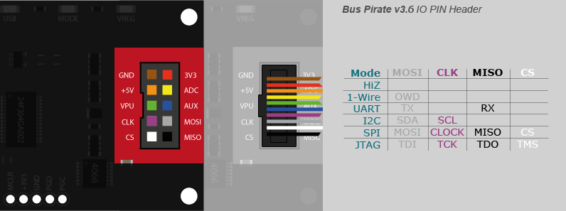
The third port is the most interesting. It's a shrouded 0.1" pitch 2x5 pin header. We sell a handy cable to connect the Bus Pirate to the system you are developing, debugging, or reverse engineering. Here is a graphic that shows maps the IO functions to the colors of the cable.
The following table describes in a little more detail the purpose of each pin. It's sorted in the same order as the conductors on the cable. The power supplies can be switched on or off in software, and each can supply up to 150mA to power your project.
| Pin Name | Description (Bus Pirate is the master) |
|---|---|
| GND | Ground, connect to ground of test circuit |
| +3.3V | +3.3 volt switchable power supply |
| +5.0V | +5 volt switchable power supply |
| ADC | Voltage measurement probe (max 6V) |
| VPU | Voltage input for on-board pull-up resistors (0V to 5V). |
| AUX | Auxiliary IO, frequency probe, pulse-width modulator |
| CLK | Clock signal (I2C, SPI, JTAG, KB) |
| MOSI | Master data out, slave in (SPI, JTAG), Serial data (1-Wire, I2C, KB), TX (UART) |
| CS | Chip select (SPI), TMS (JTAG) |
| MISO | Master data in, slave out (SPI, JTAG) RX (UART) |