Cackling Apple Head Witch
 Mando,
  MikeGrusin
Step 2: Programming the MP3 Trigger
While you're waiting for your apple head to shrink, let's get all the electronic bits together, and program the LilyPad MP3 Player with the sketch that will monitor the light sensor and play the scary sound when a shadow falls across it.
Testing the circuit
To make sure everything works before you start sewing it into your project, we recommend using alligator clips to temporarily make all the electrical connections. You can easily attach alligator clips to the bare metal around the holes on the LilyPad boards.
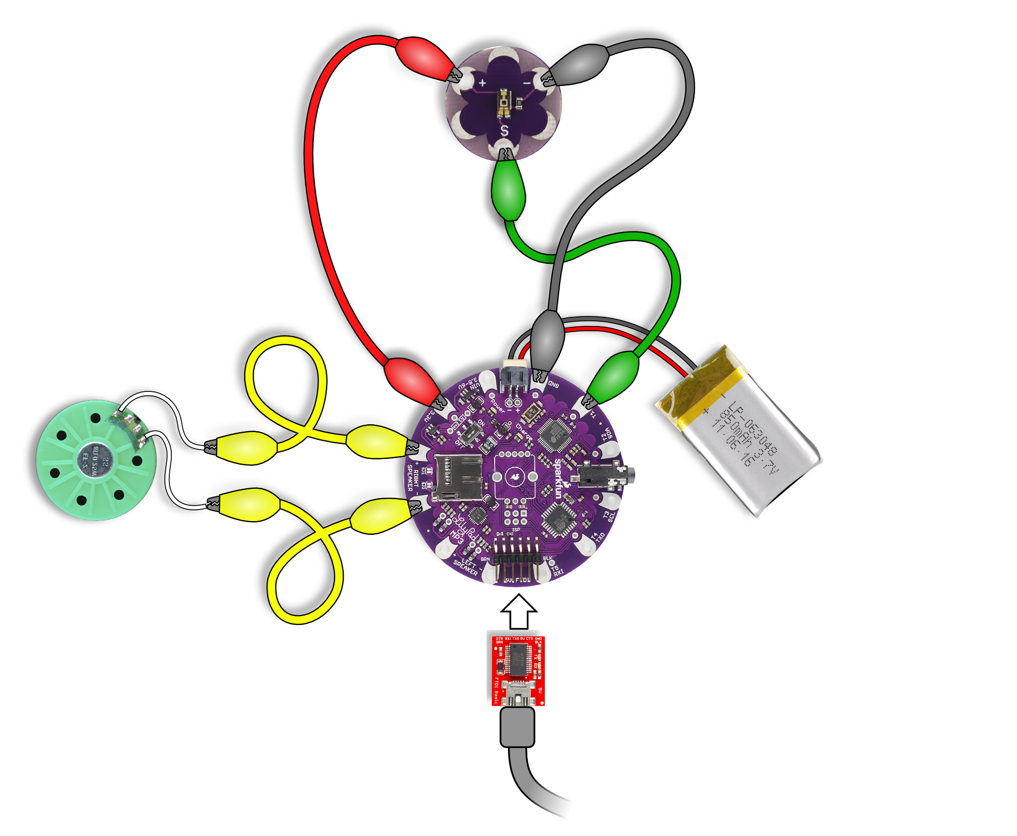
Follow the above diagram to make the following connections:
| from | to |
| LilyPad MP3 Player "3.3V" | LilyPad Light Sensor "+" |
| LilyPad MP3 Player "GND" | LilyPad Light Sensor "-" |
| LilyPad MP3 Player "T1" | LilyPad Light Sensor "S" |
| LilyPad MP3 Player "RIGHT SPEAKER +" | Speaker + * |
| LilyPad MP3 Player "RIGHT SPEAKER -" | Speaker - * |
| Lipo Battery | LilyPad MP3 Player battery connector |
| 5V FTDI board | LilyPad MP3 Player FTDI connector |
* It doesn't matter which side of the speaker you connect to "+" and "-". However, if you use two speakers, make sure they're both connected the same way.
OPTIONAL: You can use one or two speakers. If you want to use two speakers, connect one speaker to the right speaker connections (+ and -), and the second speaker to the left speaker connections (+ and -).
OPTIONAL: If you want to connect LEDs that light up while audio is playing, you can connect them between the LilyPad MP3 Player's T2 terminal and GND.
The 5V FTDI board is used to program the LilyPad MP3 Player and recharge the battery. Plug the FTDI board's socket into the 6-pin connector on the LilyPad MP3 Player, and plug the other end of the USB cable into your computer. (It's normal for the yellow "charge" LED to come on when you do this, it will go out when the battery is fully charged.)
TIP: If you look closely at the FTDI board, you'll see labels that say "GRN" (green) and "BLK" (black). Match these up with the labels on the LilyPad MP3 Player when you're plugging them together. (These "colors" match the wires on a different FTDI cable.)
Copy your sound file to the SD card
You can use almost any sound file you wish. Here's the one we're using for this project:
Right-click the above link, choose "Save link" to download the file to your computer, and copy it to your SD card. Insert the SD card into the socket on the LilyPad MP3 Player.
NOTE: The Arduino sketch (below) looks for a file called "cackle.mp3". If you use a different file, either rename it to "cackle.mp3", or change the filename at the top of the Arduino sketch.
Now, let's program the LilyPad MP3 Player!
Install the Arduino software
If you have never used the Arduino software before, go through our getting started tutorial first. This will walk you through installing the Arduino software on your computer.
Install the extra libraries
You'll now need to add the extra libraries needed to program the LilyPad MP3 Player. The easiest way to do this is:
- Go to the LilyPad MP3 Player Github page
- Click the "Download Zip" button on the right-hand side to download an archive of the files you need. Save it on your computer.
- Locate your personal Arduino folder. This should be in your documents folder.
- Open the archive you downloaded, open the "Arduino" folder inside it, and drag the contents of that folder into your personal Arduino folder.
If any of this is confusing, check out our Arduino library tutorial.
Load the sketch into the editor
Once you've done that, start the Arduino IDE, and copy and paste the following sketch into the editing window:
language:c
// Applehead_witch
// Demo program for Sparkfun's LilyPad MP3 Player
// Mike Grusin, SparkFun Electronics

// This sketch works with Amanda Clark's Apple Head Witch tutorial.
// If your shadow passes over an innocent-looking apple-head doll,
// the LilyPad MP3 Player will play a scary sound!

// HOW IT WORKS:

// The sketch monitors a light sensor connected to TRIG1.
// When the sketch first runs, it will sample a baseline light level
// and compute a threshold value (baseline * 0.9). After that, if the
// light level falls below this threshold, a sound file will play.
// Also, TRIG2 will be set to HIGH while the file is playing, and
// LOW otherwise (for optional scary LED eyes or other features).

// SOFTWARE INSTALLATION:

// If you haven't yet, you should install the LilyPad MP3 Player
// libraries available here: https://github.com/sparkfun/LilyPad_MP3_Player

// HARDWARE CONNECTIONS:

// Connect the "S" pin of the LilyPad Light Sensor to TRIG1.
// Also connect 3.3V to the Light Sensor's "+" pin, and
// GND to the Light Sensor's "-" pin.
// (Optional) Connect TRIG2 to LEDs through a resistor for 3.3V supply.
// (330 Ohms is a common value).
// Connect one or two speakers to the left and/or right speaker terminals.
// Put a sound file on a microSD card and place it in the player.
// Change the below filename to match the one you put on the SD card:

char filename[] = "cackle.mp3";

// Connect a 3.7V Lipo battery to the battery connector.
// Connect a 5V FTDI Basic Breakout.
// Remember to turn on the player before programming it!

// RUNNING THE SKETCH

// When you first run the sketch, the light sensor will be sampled for
// the baseline light level. So have the project in it's installed position,
// and avoid casting shadows on it, before turning it on.

// Once it is on, when you cast a shadow over the project, it should play
// the audio file through the speaker.

// If it doesn't activate properly (too often or not often enough),
// you can adjust the sensitivity value below.
// The sensitivity can be from 0.0 to 1.0. The closer it is to 1.0, the more
// sensitive the sketch will be. If you make it 1.0, it will probably activate
// continuously.
// If your project it too sensitive, make the sensitivity smaller.
// If your project is not sensitive enough, make the sensitivity larger.

const float sensitivity = 0.9;

// If the sketch does not work properly, connect your 5V FTDI and open a
// Serial Monitor at 9600 baud to receive debugging information.

// HAVE FUN!
// Your friends at SparkFun


// We'll need a few libraries to access all this hardware!

#include <SPI.h>            // To talk to the SD card and MP3 chip
#include <SdFat.h>          // SD card file system
#include <SFEMP3Shield.h>   // MP3 decoder chip

// Constants for the trigger pins:

const int TRIG1 = A0;
const int TRIG2 = A4;

// Save the light sensor baseline reading:

int threshold;

// And a few output pins we'll be using:

const int ROT_LEDR = 10; // Red LED in rotary encoder (optional)
const int EN_GPIO1 = A2; // Amp enable + MIDI/MP3 mode select
const int SD_CS = 9;     // Chip Select for SD card

// Create library objects:

SFEMP3Shield MP3player;
SdFat sd;

// Set debugging = true to send status messages to the serial port:

boolean debugging = true;


void setup()
{
  byte result;

  // Use TRIG1 as an anlog input for our light sensor:

  pinMode(TRIG1,INPUT);

  // Use TRIG2 as a digital output that will be HIGH
  // while we're playing an audio file and LOW otherwise:

  pinMode(TRIG2,OUTPUT);
  digitalWrite(TRIG2,LOW);

  // If serial port debugging is inconvenient, you can connect
  // a LED to the red channel of the rotary encoder to blink
  // startup error codes:

  pinMode(ROT_LEDR,OUTPUT);
  digitalWrite(ROT_LEDR,HIGH);  // HIGH = off

  // The board uses a single I/O pin to select the
  // mode the MP3 chip will start up in (MP3 or MIDI),
  // and to enable/disable the amplifier chip:

  pinMode(EN_GPIO1,OUTPUT);
  digitalWrite(EN_GPIO1,LOW);  // MP3 mode / amp off

  // If debugging is true, initialize the serial port:
  // (The 'F' stores constant strings in flash memory to save RAM)

  if (debugging)
  {
    Serial.begin(9600);
    Serial.println(F("Lilypad MP3 Player trigger sketch"));
  }

  // Initialize the SD card; SS = pin 9, half speed at first

  if (debugging) Serial.print(F("initialize SD card... "));

  result = sd.begin(SD_CS, SPI_HALF_SPEED); // 1 for success

  if (result != 1) // Problem initializing the SD card
  {
    if (debugging) Serial.print(F("error, halting"));
    errorBlink(1); // Halt forever, blink LED if present.
  }
  else
    if (debugging) Serial.println(F("success!"));

  // Start up the MP3 library

  if (debugging) Serial.print(F("initialize MP3 chip... "));

  result = MP3player.begin(); // 0 or 6 for success

  // Check the result, see the MP3 library readme for error codes.

  if ((result != 0) && (result != 6)) // Problem starting up
  {
    if (debugging)
    {
      Serial.print(F("error code "));
      Serial.print(result);
      Serial.print(F(", halting."));
    }
    errorBlink(result); // Halt forever, blink red LED if present.
  }
  else
    if (debugging) Serial.println(F("success!"));

  // Set the VS1053 volume. 0 is loudest, 255 is lowest (off):

  MP3player.setVolume(10,10);

  // Get baseline readings from the light sensor:

  threshold = (analogRead(TRIG1));
  if (debugging)
  {
    Serial.print(F("measured threshold value: "));
    Serial.println(threshold);
  }

  threshold = threshold * sensitivity;
  if (debugging)
  {
    Serial.print(F("modified threshold value: "));
    Serial.println(threshold);
  }

  // Turn on the amplifier chip:

  digitalWrite(EN_GPIO1,HIGH);
  delay(2);
}


void loop()
{
  byte result;
  byte sensorvalue;

  // Get the current light level (sensorvalue):

  sensorvalue = analogRead(TRIG1);

  if (debugging)
  {
    Serial.print(F("sensor value: "));
    Serial.print(sensorvalue);
    Serial.print(F("  threshold: "));
    Serial.println(threshold);
  }

  // Check to see whether we're below the threshold

  if (sensorvalue < threshold)
  {
    if(debugging)
    {
      Serial.println(F("got a trigger!"));
    }

    // If we're currently playing a file, let it finish (don't start over)

    if (MP3player.isPlaying())
    {
      if(debugging)
      {
        Serial.println(F("...but we're already playing"));
      }
    }
    else
    {
      // Play the file!

      result = MP3player.playMP3(filename);

      // Print out error information for debugging

      if(debugging)
      {
        if(result != 0)
        {
          Serial.print(F("error "));
          Serial.print(result);
          Serial.print(F(" when trying to play track "));
        }
        else
        {
          Serial.print(F("playing "));
        }
        Serial.println(filename);
      }
    }
  }

  // For fun, we'll set TRIG2 HIGH while we're playing a file,
  // and LOW when the player is silent.

  if (MP3player.isPlaying())
    digitalWrite(TRIG2,HIGH);
  else
    digitalWrite(TRIG2,LOW);
}


void errorBlink(int blinks)
{
  // The following function will blink the red LED in the rotary
  // encoder (optional) a given number of times and repeat forever.
  // This is so you can see any startup error codes without having
  // to use the serial monitor window.

  int x;

  while(true) // Loop forever
  {
    for (x=0; x < blinks; x++) // Blink the given number of times
    {
      digitalWrite(ROT_LEDR,LOW); // Turn LED ON
      delay(250);
      digitalWrite(ROT_LEDR,HIGH); // Turn LED OFF
      delay(250);
    }
    delay(1500); // Longer pause between blink-groups
  }
}
Upload the sketch to the LilyPad MP3 Player
Turn the power switch on the LilyPad MP3 Player to ON. The red LED should light up.
In the Arduino IDE, go to the "tools/board" menu. Select Arduino Pro or Pro Mini (3.3V, 8MHz) w/ ATmega328.
Now go to the "tools/serial port" menu. Select the serial port that your FTDI is using. If you just installed it, this will be the highest number.
Now click the right-arrow button above the editing window. This will compile the sketch and upload it through the FTDI board to the LilyPad MP3 Player.
Hopefully you'll see some blinking on the FTDI, followed by an "upload successful" message. If there are errors, see the troubleshooting tips below.
Try it out!
Once you've uploaded the sketch, it will automatically start running. The first thing the sketch does is take a baseline reading from the light sensor. It will then keep monitoring the sensor, and if the sensor dips below that level (such as when a shadow passes across it), it will play the scary sound. For best results, whenever you turn your project on, try not to be casting a shadow over it.
Try passing your hand over the light sensor, and see if it plays the scary sound.
If it works, congratulations! If not, don't worry, see the troubleshooting tips below.
Once you know everything works, you're ready to build the rest of your project. Note that you won't have to reprogram the LilyPad MP3 Player again (unless you want to), it will remember the last sketch you uploaded to it!
Troubleshooting
Syntax errors are almost always caused by not restarting the Arduino IDE after installing the libraries, or not installing the libraries correctly. Check your above steps to make sure you placed the new libraries into a "libraries" directory within your personal Arduino sketch folder.
Uploading errors may be caused by the LilyPad MP3 Player being switched off (it must be on to upload code), The FTDI drivers not being installed correctly, or selecting the wrong port in the "tools/serial port" menu.
No sound? If the code uploaded without errors but the sound still doesn't play, try looking at the debugging information. In the Arduino IDE, click on the magnifying glass button at the upper right. This will open a serial monitor window. Set the baud rate (bottom of window) to 9600 baud.
The LilyPad MP3 Player should now fill the window with text showing what it's doing and if there are any problems such as not being able to find the SD card or the proper filename on it.
Still stumped? If after all this you still can't get it working, don't panic! You can always contact our Tech Support Department. They'll be happy to help you get up and running.