Capacitors
 jimblom
Symbols and Units
Circuit Symbols
There are two common ways to draw a capacitor in a schematic. They always have two terminals, which go on to connect to the rest of the circuit. The capacitors symbol consists of two parallel lines, which are either flat or curved; both lines should be parallel to each other, close, but not touching (this is actually representative of how the capacitor is made. Hard to describe, easier to just show:
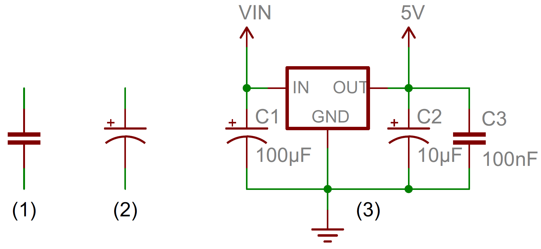
The symbol with the curved line (#2 in the photo above) indicates that the capacitor is polarized, meaning it's probably an electrolytic capacitor. More on that in the types of capacitors section of this tutorial.
Each capacitor should be accompanied by a name -- C1, C2, etc.. -- and a value. The value should indicate the capacitance of the capacitor; how many farads it has. Speaking of farads...
Capacitance Units
Not all capacitors are created equal. Each capacitor is built to have a specific amount of capacitance. The capacitance of a capacitor tells you how much charge it can store, more capacitance means more capacity to store charge. The standard unit of capacitance is called the farad, which is abbreviated F.
It turns out that a farad is a lot of capacitance, even 0.001F (1 milifarad -- 1mF) is a big capacitor. Usually you'll see capacitors rated in the pico- (10-12) to microfarad (10-6) range.
| Prefix Name | Abbreviation | Weight | Equivalent Farads |
|---|---|---|---|
| Picofarad | pF | 10-12 | 0.000000000001 F |
| Nanofarad | nF | 10-9 | 0.000000001 F |
| Microfarad | µF | 10-6 | 0.000001 F |
| Milifarad | mF | 10-3 | 0.001 F |
| Kilofarad | kF | 103 | 1000 F |
When you get into the farad to kilofarad range of capacitance, you start talking about special caps called super or ultra-capacitors.