CCS811 Air Quality Breakout Hookup Guide
 MTaylor
Hardware Overview
The CCS811 is supported by only a few passives, and so the breakout board is relatively simple. This section discusses the various pins on the board.
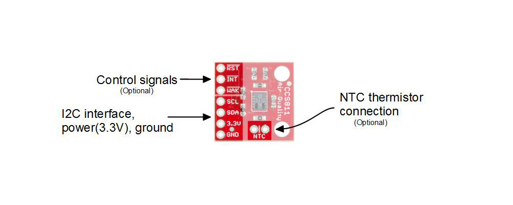

Pins
| Pin | Description | Direction |
|---|---|---|
| RST | Reset (active low) | In |
| INT | Interrupt (active low) | Out |
| WAK | Wake (active low) | In |
| SCL | Clock | In |
| SDA | Data | In |
| 3.3V | Power | In |
| GND | Ground | In |
| NTC (2 pins) | Negative thermal coefficient resistor | N/A |
Power and I2C Bus
The minimum required connections are power, ground SDA and SCL. Supply a regulated 3.3V between the board's 3.3V pin and ground terminals. The sensor consumes an average of 12mA of current.
The I2C bus has pull-up resistors enabled by default. If not desired, these can be removed by separating the "I2C PU" triple jumper on the bottom side with a hobby knife.
An I2C address can be either 0x5A or 0x5B. The "ADDR" jumper is connected with copper from the factory, corresponding to a default address of 0x5B. Close this jumper to use the address 0x5A.
Control lines
Additionally, the three control lines RST, INT and WAK can be used to further the degree of control.
- RST --- Pull this line low to reset the IC.
- INT --- After configuring the sensor to emit interrupt requests, read this line to determine the state of the interrupt.
- WAK --- Pull this line high to put the sensor to sleep. This can be used to save power but is not necessary if power is not an issue.
NTC Thermistor operation
A thermistor can be used to determine the temperature of the CCS811's surroundings, which can be used to help compensate the readings. You'll need your own 10K NTC thermistor, such as our 10K Thermistor, soldered between the "NTC" pins. A thermistor is a nonpolarized device, so it can go in either way.