Constant Innovation in Quality Control
 QCPete
Multi-Board Programming
Our first approach to multi-board programming involved multiple programmers, a USB hub, a bunch of cables, and some tricky batch file action.
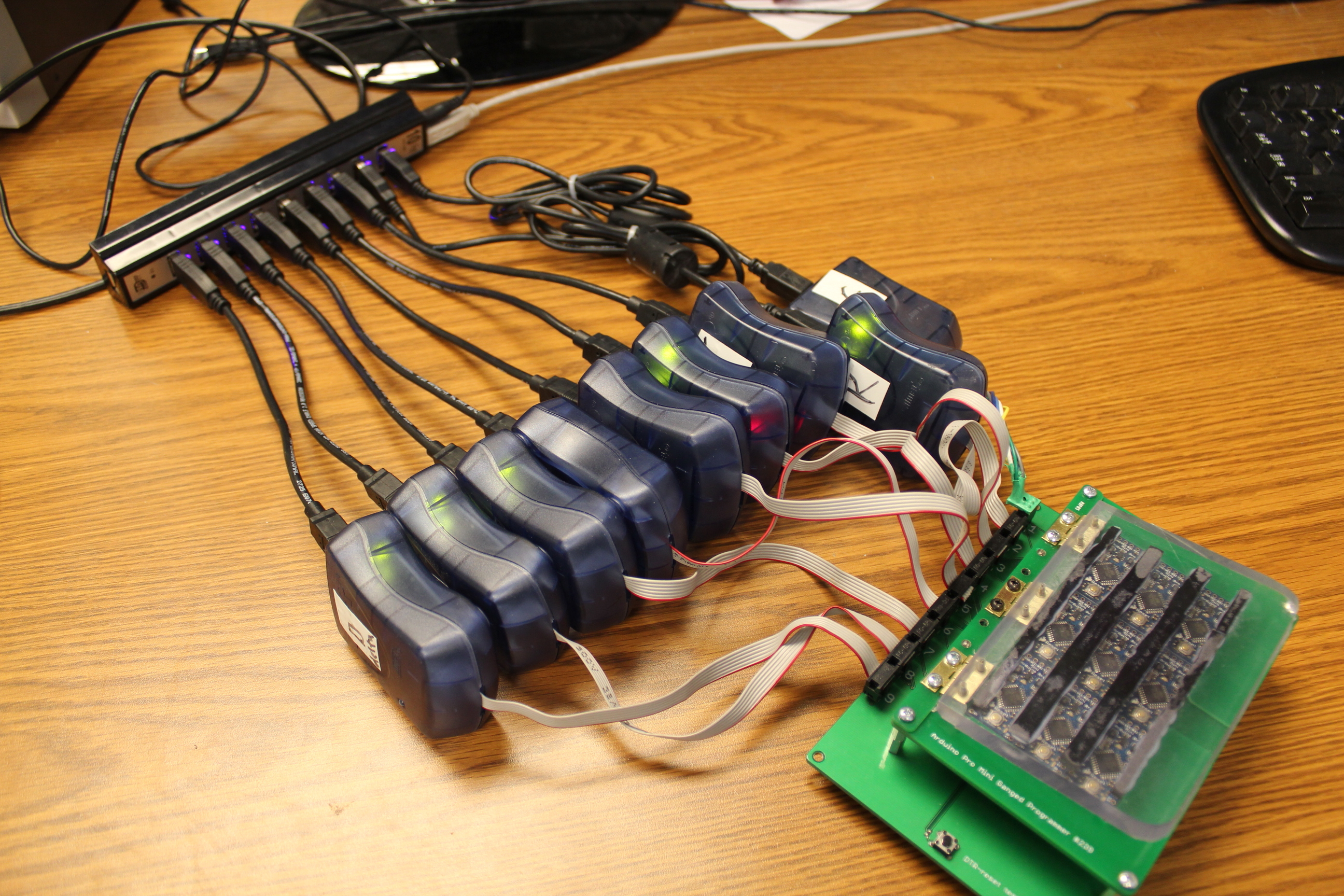
It sure did speed up our production runs. Nine at a time was a huge improvement from our previous single board programming methods. But, as with most of our testing equipment, it eventually became out-dated, and we wanted to upgrade it.
It became a bit of a hassle to setup -- ensuring that everything was plugged in properly. And over the years, the ribbon cables began to wear out. In November of 2011, we posted a very thorough tutorial on how this ganged-programmer works. Click HERE to check that out. In addition to the hardware design ideas, it actually was a great exercise in using batch files.
About a year after the release of the above programmer, we started having a lot of our technicians computers freeze up mid programming. The famous blue screen of death was happening far too often. We replaced the USB hubs with better quality hubs, and this seemed to help the problem a bit. However, we knew another approach was needed.
We wanted to find a way to program multiple boards simultaneously using one single programmer. Our first thought was to use some sort of amplification or buffer on the programming lines.
To program an AVR using ISP, there are 6 connections that need to be made from the programmer to the target IC:
- VCC
- GND
- RESET
- SCK
- MISO
- MOSI
Experimenting with our logic level converter, we were able to get a few boards to program off one single programmer. Our initial hardware was as follows.
Physically bussing (as in metal connections on the same net) for the GND, VCC and RESET.
SCK and MOSI needed to be buffered, because these signals were being sent to multiple targets. It seemed that the MKII did not have enough output impedance to program multiple targets, so we sent them through the logic level converter. This way, the signal strength was relying on the HIGH logic pin of the converter and not the output of the MKII.
The MISO line was a little trickier. This line carries communication from the target back to the programmer. And if you have a few targets all trying to talk back to the programmer at the same time, the programmer would not understand the returning data. The solution we found was to have only one single target IC talk back to the programmer. This way, the programmer thought it was only talking with one IC and the remaining target ICs on the bus would simply listen along. We figured we could test the solder joint on the remaining ICs MISO lines with some sort of other testcode later.
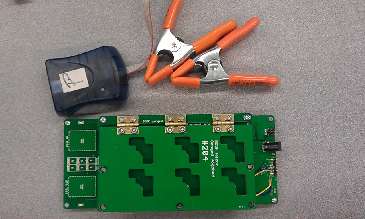
Above is a picture of the first testing hardware to include a buffered programming circuit. It was used for the Arduino Pro Mini. It could program six boards at a time and lived a decent life on the production floor. If you look closely at the top left you can see the prototyping board and logic level converter used on the programing lines. Unfortunately, this is the best picture I could dig up. It has since been upgraded to a new version (that includes a hex converter buffer circuit). The original hardware pictured above must have been tossed into our electronics recycling.
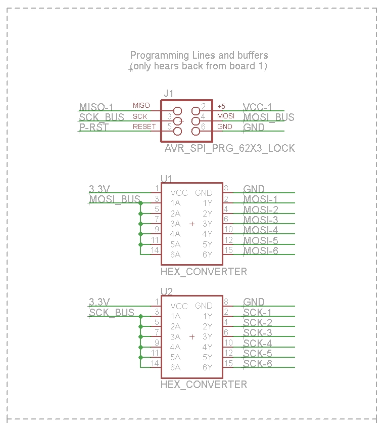
We then incorporated the transistor buffer into the testbed PCB, as show below in the this section of the schematic:

The latest models in production incorporates a hex converter to amplify the SCK and MISO lines like so:
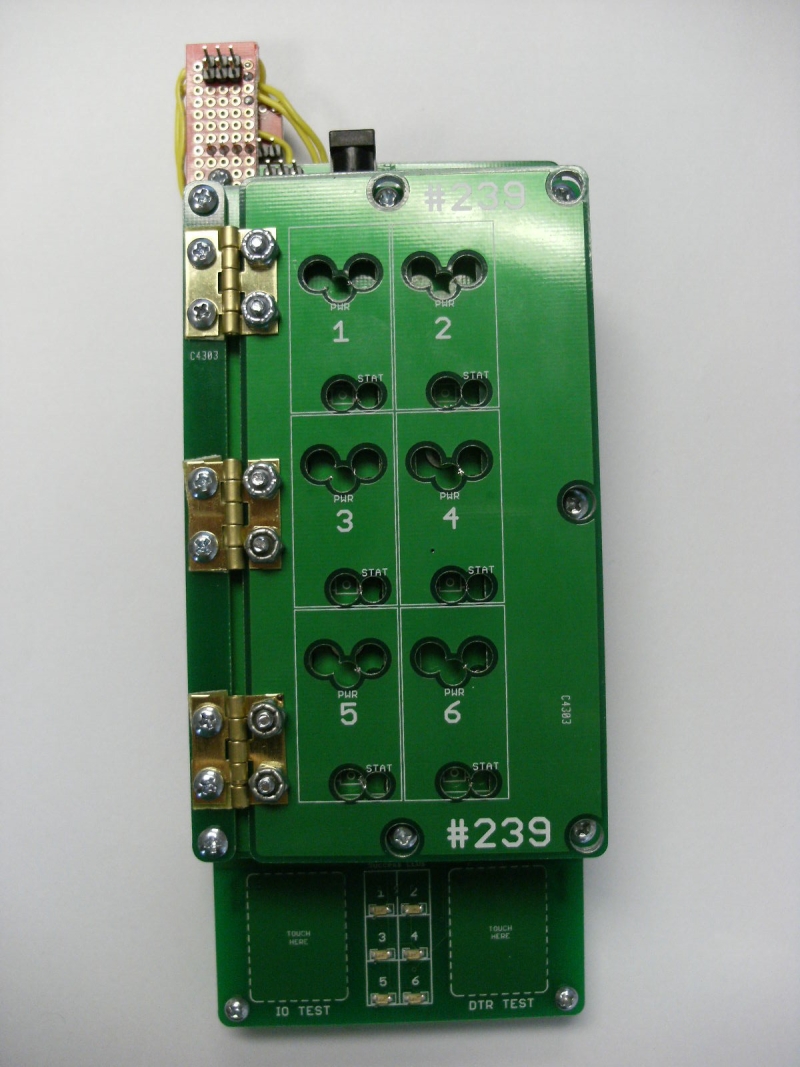
Below is a picture of the latest ganged programmer for the 9 Degrees of Freedom - Razor IMU. It programs six boards at a time and only uses one programmer.
It also has some other advancements including the waffle top, capsense buttons and more. The next few sections of this article are dedicated to some of these other improvements. Read on to learn more.