DA16200 Thing Plus Hookup Guide
Introduction
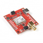
The SparkFun Thing Plus - DA16200 utilizes a highly integrated ultra-low power WiFi system on chip (SoC) that allows users to develop WiFi and IoT solutions.
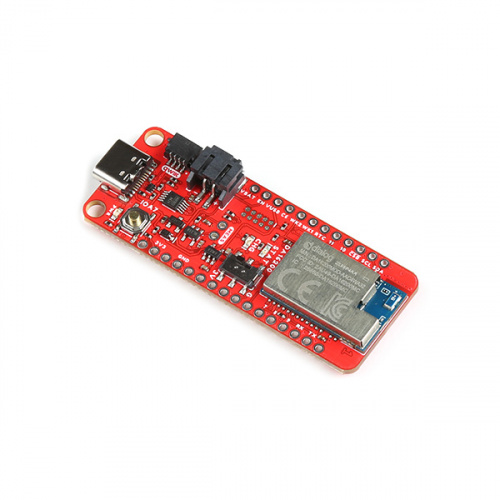
Manufactured by Dialog (a subsidiary of Renesas), the DA16200MOD contains a 802.11b/g/n radio (PHY), a baseband processor, a media access controller (MAC), on-chip memory, and a host networking application processor, all on a single silicon die. The SoC has full offload capabilities to run the entire networking OS and TCP/IP stack on chip; therefore, an external network processor, CPU, or microcontroller are not required. The module is also Wi-Fi Alliance certified for IEEE802.11b/g/n, Wi-Fi Direct, WPS functionalities in many countries including the United States (FCC), Canada (IC) and China (SRRC).
This board comes in a Thing Plus form factor, which includes a Qwiic and LiPo battery connectors, multiple GPIO pins, and JTAG PTH pins for debugging. The SparkFun Thing Plus - DA16200 is ideal for your next IoT project, thanks in part to the multiple sleep modes that allow you to take advantage of current draws as low as 0.2 - 3.5 µA on the WiFi module.
Required Materials
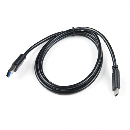
To get started, users will need a USB-C cable is needed to connect the DA16200 Thing Plus to a computer. (You may already have a some of these items; read through the guide and modify your cart accordingly.)


Optional Hardware
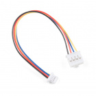
To connect Qwiic breakout boards for your project, Qwiic cables are required.


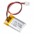
A single-cell Lithium-ion battery can be connected to the DA16200 Thing Plus for portability.


To modify the jumpers, users will need soldering equipment and/or a knife.


Suggested Reading
For users who aren't familiar with the following concepts, we also recommend reading the following tutorials before continuing.
How to Install CH340 Drivers
Dialog ULP WiFi DA16200 R3 Shield Hookup Guide
MicroMod WiFi Function Board - DA16200 Hookup Guide
Getting Started with the DA16200 FreeRTOS SDK
How to Solder: Through-Hole Soldering
Serial Communication
Serial Peripheral Interface (SPI)
Analog vs. Digital
Serial Terminal Basics
Connectivity of the Internet of Things
How to Work with Jumper Pads and PCB Traces
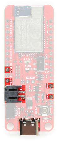
Hardware Overview
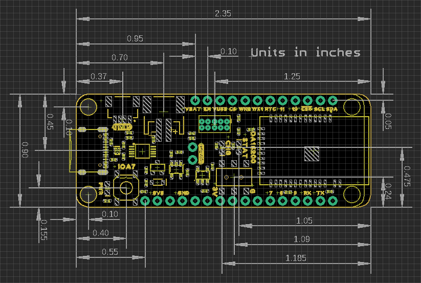
Board Dimensions
The SparkFun Thing Plus - DA16200's pin layout has a feather form factor. The board dimensions are illustrated in the drawing below.
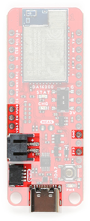
USB-C Connector
The USB connector is provided to power and interact with the board. For most users, it will be the primary programing interface for the DA16200 module.
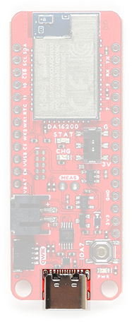
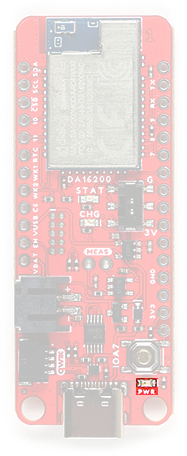
CH340 Serial-to-UART
The CH340 allows the DA16200MOD to communicate with a computer/host device through the board's USB-C connection. This allows the board to show up as a device on the serial (or COM) port of the computer. Users will need to install the latest drivers for the computer to recognize the board (see Software Overview section).
Power
The DA16200 Thing Plus only requires 3.3V to power the board. However, the simplest method to power the board is through the USB-C connector. Alternatively, the 3V3, VBAT, and VUSB pins can also be used to supply power to the board.
VUSB:- The maximum voltage for the LDOs and charge controller is 6V.
- The minimum voltage for the charge controller is 3.75V.
VBAT:- Should not be connected to anything other than a single-cell LiPo battery.
3V3:- Requires a regulated 3.3V.
- Powers the board and the Qwiic connector.
The power pins that are available on the board, are detailed below: Below, is a general summary of the power circuitry on the board:
3V3- Provides a regulated 3.3V from the USB (5V) power and/or battery connections.- Powers the DA16200MOD, status LEDs (
PWRandSTAT), and 3.3V connections of the Qwiic connector (I2C bus) and debug pins. - The 3.3V XC6222 LDO regulator can source up to 700mA.
- The output is controlled by the
ENpin on the board.
- The output is controlled by the
- Pin can also operate as an input from an external power source.
- Powers the DA16200MOD, status LEDs (
VUSB- The voltage from the USB-C connector, usually 5V.- Power source for the entire board.
- Provides power to the 3.3V voltage regulator and the battery charging circuit.
- Overides power from the battery through a P-channel MOSFET, when both are connected.
- Contains ESD protection for the USB-C connection.
- Power source for the entire board.
VBAT- The voltage from the JST battery connector; meant for single cell LiPo batteries.- Provides power to the 3.3V voltage regulator.
- The MCP73831 linear charge management controller is powered from the USB (5V) power supply.
- The charge controller is configured for 500mA (max) rate of charge to a connected battery.
GND- The common ground or the 0V reference for the voltage supplies.- Qwiic Connector - Provides a regulated 3.3V output.
For more details, users can reference the schematic and the datasheets of the individual components in the power circuitry.
Power Status LED
The red, POWER LED will light up once 3.3V is supplied to the board; however, for most users, it will light up when 5V is supplied through the USB connection or when a LiPo battery is connected to the JST connector.
POWER status LED indicator. (Click to enlarge) Charging Circuit
The charging circuit utilizes the MCP73831 linear charge management controller and is powered directly from the USB-C connector or VUSB. The controller is configured for a 500mA charge rate and active charging is indicated by the yellow, CHG LED. If the charge controller is shutdown or charging is complete, the CHG LED will turn off. For more information, please refer to the MCP73831 datasheet and the Indicator LEDs section below.
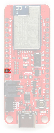
Power Control
The power source to the XC6222 is controlled by a P-channel MOSFET. In addition, the 3.3V regulated output from the XC6222 is controlled by the enable (EN) pin, broken out on the board. By default, the chip enable pin (EN) is pulled high, to enable the 3.3V output, supply voltage. To disable and shutdown the output voltage from the XC6222, the chip enable pin (EN) needs to be pulled low (i.e. shorted to ground (GND)). For more information, pleas refer to the XC6222.
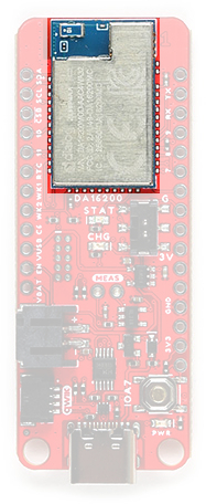
DA16200MOD WiFi Module
The DA16200MOD is an ultra low power WiFi module manufactured by Dialog (a subsidiary of Renesas). It contains a 802.11b/g/n radio (PHY), a baseband processor, a media access controller (MAC), on-chip memory, and a host networking application processor, all on a single silicon die. The system on a chip (SoC) has full offload capabilities to run the entire networking OS and TCP/IP stack on chip; therefore, an external network processor, CPU, or microcontroller are not required. The DA16200 is ideal for your next IoT project, thanks to the multiple sleep modes that allow you to take advantage of current draws as low as 0.2 - 3.5 µA.
- Operating voltage: 2.1 to 3.6 V
- Operating temperature: -40 to 85 °C
- Arm® Cortex®-M4F core w/ clock frequency of 30~160 MHz
- ROM: 256 kB
- SRAM: 512 kB
- OTP: 2 kB
- Retention SRAM: 48 kB
- WiFi processor
- IEEE 802.11b/g/n, 20MHz channel bandwidth, 2.4GHz (up to 54 Mbps)
- IEEE 802.11s Wi-Fi mesh
- WiFi security: WPA/WPA2-Enterprise/Personal, WPA2 SI, WPA3 SAE, and OWE
- Operating modes: Station, SoftAP, and Wi-Fi Direct® Modes (GO, GC, GO fixed)
- SPI flash Memory: 32 Mb (4 MB)
- On-Chip RTC (± 250 ppm)
- Three ultra-low power sleep modes
The module is Wi-Fi Alliance certified for IEEE802.11b/g/n, Wi-Fi Direct, WPS functionalities and it has been approved by many countries including the United States (FCC), Canada (IC) and China (SRRC). Using the Wi-Fi Alliance transfer policy, the Wi-Fi Certifications can be transferred without being tested again.
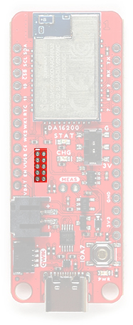
JTAG
The DA16200 Thing Plus includes JTAG PTH pins for a JTAG header, to be used with debugging probe. The JTAG pins breakout the SWD (software debug) pins to the DA16200MOD module.
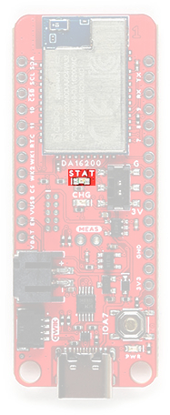
RTC Switch
On the DA16200 Thing Plus, a switch is provided to control the state of the RTC_PWR_KEY pin. The RTC_PWR_KEY of the DA16200MOD is a pin that enables the RTC block; the switch essentially controls if the DA16200MOD module is in Sleep Mode 1 and acts as an external WiFi module.
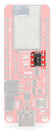
RTC swirtch on the DA16200 Thing Plus. (Click to enlarge)
| Position | Notes |
|---|---|
| G |
Sleep Mode 1 - RTC Block Disabled The DA16200MOD module should be controlled/operated by an external MCU. |
| 3V | The DA16200MOD module is in a normal active state. However, the module can still enter the Sleep Mode 2/3 states. |
Indicator LEDs
There are three indication LEDs on the DA16200 Thing Plus for:
PWR: Power (Red)CHG: Battery Charging (Yellow)STAT:GPIO A11(Blue)
Power LED
The red, PWR LED will light up once 3.3V is supplied to the board. For most users, it will light up when 5V is supplied through the USB connection and/or when a LiPo battery is attached to the JST connector.
PWR status LED indicator. (Click to enlarge) Battery Charging LED
The yellow, CHG LED will light while a battery is being charged through the charging circuit. The LED will be off when no battery is present, when the charge management controller is in standby (after the battery charging has been completed), or when the charge management controller is shutdown (thermal shutdown or when the input voltage is lower than the battery voltage). The LED will be on when the charge management controller is in the process of charging the battery. For more information, please refer to the MCP73831 datasheet.
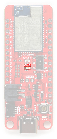
The battery charging (
CHG) LED indicator on the DA16200 Thing Plus. (Click to enlarge)
| Charge Cycle State | STATE |
|---|---|
Shutdown
|
Off (High Z) |
| No Battery Present* | Dimmed (High Z) |
| Charge Complete – Standby | Off (H) |
| Preconditioning | On (L) |
| Constant-Current Fast Charge | On (L) |
| Constant Voltage | On (L) |
Status LED
The blue, STAT LED is typically used as a test or status LED to make sure that a board is working or for basic debugging. This indicator is connected to GPIO A11.
GPIO A11 on the DA16200 Thing Plus. (Click to enlarge) Reset Button
The RESET button is connected to the GPIO A7 and is used to factory reset the module; press and hold the
button for more than 5 seconds to initialize nvram data.
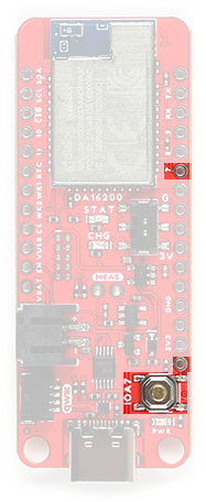
RESET button on the DA16200 Thing Plus. (Click to enlarge) I2C Bus
The I2C bus for this board utilizes the GPIO connections, detailed in the table below:
| Connection | VDD |
GND |
SCL |
SDA |
|---|---|---|---|---|
| GPIO | 3.3V | GND | GPIO A1 |
GPIO A0 |
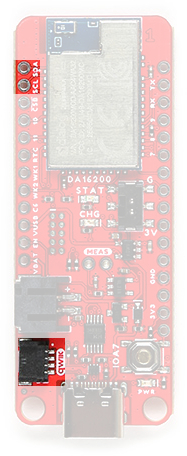
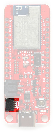
Qwiic Connector
A Qwiic connector is provided for users to seamlessly integrate with SparkFun's Qwiic Ecosystem.
What is Qwiic?
The Qwiic system is intended a quick, hassle-free cabling/connector system for I2C devices. Qwiic is actually a play on words between "quick" and I2C or "iic".
Features of the Qwiic System
Keep your soldering iron at bay.
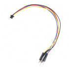
Cables plug easily between boards making quick work of setting up a new prototype. We currently offer three different lengths of Qwiic cables as well as a breadboard friendly cable to connect any Qwiic enabled board to anything else. Initially you may need to solder headers onto the shield to connect your platform to the Qwiic system but once that’s done it’s plug and go!

Qwiic cables connected to Spectral Sensor Breakout
Minimize your mistakes.
How many times have you swapped the SDA and SCL wires on your breadboard hoping the sensor will start working? The Qwiic connector is polarized so you know you’ll have it wired correctly, every time, from the start.
The PCB connector is part number SM04B-SRSS (Datasheet) or equivalent. The mating connector used on cables is part number SHR04V-S-B or equivalent. This is a common and low cost connector.

1mm pitch, 4-pin JST connector
Expand with ease.
It’s time to leverage the power of the I2C bus! Most Qwiic boards will have two or more connectors on them allowing multiple devices to be connected.

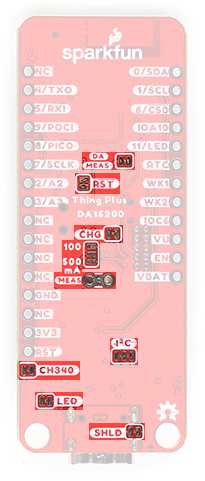
Jumpers
There are six jumpers on the DA16200 Thing Plus.
There are four adjustable solder jumpers on the mikroBUS™ carrier board labeled MEAS, BYP, 3.3V_VE and 3.3V. The table below briefly outlines their functionalities:
| Jumper Name/Label | Description | Default State |
|---|---|---|
| SHLD - USB-C Shield |
Connects the shield of the USB-C connector (metal housing) to the GND plane of the board. Users should cut the jumper when they need to isolate the shield of the USB-C connector from the board's ground plane. |
CLOSED |
| I2C - I2C Pull-Up |
Pulls the SDA/SCL lines up to 3.3V via two 2.2K Ohm resistors. Users should cut the jumper, when there are multiple devices on the I2C bus with pull up resistors. By removing the pull up resistors from the SDA and SCL lines, the strength of the pull up resistance will be reduced.
|
CLOSED |
| MEAS - Measure |
Connects the USB and battery power to the voltage regulator. Users should cut the jumper to probe the current draw into the 3.3V regulator. For help measuring current, take a look at our How to Use a Multimeter tutorial. |
CLOSED |
| LED - |
Connects the PWR LED (red) to the 3.3V power.Users should disconnect this jumper to reduce the current consumption of the board. |
CLOSED |
| CHG - |
Connects the CHG LED (YLW) to the MCP73831.Users should disconnect this jumper to reduce the current consumption of the board. |
CLOSED |
| 100/500 mA |
This jumper is used to select the charge rate to the LiPo battery from the MCP73831. Users should modify this jumper to reduce the available charrge current to the LiPo battery. |
500 mA |
| CH340 |
Connects the CH340 Serial-to-UART chip to 3.3V power. Users should disconnect this jumper to reduce the current consumption of the board. |
CLOSED |
| RST - Reset |
Connects GPIO A7 to the IOA7 button and the RST PTH pin.Users should cut the jumper to disconnect the GPIO pin from the pull up resistor and isolaate the GPIO from the IOA7 button and the RST PTH pin.
|
CLOSED |
| DA MEAS - DA16200MOD |
Connects 3.3V to the DA16200MOD module. Users should cut this jumper to measure the current directly to the DA16200MOD. Users can make their measurements through the jumper pads. |
CLOSED |
Note: When modifying these jumpers, be careful to avoid cutting nearby traces. Although not usually an issue, we thought to mention that this board is also a 4-layer PCB, so be careful not to cut the jumper too deep.

Traces (blue) near the jumpers on the DA16200 Thing Plus. (Click to enlarge)
Software Overview
Driver
Users will need to install the CH340 driver to allow their computer to recognize the serial-to-UART chip on the board. Most of the latest operating systems will recognize serial-to-UART chip and automatically install the required driver. However, users can also download the driver from the WCH website to manually install it on their computer. For more information, check out our How to Install CH340 Drivers Tutorial.
How to Install CH340 Drivers
August 6, 2019
Program and Interact
There are several methods in which users can program and/or interact with the DA16200MOD module. To get started, users should use the serial debug interface to update the firmware on the module before anything else.
Serial Debug Interface
The DA16200 module provides a command/debug interface on UART0 for performing configuration and diagnostic functions. Users can send basic commands through the USB connection to access the basic functions on the DA16200 module. To update the firmware/bootloader on the DA16200 Thing Plus, a serial terminal application that supports Y-Modem is required.
For Windows computers, we recommend Tera Term. Please refer to the serial terminal basics tutorial to get started with installing and utilizing Tera Term:
Serial Terminal Basics
September 9, 2013
This tutorial will show you how to communicate with your serial devices using a variety of terminal emulator applications.On Linux computers, users should install
minicom.language:bash sudo apt install minicom
Once installed, users will need to configure the serial terminal with the following settings for the COM port they are utilizing:
- Baud Rate: 230400 bps
- Data Bits: 8 (8-N-1)
- Parity: None
- Stop Bits: 1
- Flow Control (HW/SW): None
For a full list of the available debug interface commands, please refer to Appendix B of the DA16200 FreeRTOS Getting Started Guide. Users can also refer to sections 4.4 - 4.6 and section 6 of the DA16200 FreeRTOS Getting Started Guide for more examples of how to utilize the serial debug interface.
Dialog DA16200 SDK
For those who are interested using the Dialog DA16200 FreeRTOS SDK, check out our getting started tutorial:
Getting Started with the DA16200 FreeRTOS SDK
September 15, 2022
For more information on the DA16200 FreeRTOS SDK, please check out the following resources
AT Commands
Users can still utilize AT Commands to control the DA16200 Thing Plus; however they will need to reprogram the bootloader and firmware on the board. For more information on using AT commands check out the tutorials for our other DA16200 boards:
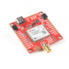
Dialog ULP WiFi DA16200 R3 Shield Hookup Guide
October 7, 2021
MicroMod WiFi Function Board - DA16200 Hookup Guide
November 11, 2021
For more information using the AT Commands, please check out the following resources
Demos
Here are a few webinar demonstrations from Arm, utilizing the DA16200 module with AT commands:
Hardware Assembly
Programming
The USB connection is utilized for programming, serial debug interface, and AT commands. Users only need to plug their DA16200 Thing Plus into a computer using a USB-C cable. Users will then be able to interact with the DA16200 module through a serial terminal.

Headers
The pins for the DA16200 Thing Plus are broken out to 0.1"-spaced pins on the outer edges of the board. When selecting headers, be sure you are aware of the functionality you need. If you have never soldered before or need a quick refresher, check out our How to Solder: Through-Hole Soldering guide.

The Feather Stackable Header Kit is a great option as it allows users to stack shields (w/ Feather footprint) or it can be placed on the a breadboard; while, the pins are still accessible from the female/male headers.
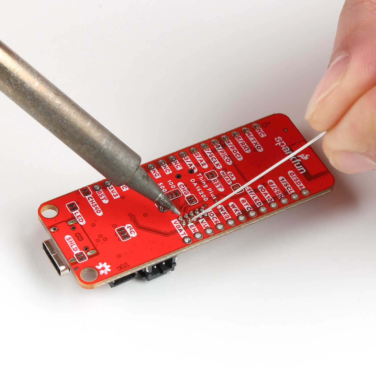
JTAG Header
If users wish to connect a debugger/programmer, they will need to solder a JTAG header. (Depending on the debugger/programmer customers utilize, an adapter may be necessary.)
Battery
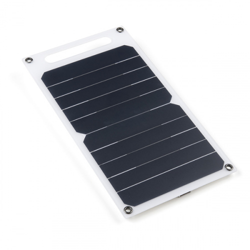
For remote applications, the DA16200 Thing Plus can be powered through its 2-pin JST battery connector. Additionally, users may be interested in utilizing a solar panel and USB-C cable to recharge their battery.
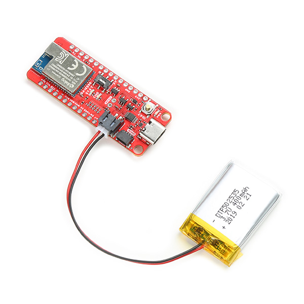
The SparkFun Thing Plus - DA16200 with a battery attached. (Click to enlarge)
Note: DO NOT remove batteries by pulling on their wires. Instead, it is recommended that pair of dikes (i.e. diagonal wire cutters), pliers, or tweezers be used to pull on the JST connector housing, to avoid damaging the battery wiring.
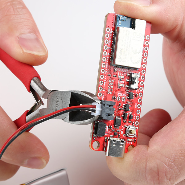
Using a pair of dikes to disconnect a battery. (Click to enlarge)
Qwiic Devices
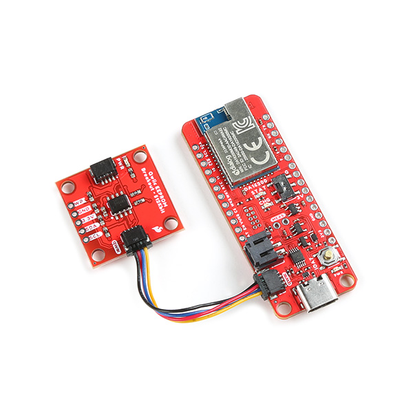
The Qwiic system allows users to effortlessly prototype with a Qwiic compatible I2C device without soldering. Users can attach any Qwiic compatible sensor or board, with just a Qwiic cable.
Example: Serial Debug Interface
The serial debug interface provides users with a console to access many of the basic functions of the DA16200MOD, such as provisioning the WiFi connection or uploading new firmware. Once users have connected their board to their computer, they will need to open a serial terminal can connect to the DA16200MOD module's serial debug interface. The terminal serial port should be configured for 230400 bps (8-N-1):
- Baud Rate: 230400 bps
- Data Bits: 8
- Parity: None
- Stop Bits: 1
- Flow Control (HW/SW): None
- If the COM port isn't available, make sure that the driver for the CH340 is installed.
- If users don't see a splash screen or
[/DA16200] #prompt, try hitting the Enter (or Return) key. - Otherwise, double check that the RTC switch is in the
3Vposition.
WiFi Configuration
Follow the instructions below, to configure the WiFi connection to the DA16200 Thing Plus:
- From the
[/DA16200] #prompt, entersetup. - Users will then be prompted
Stop all services for the setting. Are you sure ? [Yes/No] :.- Select yes, by returning
y.
- Select yes, by returning
- After, country code list will be displayed and users will be prompted for their country code.
- Users that live in the USA should enter
usfor their country code.
- Users that live in the USA should enter
- Users will then be prompted to select a WiFi mode.
- Select
1to configure the DA16200 Thing Plus for station mode.
- Select
- A list of available networks will then be displayed and users will be prompted to select an option.
- Users should enter the number of the network, which they would like to use.
- Users will be prompted if they want to set advanced WiFi configuration.
- Enter
nto skip this step.
- Enter
- The WiFi connection settings will be displayed and users will be asked to confirm the configuration.
- If the settings are correct, enter
yto confirm the configuration.
- If the settings are correct, enter
- Users will be asked to select a connection type.
- Enter
ato select an automatic DHCP IP address.
- Enter
- Users will be prompted to confirm the configuration.
- Enter
yto confirm the configuration.
- Enter
- Lastly, users will be prompted about the
SNTP ClientandDialog DPM (Dynamic Power Management).- Enter
nfor both of these options.
- Enter
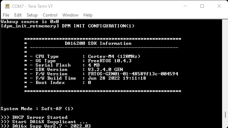
Once completed, the DA16200 will automatically reboot. After the splash screen, users should see a statement declaring that the board is in station mode (System Mode : Station Only (0)), which is eventually followed by a print out of information about the WiFi connection.
Upload New Firmware
Follow the instructions below, to upload new firmware to the DA16200 Thing Plus:
- From the
[/DA16200] #prompt, enterresetto enter the MROM command mode. - Another splash screen will be displayed followed by the
[MROM] #prompt. - To specify the memory location of where the new firmware is uploaded to the DA16200MOD, use the
loadycommand.- For the second bootloader firmware image (
FBOOT), use theloady bootorloady 0command. - For the main firmware image (
FRTOS):- Use the
loady 23000command (for slot 1). - Use the
loady 1e2000command (for slot 2).
- Use the
- For the second bootloader firmware image (
- Upload the new firmware using Y-Modem.
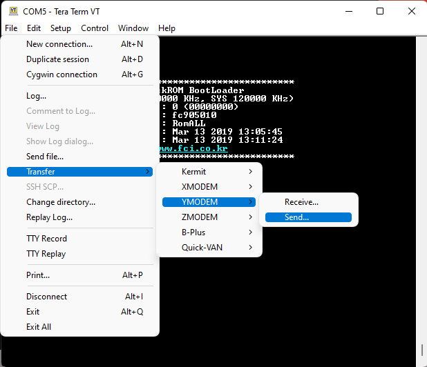
- For Windows Tera Term:
- From the File menu, select Transfer > YMODEM > Send.
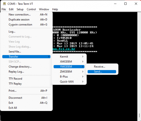
- Navigate to where the firmware image is stored, choose the required firmware image and start the download.
- From the File menu, select Transfer > YMODEM > Send.
- For Linux
minicom:- Press Ctrl+A+S and select
ymodemfrom the menu. - Navigate to where the firmware image is stored, choose the required firmware image and start the download.
- Press Ctrl+A+S and select
- For Windows Tera Term:
Example: DA16200 FreeRTOS SDK
For instructions on getting started with the Dialog DA16200 FreeRTOS SDK, setting up the development environment, and building the example projects, check out our getting started tutorial:
Getting Started with the DA16200 FreeRTOS SDK
September 15, 2022
STNP Sever
The Simple Network Time Protocol (SNTP) is as an Internet Protocol (IP) used to synchronize the clocks of networks of computers. In the DA16200 FreeRTOS SDK, there is an example project (apps > common > examples > ETC > Cur_Time) to access the Windows SNTP server and return the current time. Below are the prebuilt images for the Cur_Time example project, using version 3.2.4.0 of the SDK:
Once uploaded, if the WiFi connection has been provisioned, the board will print out the current time at regular intervals. At longer intervals, the current time will be updated from the Windows STNP server.
Build Project
To build the project, users should modify the following lines of code from the cur_time_sample.c file:
- Line 44:
TEST_SNTP_RENEW_PERIOD- Sets how often the board pulls the current time from SNTP server (seconds)
- Line 45:
TEST_TIME_ZONE- Sets the user/board's time zone (GMT)
- Example:
(-6 * 3600)represents GMT-6 or GMT (-6 hrs)
- Line 49:
CUR_TIME_LOOP_DELAY- Sets how often the current time is reported in the serial debug interface (seconds)
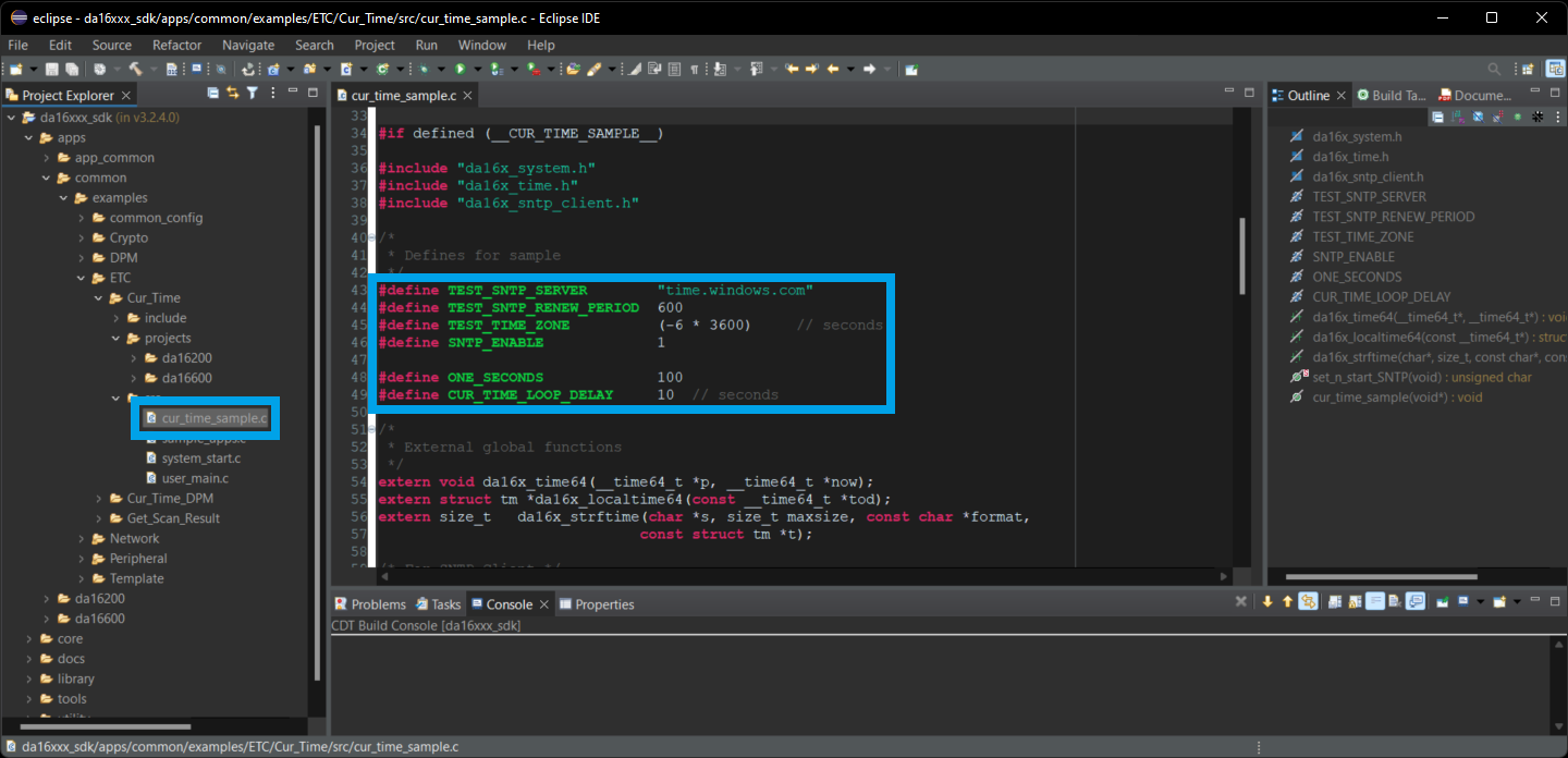
cur_time_sample.c file and the lines to modify in the Eclipde IDE. (Click to enlarge) Once the cur_time_sample.c file has been modified to suit the users needs, the example project can be imported and built in the Eclipse IDE. Users can then use the serial debug interface to upload the new firmware to the board. After users reboot the DA16200MOD module, the new firmware should run automatically. However, if the WiFi settings haven't been provisioned, users will need to configure the WiFi connection before the firmware starts outputting time stamps.

Cur_Time example after the WiFi has been provisioned. (Click to enlarge) OTA Firmware Update
The OTA (over the air) update example, allows users to update the firmware of the board by hosting the FRTOS image on a server. Through the WiFi connection, the board performs a simple HTTP request for the new firmware image. If the new image meets certain criteria, the board will download the firmware to a FRTOS slot in the SFlash memory and reboot that board to use that image.
Users can find the OTA update example project in the DA16200 FreeRTOS SDK (apps > common > examples > Network > OTA_Update). Below are the prebuilt images for the OTA_Update example project, using version 3.2.4.0 of the SDK:
Build Project
To build the project, users should modify the following lines of code from the ota_update_sample.c file:
- Modify line 52 to enable the OTA firmware update
#define SAMPLE_UPDATE_DA16_FW
- Modify line 60 with the address of the new firmware
static char ota_server_uri_rtos[256] = "https://sfecdn.s3.amazonaws.com/DA16200_FRTOS-GEN01-01-48589f13c-005000.img";
- Modify line 115 to reboot with the new firmware
g_ota_update_conf->auto_renew = 1;

ota_update_sample.c file and the lines to modify in the Eclipde IDE. (Click to enlarge) Once the ota_update_sample.c file has been modified to suit the users needs, the example project can be imported and built in the Eclipse IDE. Users can then use the serial debug interface to upload the new firmware to the board. After users reboot the DA16200MOD module, the new firmware should run automatically. However, if the WiFi settings haven't been provisioned, users will need to configure the WiFi connection before the new firmware can be downloaded and updated. The new firmware that is uploaded to the S3 bucket, toggles the GPIO pins, including GPIOA11 for the status LED.
Troubleshooting Tips
We have also included some troubleshooting tips, below, for issues that users may come across.
- One of our employees compiled a great list of troubleshooting tips based on the most common customer issues. This is the perfect place to start.
- Users looking for support on general FreeRTOS questions, can click on this link. There users can get started with posting a topic in FreeRTOS forum.
- Users looking for support with the DA16200 SDK specifically, should post their topic on RenesasRulz forum.
Sleep Mode Current
The DA16200 module can be put into various sleep modes to reduce the power consumption of the module. However, when measuring the current draw with the MEAS jumper, users may notice a current consumption up to 10 mA. This is largely attributed to the 7 mA operational current for the CH340 UART-to-Serial converter IC. The remaining 2-3 mA are consumed by the pull-up/down resistors and LEDs.
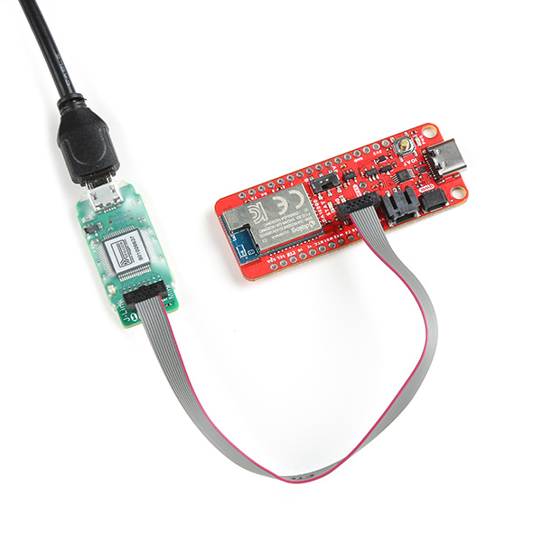
Serial Terminal Frozen
We have found that users could accidentally upload code, which may not function properly and potentially bog down the serial terminal; impeding it from taking inputs. If this occurs, users will need to use the J-Link programmer to program the module (with "known good" code) through the JTAG pins.
Reset
The reset button on this board doesn't cause the module to restart the firmware operation; it is used to reset the DA16200 module to the factory setting/configuration (when held down for +5 seconds). In order to reset the firmware, users can use the following commands in the serial debug interface:
reboot- This command will cause the module to restart the firmware execution.reset/bootreset- This command will take users to theMaskROMmode.boot- From theMaskROMcommand mode, this command will cause the module to restart the firmware execution.
OTA Update Example
With the OTA firmware update example, users may need to erase the firmware or swap which firmware image is currently running.
Erase the Firmware
When utilizing the OTA example, users may need to erase the firmware. This can be performed through the Net command mode.
- From the
[/DA16200] #prompt, enternetto enter the NET command mode. - From the
[/DA16200/NET] #prompt, enter theota_update infocommand to display the firmware information from the SFLASH memory - Users can then use the
ota_update erase_sflash <start> <size>command to erase a section of the 4MB SFLASH memory.- Example: To remove the firmware operating in the
RTOS #1section (0x1e2000) with 117268 bytes of memory, users will use the commandota_update erase_sflash 0x1e2000 117268
- Example: To remove the firmware operating in the
Boot Index
There are two slots, in which the main firmware image FRTOS can be stored in the SFLASH memory. These locations are at RTOS #0 (0x23000) and RTOS #1 (0x1e2000). Through the serial debug interface, users can specify which firmware image that the board boots up with.
- From the command console, the boot index can be changed using the
boot_idxcommandboot_idx 0- setsRTOS #0as the firmware to bootboot_idx 1- setsRTOS #1as the firmware to boot
- After running the
boot_idxcommand, run therebootcommand to boot the firmware that was selected.
Boot Failures
During the development process, there may be times when there is an error in the code or a problem downloading the firmware which could cause the DA16200/600 to fail to boot properly.
Please refer to Appendix D of the DA16200 FreeRTOS Getting Started Guide.
Resources and Going Further
For more information on the DA16200 Thing Plus and the DA16200 FreeRTOS SDK, check out the links below:
- Schematic
- Eagle Files
- Board Dimensions
- DA16200MOD Datasheet (v3.1)
- Getting Started with the DA16200 FreeRTOS SDK Tutorial
- FreeRTOS Homepage
- DA16200 FreeRTOS SDK (v3.2.2.0) (from Dialog website)
- Getting Started Guide (v1.2)
- Programming Guide (v1.5)
- GitHub Hardware Repo