Digital Temperature Sensor Breakout - AS6212 (Qwiic) Hookup Guide
 QCPete,
  El Duderino
Arduino Examples
The SparkFun AS6212 Arduino Library includes ten examples to showcase the various capabilities and settings of the AS6212. In this section we'll take an in-depth look at most of those examples and highlight pertinent bits of code where necessary. The examples build on each other so it may help to go through them in sequential order.
Prior to uploading the examples, let's take a quick look at the setup function used in all examples:
language:c
if (sensor.begin() == false)
{
    Serial.println("AS6212 Qwiic failed to respond. Please check wiring and possibly the I2C address. Freezing...");
    while (1);
};
After uploading any of the examples, open the Arduino serial monitor with the baud set to 115200. If the AS6212 fails to initialize on the bus, the code freezes and prints out "AS6212 Qwiic failed to respond. Please check wiring and possibly the I2C address. Freezing...".
If you see this message, check the connection between the breakout and controller and make sure the AS6212 is either set to the default address or the sensor.begin(); function is adjusted to the correct address. Refer to Example 2 - Different I2C Address for a quick demonstration of initializing the AS6212 on an alternate address.
Each example also includes a quick call of the setDefaultSettings(); function to return the AS6212 to default settings as adjustments to the CONFIG register (e.g. conversion cycle time, interrupt mode, alert pin polarity) remain through power cycles.
Example 1 - Basic Readings
The first example in the library demonstrates how to initialize the AS6212 on the I2C bus and retrieve temperature data from the sensor in both °C and °F. Open the example by navigating to File > Examples > SparkFun AS6212 Arduino Library > Example_01_BasicReadings. Select the appropriate Board and Port and click upload. Assuming the upload was successful, open the serial monitor with the baud set to 115200.
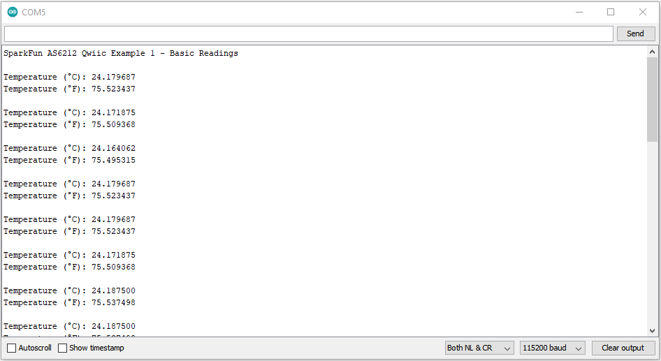
After initializing, the code prints out temperature data recorded by the AS6212 in both °C and °F every second. Try breathing on the sensor or gently press your finger to it and watch the temperature data change.
Example 3 - Sleep
Example 3 demonstrates how to put the AS6212 in and out of Sleep Mode with default settings. Note, this example keeps the default settings so the AS6212 measures in continuous mode when awake. Take a look at the next example for use of the Single Shot readings for maximum power efficiency.
The main loop creates a wake/sleep loop with a 150ms delay after waking to ensure temperature current and accurate temperature data. Without this delay the first values read will be from the last time the AS6212 was awake. Once woken up, the code returns temperature data for both Celsius and Fahrenheit and then puts the AS6212 back into Sleep Mode for five seconds.
Example 4 - Single Shot Readings
Example 4 builds on the previous example to combine Sleep Mode with Single Shot readings to maximize power efficiency. The example starts similarly to Example 3 but includes an extra two lines in the setup to start with the AS6212 in Sleep Mode to enable Single Shot readings.
language:c
sensor.sleepModeOn();
delay(150);
With the sensor in Sleep Mode, the code triggers a Single Shot reading. Note, this automatically returns the AS6212 to sleep mode once complete.:
language:c
sensor.triggerSingleShotConversion();
The code also includes a serial print to let the user know when a Single Shot conversion is ongoing and prints out the temperature data in both Celsius and Fahrenheit for each reading.
Example 5 - Alert
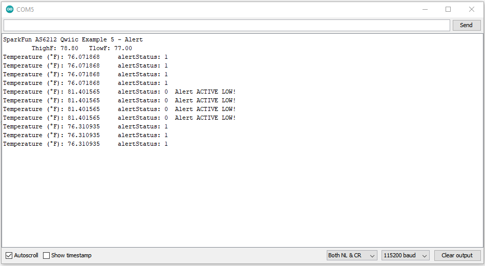
Example 5 shows how to set upper and lower temperature thresholds and how to enable/disable the Alert pin when the recorded temperature crosses those values. The code starts by checking to make sure the AS6212 is awake in case it was left in Sleep Mode from a previous example in this library. After checking that (and waking the sensor up if it was asleep), the code sets values for THighF(); and TLowF(); to 80°F and 77°F, respectively.
language:c
if (sensor.getSleepMode() == true)
{
    Serial.println("Sensor was asleep, waking up now");
    sensor.sleepModeOff();
    delay(150);
}

sensor.setTHighF(80);
sensor.setTLowF(77);
THigh and TLow thresholds have a specific resolution so you may notice that the code prints out a value slightly off of what was set for the threshold. Refer to section 6.2.9 in the AS6212 Datasheet for more specific information on the High and Low Limit Registers.
The code sets these values close together specifically to easily test the threshold settings by breathing on the sensor lightly to raise the temperature above the threshold. The main loop prints the temperature data and watches the alert status. When the temperature crosses the THigh threshold, the Alert pin goes LOW and remains LOW until the temperature drops below the TLow threshold. The code also prints out the status of the Alert pin.
language:c
void loop() {
    tempF = sensor.readTempF();
    Serial.print("Temperature (°F): ");
    Serial.print(tempF, 6);              //Reads out 6 characters of the temperature float

    alertStatus = sensor.getAlertStatus();

    Serial.print("\talertStatus: ");
    Serial.print(alertStatus);

    if (alertStatus == false) // be default alertStatus is active low
    {
        Serial.print("\tAlert ACTIVE LOW!");
    }

    Serial.println();
    delay(1000);
}
Example 6 - Conversion Cycle Time
Now that we've used the high and low temperature thresholds to toggle the Alert pin, Example 6 shows how to adjust the conversion cycle time for Single Shot measurements to alter how long the temperature must stay above/below the set temperature thresholds to trigger the Alert pin. The example sets the conversion cycle time to once every four seconds while reading the alert status every second. With this setting, the temperature data must cross the threshold and stay there through the conversion before the Alert pin will fire.
language:c
sensor.setConversionCycleTime(AS6212_CONVERSION_CYCLE_TIME_4000MS);
Other options for this setting are 125MS (8 times/sec), 250MS (4 times/sec) and 1000MS (1 time/sec). The main loop performs the same alertStatus check as the previous example and if the temperature crosses the THigh threshold and stays there during the conversion cycle time, the alert pin will go LOW until the temperature drops below the TLow threshold and stays there through a conversion cycle.
Example 7 - Consecutive Faults
Further building on the alert examples, Example 7 demonstrates how to integrate the setConsecutiveFaults function into monitoring temperature data to trigger the Alert pin. Adding a consecutive fault check on top of the conversion cycle time setting allows you to really configure how long temperature must remain above/below the THigh and TLow thresholds to trigger the Alert pin. This example sets both the setConsecutiveFaults and setConversionCycleTime to their max values so the temperature must remain above the THigh threshold for 16 seconds for the Alert pin to go LOW. Note, this also means the Alert pin will remain LOW until the temperature data is below the TLow threshold for 16 seconds as well.
language:c
sensor.setConsecutiveFaults(4);
Allowable values for the setConsecutiveFaults function are 1,2,3 or 4. The main loop is the same as the previous two examples; temperature data prints and alertStatus is checked every second. If the temperature crosses the THigh threshold and stays there for four conversion cycles (16 seconds), the code prints "Alert ACTIVE LOW!" until the temperature drops below the TLow threshold for the same duration.
Example 8 - Interrupt Mode
Example 8 shows how to use the setInterruptMode function to switch between Comparator and Interrupt. The previous examples all use the default mode, Comparator, where the Alert pin changes state when temperature data crosses the THigh threshold and stays in the new state until the temperature drops below the TLow threshold. This example sets the Alert pin to operate in Interrupt mode:
language:c
sensor.setInterruptMode(AS6212_MODE_INTERRUPT);`
In Interrupt mode, the Alert pin changes state quickly when the temperature crosses the THigh threshold and again when the temperature drops below the TLow threshold. This change is extremely quick so it works best when connected to a hardware interrupt pin on a microcontroller (see Example 10 for that use case). This example sets the Conversion Cycle time and Consecutive Faults to their lowest values to reduce any delays in reading temperature since the Alert state changes so quickly.
language:c
sensor.setConversionCycleTime(AS6212_CONVERSION_CYCLE_TIME_250MS);
sensor.setConsecutiveFaults(1);
The code prints out the Alert status and temperature when the Alert pin is fired and also includes an extra function to blink the LED to show the code is alive and working. This function exists outside of the main loop to eliminate any delays.
THigh threshold and again when the temperature data crosses the TLow threshold. This means even if the temperature data crosses the THigh threshold multiple times, the Alert pin changes state only once until the temperature data crosses below the TLow threshold. For more information, refer to section 6.2.5 and Figure 19 in the AS6212 Datasheet.
Example 10 - Hardware Interrupt
To round out the Alert pin examples (and this section), Example 10 shows how to use the Alert pin as an external hardware interrupt to your RedBoard/Arduino. Example 10 performs nearly identically to Example 9 where the Alert pin operates in Interrupt mode. The primary difference here is the code attaches an external interrupt to D2 on the RedBoard/Arduino:
language:c
attachInterrupt(digitalPinToInterrupt(2), ISR_alert, FALLING);
The example does not run any routines or actions when the interrupt pin triggers so it's left to the user to include the necessary code to run an action on interrupt. Use the interrupt to trigger an external component like a fan to cool down a temperature-sensitive device or an LED to indicate a temperature fault.