Dot/Bar Display Driver Hookup Guide
 jimblom
Example Hookup - Simple Dot/Bar Display
On this page, we'll go over a very simple, single IC, 10 LED hookup. This will show you how to set the LED current, the divider voltage, and how to select between dot or bar display mode.
This circuit will work for both an LM3914 and LM3916. The only difference will be the of analog voltages required to turn on each of the LEDs.
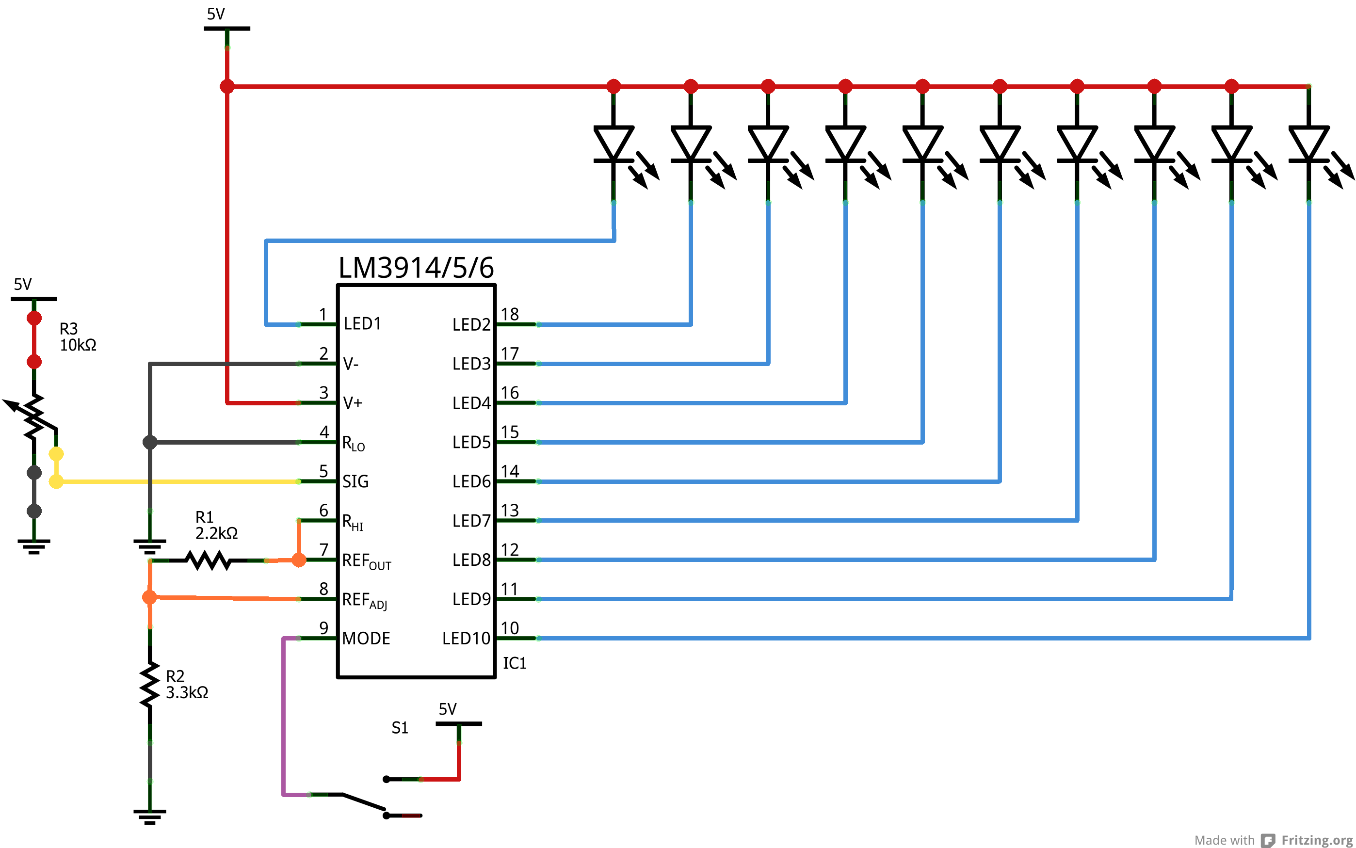
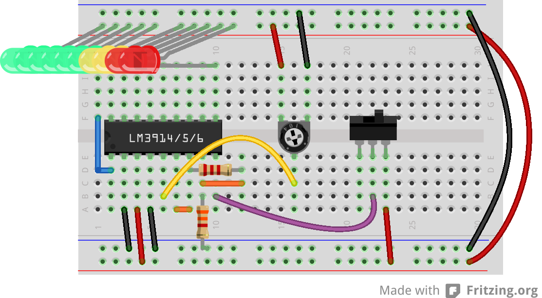
Breadboard and Schematic View
Here are a pair of diagrams that detail this simple layout. We'll assume the circuit is powered by 5V. If your supply voltage is different, some resistor values may need to change (see further below).
The analog input in this example is a potentiometer, which is good for testing, but boring otherwise. Feel free to substitute that for any analog sensor, or even an audio signal from a microphone or stereo.
The switch can be used to swap between dot or bar mode. If the mode pin is pulled high, the IC will be in bar mode. If that pin is left floating, the display works in dot mode.
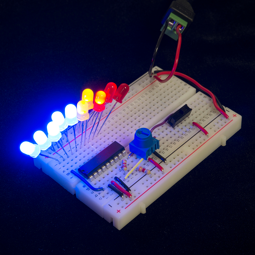
Finally, the LEDs. Pick any combination of color or size that you like. These 10-output LED drivers are perfect for the 10-Segment Bar Graph LEDs. Or you can choose a combination of any other LEDs you might have handy. 5mm LEDs are a bit too big to fit perfectly into this breadboard hookup, so you may have to creatively bend them to make them fit:
There is no need for current-limiting resistors, but make sure you have each LED connected in the correct direction (anode is connected to your power supply, cathode to IC pin).
There are a variety of options available for powering the display. In the example above we used a 5V Wall Wart plugged into a Barrel Jack Adapter, with a pair of wires flowing from there to the breadboard. If you are using a breadboard, the 5V/3.3V Breadboard Power Supply might make your life easier.
Setting the Reference Voltage and LED Current
The two resistors in this circuit are used to set both the current flowing through the LEDs, and the high voltage end of the voltage divider.
In this circuit, the RHI pin is tied to our reference voltage output. To calculate that voltage, knowing your two resistor values, use this equation:
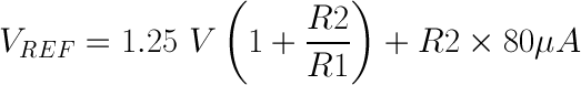
Then, knowing VREF, you can calculate the current through an LED with this equation:
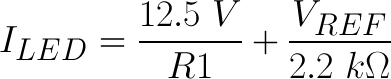
In the circuit above, where R1 is 2.2kΩ and R2 is 3.3kΩ, VREF will be about 3.4V (safely 1.5V under the supply voltage). ILED will be about 7.2mA -- a happy, medium current for most LEDs.
If you need to pick a wider or smaller range, you'll have to play with those resistor values, but the equations should hold true.