Easy Driver Hook-up Guide
 Toni_K
Hardware Overview
The Easy Driver is designed by Brian Schmalz, and is designed around the A3967 IC. This IC enables you to drive bipolar stepper motors that are 4, 6, or 8-wire configurations. The board can either work with 3.3V or 5V systems, making it extremely versatile. Two mounting holes on-board give the user the option to mechanically stabilize the Easy Driver.
Pin Descriptions
Let's take a look at all of the pins broken out from the A3967 IC on the Easy Driver.
Board Top Pins
If you look across the top of the board, you will see several pins.
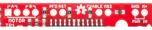
They function as follows:
- Coil A+ - H-Bridge 2 Output A. Half of connection point for bi-polar stepper motor coil A.
- Coil A- - H-Bridge 2 Output B. Half of connection point for bi-polar stepper motor coil A.
- Coil B+ - H-Bridge 1 Output A. Half of connection point for bi-polar stepper motor coil B.
- Coil B- - H-Bridge 1 Output B. Half of connection point for bi-polar stepper motor coil B.
- PFD - Voltage input that selects output current decay mode. If PFD > 0.6Vcc, slow decay mode is activated. If PFD < 0.21Vcc, fast decay mode is activated. Mixed decay occurs at 0.21Vcc< PFD < 0.6Vcc.
- RST - Logic Input. When set LOW, all STEP commands are ignored and all FET functionality is turned off. Must be pulled
HIGHto enable STEP control. - ENABLE -Logic Input. Enables the FET functionality within the motor driver. If set to
HIGH, the FETs will be disabled, and the IC will not drive the motor. If set toLOW, all FETs will be enabled, allowing motor control. - MS2 -Logic Input. See truth table below for HIGH/LOW functionality.
- GND - Ground.
- M+ - Power Supply. 6-30V, 2A supply.
Bottom Board Pins
There are also pins across the bottom of the board. Their functions are described below.
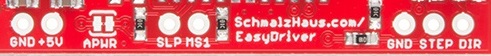
- GND - Ground.
- 5V -Output. This pin can be used to power external circuitry. 70mA max is required for Easy Driver functionality.
- SLP - Logic Input. When pulled
LOW, outputs are disabled and power consumption is minimized. - MS1 - Logic Input. See truth table below for HIGH/LOW functionality.
- GND - Ground.
- STEP -Logic Input. Any transition on this pin from
LOWtoHIGHwill trigger the motor to step forward one step. Direction and size of step is controlled by DIR and MSx pin settings. This will either be 0-5V or 0-3.3V, based on the logic selection. - DIR -Logic Input. This pin determines the direction of motor rotation. Changes in state from
HIGHtoLOWorLOWtoHIGHonly take effect on the next rising edge of the STEP command. This will either be 0-5V or 0-3.3V, based on the logic selection.
| MS1 | MS2 | Microstep Resolution |
|---|---|---|
| L | L | Full Step (2 Phase) |
| H | L | Half Step |
| L | H | Quarter Step |
| H | H | Eigth Step (Default configuration) |
Solder Jumpers
There are two solder jumpers on board. These provide the following features to the user:
- 3/5V - This jumper allows the user to set the configuration of VCC between 3.3V or 5V. With the jumper open, VCC will be 5V. If the jumper is closed, VCC is 3.3V.

- APWR - This jumper allows the user to source Vcc on the 5V/GND pins to external hardware.

Potentiometer
The potentiometer on board is included to allow users the ability to select the max current provided to the motor. It ranges from 150mA to 750mA. This will require you to be aware what current range your motor can handle -- check the motor’s data sheet for the current settings.
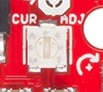
If you can’t find this information, have no fear – you can still find the proper setting for the potentiometer. First, set it to the lowest setting of the potentiometer. Keep in mind that the potentiometer is delicate, so be careful to not force the potentiometer past the mechanical stops when turning it. Once you have the motor being driven at a slow, yet steady speed, slowly turn the potentiometer and pay attention to the motor’s behavior. You should find a sweet spot where the motor doesn’t skip or jerk between steps.