EL Sequencer/Escudo Dos Hookup Guide
 Toni_K
Hardware Overview - Comparison
This section will cover the features that are shared between both the EL Sequencer and the EL Escudo Dos.
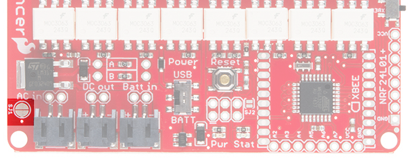
External Power Headers
The EL Sequencer and Escudo Dos have ports for power.
 |
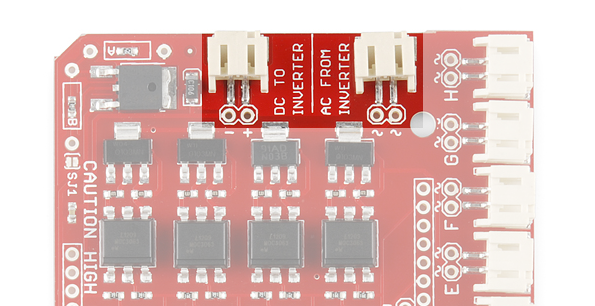 |
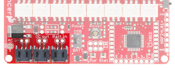
| External Power Headers on the EL Sequencer | External Power Headers on the EL Escudo Dos |
There are three power connection points on the Sequencer. The first is the AC In connection, which is the default connection point for any external inverter. The second connection is the DC Out line, which will connect to any inverter that does not have an external power supply. This provides a DC power supply to the inverter from the EL Sequencer itself. The final power connection is the Batt In connection. This allows the user to provide a power supply from a 3.7V lipo battery, or other power supply of 3.5V-16V.
These can be connected via a standard 0.1" 2-pin header, or via the JST connector available on each line. If you ever forget the purpose of these connections, they are clearly labeled on the bottom of the board. The power headers on the EL Escudo Dos have the same functionality as the EL Sequencer. However, there is no Batt In header. This is because the power for the Escudo comes from the VRAW line on the connected Arduino or RedBoard.
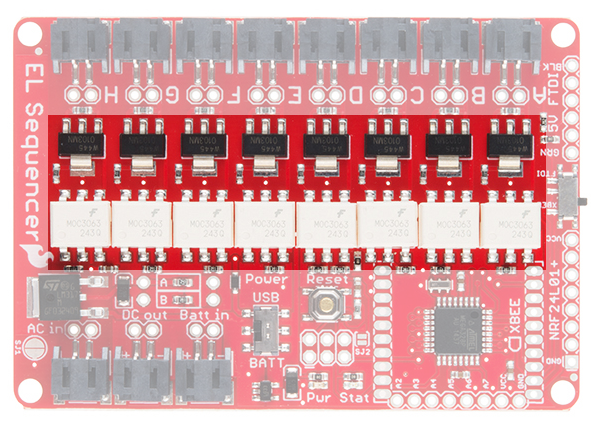
Channel Headers (HIGH VOLTAGE)
 |
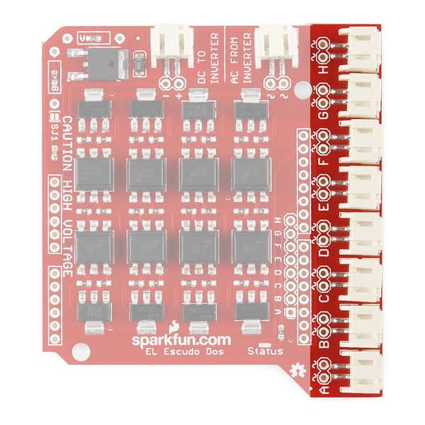 |
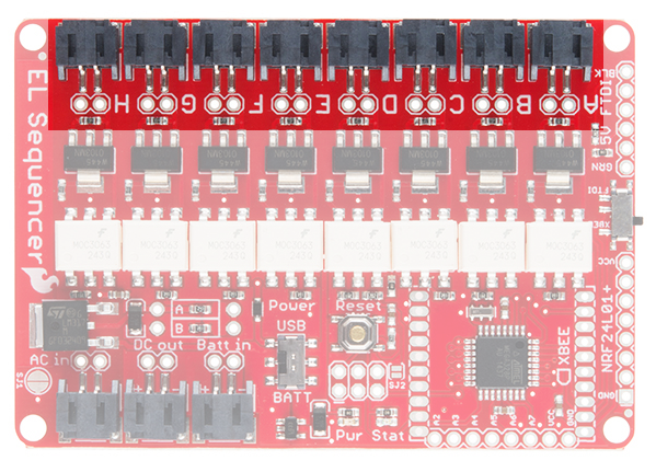
| EL Sequencer Channel Headers | EL Escudo Dos Channel Headers |
As the silk on the bottom side of the board states, there is high voltage in this area of the board. Care must be given when handling the board in a powered state, to prevent a shock to the user. These channels output the AC current needed to drive the EL wire. This is output at 100+V AC, 4000Hz (dependent on the inverter used). Each channel (A-H) is attached to one digital pin on the ATMega328 (pins 2-9, respectively). Driving the digital pins HIGH triggers the EL wire to turn on.
These can be connected to EL devices (wire, panels, etc.) via a standard 0.1" 2-pin header, or via the JST connector available on each line.
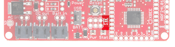
Solder Jumpers
- SJ1 - This jumper allows the user to bypass the LM317 regulator when it's shorted. This regulator is used for external inverters. If left open, the regulator output voltage can be modified by user-supplied resistors on RA and RB pads. More on that below.
 |
 |
| Solder Jumper 1 on the Sequencer. | Solder Jumper 1 on the Escudo. |
- SJ2 - This jumper is included as an option for wirelessly uploading of code to the Sequencer via XBee. This feature is experimental, and no guarantees are given for this feature's functionality.
TRIACs and Optoisolators
The main functionality of the Sequencer/Escudo comes from the TRIACs (Triode for Alternating Current) on-board. The MO3063S TRIAC Optocoupler takes the logic output from the associated ATMega328 digital pin which triggers the Z0103MN TRIAC to open the flow of the AC current from the inverter through the gate to drive the EL channel. This keeps the AC side of the circuit optically isolated from the DC portion of the circuit.
 |
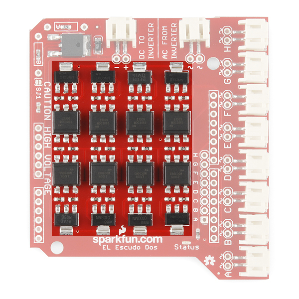 |
| EL Sequencer TRIACs and Optoisolators | EL Escudo Dos TRIACs and Optoisolators |
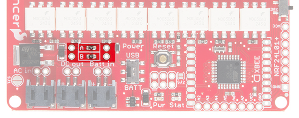
Adjustable Voltage Regulator
The LM317 voltage regulator on this board is adjustable based on the resistor values applied to it. By default, this board comes shipped with a 390Ω resistor on R1 and a 240Ω on R2. However, footprints for thru-hole resistors (A and B) have been added for the user to adjust the voltage out to their project needs. You'll need to remove the SMD resistors first. Then add thru-hole resistors of your choice. See the LM317 Datasheet for more information on which resistor values correspond to which voltage output.
 |
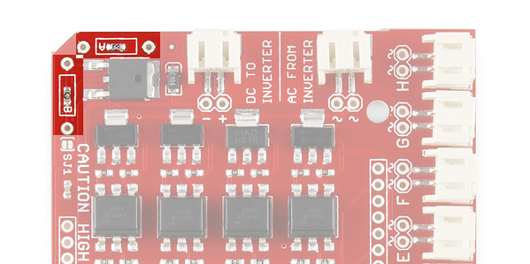 |
| Resistors A and B on the EL Sequencer | Resistors A and B on the EL Escudo Dos |