EL Sequencer/Escudo Dos Hookup Guide
 Toni_K
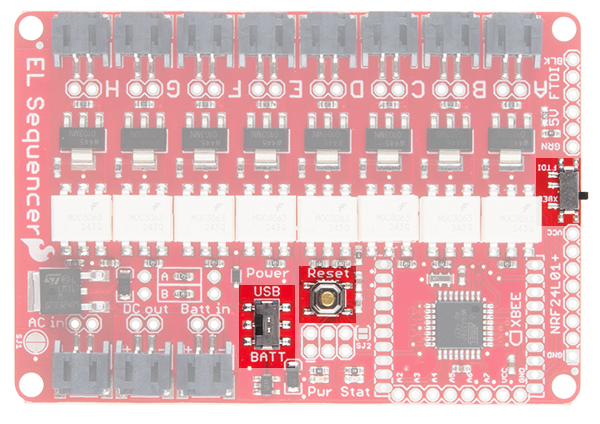
Hardware Overview - EL Sequencer
This section will cover the unique features of the EL Sequencer.
NRF24L01+ Header
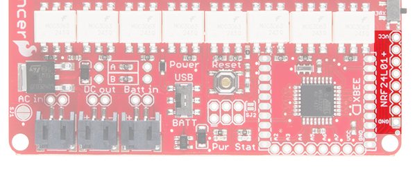
This header is designed to interface with an NRF24L01+ module breakout. This provides a 2.4GHz signal to the EL Sequencer, which provides remote control options for the Sequencer at up to a 100m range.
FTDI Header
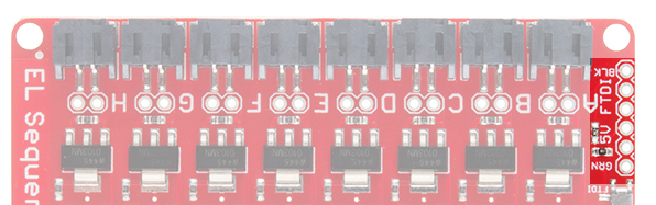
This is a 5V FTDI header, which is given to provide simple access for reprogramming the ATMega328 via serial connections. This can also be used to have the EL wire triggered via serial data in to the system.
XBee Header
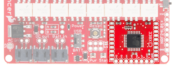
This connection is provided to give users the option of wirelessly connecting the EL Sequencer via XBee. This can be used for mesh networking of several different Sequencers together (this is great for group costume projects), or remote control of the Sequencer.
ICSP Header
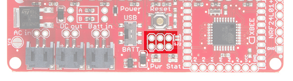
This 6-pin header is provided to allow the user to reprogram the ATMega328 on board via an external programmer. This also allows you to reprogram the EL Sequencer without the requirement of the Optiboot loader from the Arduino IDE.
Analog Input Header
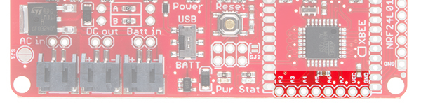
The additional analog pins on the ATMega328 are broken out to a standard 0.1" header on the EL Sequencer. This also gives the user the capability to trigger the EL wires from analog inputs (such as a photocell, temperature sensor, or a line sensor ).
Pins A6 and A7 are analog input only. Pins A0-A5 can be used as an analog input or as a digital I/O.
Switches and Reset Button
XBee to FTDI (far right, center) - This switch changes the RX line from being supplied via the FTDI header or the XBee. If attempting to program the Sequencer via FTDI, this switch must be set to the FTDI side.
USB/BATT (bottom, center) - This switch changes the power source for the ATMega328. The USB setting allows the ATMega328 to be powered via the FTDI connection, while the BATT setting allows the Arduino part to be powered off of a lipo battery instead.
Reset Button - Resets the Arduino sketch running on the ATMega328. It pulls the RESET line low, allowing the system to reset.