Electric Imp Breakout Hookup Guide
 jimblom,
  Shawn Hymel
About the imp002 Breakout
The imp002 is a solder-down module version of the original imp card. We have done the hard work of creating a breakout board for you. Now, you just need one board instead of 2 to get started with the electric imp!

We recommend you read the About the imp section to learn what is in the imp, what the Planner is, and a brief overview of the Squirrel language. Like the imp card, the imp002 module contains an embedded ARM Cortex-M3 microprocessor, an onboard WiFi module, and antenna.
The Hardware: 12 Glorious I/Os
We have broken out 12 I/O pins from the imp002 module to standard 0.1" headers. Much like the imp card, these pins can be used for a variety of functions.
| Pin # | UART1289 | UART57 | UART12 | UART6E | UARTB | I2C89 | I2C12 | SPI257 | SPI189 | DAC | ADC | PWM |
|---|---|---|---|---|---|---|---|---|---|---|---|---|
| A | Yes | |||||||||||
| B | RX | Yes | ||||||||||
| C | Yes | |||||||||||
| D | ||||||||||||
| E | RX | |||||||||||
| 1 | CTS | TX | SCL | SCLK | Yes | Yes | Yes | |||||
| 2 | RTS | RX | SDA | MISO | Yes | Yes | ||||||
| 5 | TX | SCLK | Yes | Yes | Yes | |||||||
| 6 | TX | |||||||||||
| 7 | RX | MOSI | Yes | Yes | ||||||||
| 8 | TX | SCL | MOSI | Yes | Yes | |||||||
| 9 | RX | SDA | MISO | Yes | Yes |
Powering the imp002 Breakout
The imp002 Breakout Board contains a 3.3V TPS62172 step-down regulator (and the inductor/capacitors supporting it). This regulator allows for input voltages anywhere between 3.3V and 17V (voltages in the upper end of that range may produce some heat). It can support up to 500mA of continuous current.
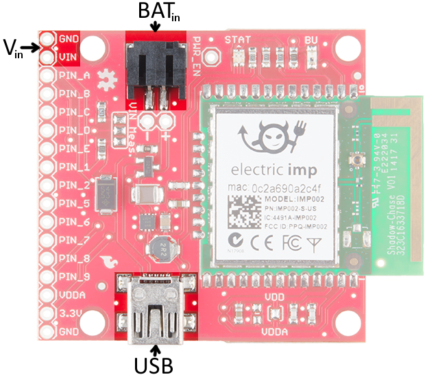
There are three power inputs on the board, all of which, are fed into the on-board 3.3V regulator:
- "VIN" header - This standard 0.1" header feeds directly into the 3.3V regulator.
- Battery input - These are the pins labeled "+" and "-" as well as the JST connector, which mates with our LiPo batteries (or AA batteries).
- USB mini-B connector - This power input should feed a clean, 5V source into the breakout board's regulator. The USB voltage supply can come from either a mini-B cable connected to your computer or a USB wall adapter.
NOTE: There is a voltage selector circuit on the imp002 Breakout Board that will automatically use whichever voltage is higher: battery or USB. Be aware that the circuit does NOT charge the battery, it just prevents current flowing back into the source with the lower voltage (i.e. a short).
The imp002 Breakout's Schematic
There are a number of circuits used to support the imp002, all of which can be found on the imp002 Breakout Board.
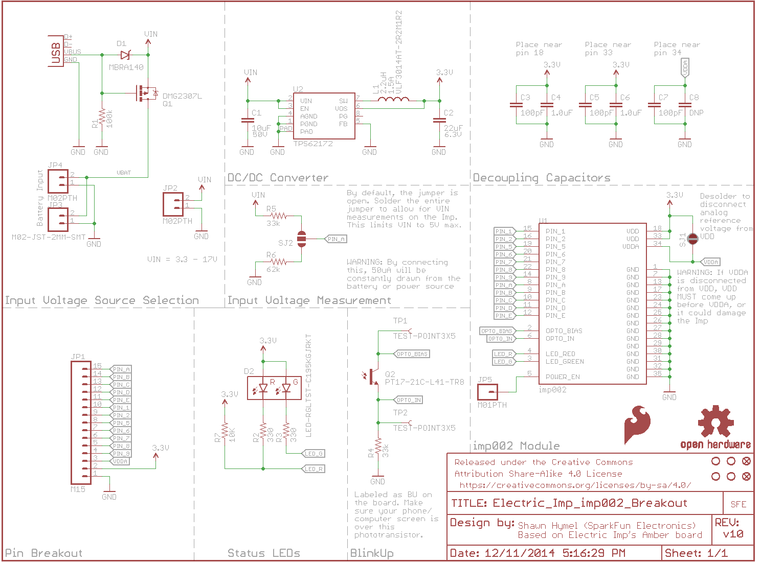
- Input Voltage Source Selection - automatically switches between USB and battery input (whichever voltage is higher)
- Pin Breakout - Power and I/O pins from the imp002 module
- DC/DC converter - the TPS62172 buck regulator and supporting components
- Input Voltage Measurement - the jumper can be soldered to allow VIN measurements on PIN A
- imp002 module - the imp module and decoupling capacitors
- Status LED - the red/green LED required by the imp to display its status (connecting, error, etc.)
- BlinkUp - Light sensor for sending WiFi credentials to the imp002 module
Pinout
All of the imp's GPIO pins are broken out to the 0.1"-spaced header, along with a few related power pins:
- GND - Common ground
- VIN - Input voltage supply fed into regulator
- PIN_A - imp002 pin A (ADC)
- PIN_B - imp002 pin B (UARTB RX, ADC)
- PIN_C - imp002 pin C (PWM)
- PIN_D - imp002 pin D
- PIN_E - imp002 pin E (UART6E RX)
- PIN_1 - imp002 pin 1 (DAC, UART1289 CTS, UART12 TX, I2C12 SCL, SPI189 SCLK, DAC, ADC, PWM)
- PIN_2 - imp002 pin 2 (UART1289 RTS, UART12 RX, I2C12 SDA, SPI257 MISO, ADC, PWM)
- PIN_5 - imp002 pin 5 (UART57 TX, SPI257 SCLK, DAC, ADC, PWM)
- PIN_6 - imp002 pin 6 (UART6E TX)
- PIN_7 - imp002 pin 7 (UART57 RX, SPI257 MOSI, ADC, PWM)
- PIN_8 - imp002 pin 8 (UART1289 TX, I2C89 SCL, SPI189 MOSI, ADC, PWM)
- PIN_9 - imp002 pin 9 (UART1289 RX, I2C89 SDA, SPI189 MISO, ADC, PWM)
- VDDA - ADC reference voltage. Connected to 3.3V by default.
- 3.3V - 3.3V output from regulator
- GND - Common ground