ESP32 Thing Motion Shield Hookup Guide
 MTaylor
Hardware Assembly
In this section, we'll prepare the shield for a development environment by adding headers. This section also shows what the GPS module, battery, and SD card look like when properly inserted.

Attach the Stackable Headers to the Motion Shield
Solder a single pin on each header. Make sure the headers are straight, and lined up. You can use perf board, or an already populated ESP32 Thing to help with alignment.
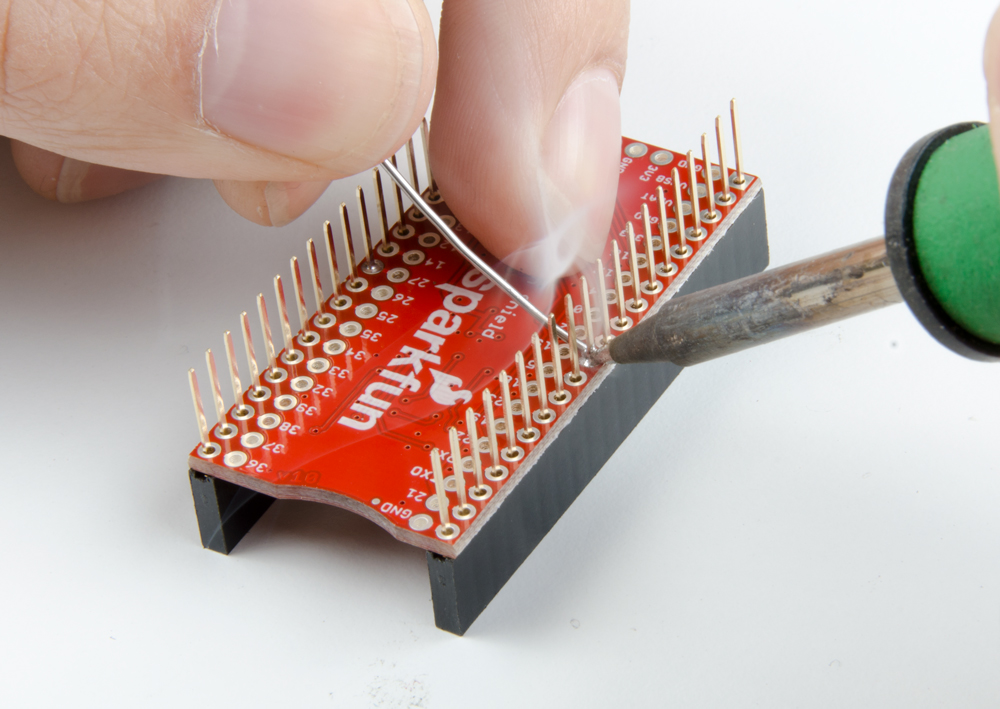
Solder the rest of the pins focusing on getting nice, even, conic fillets.

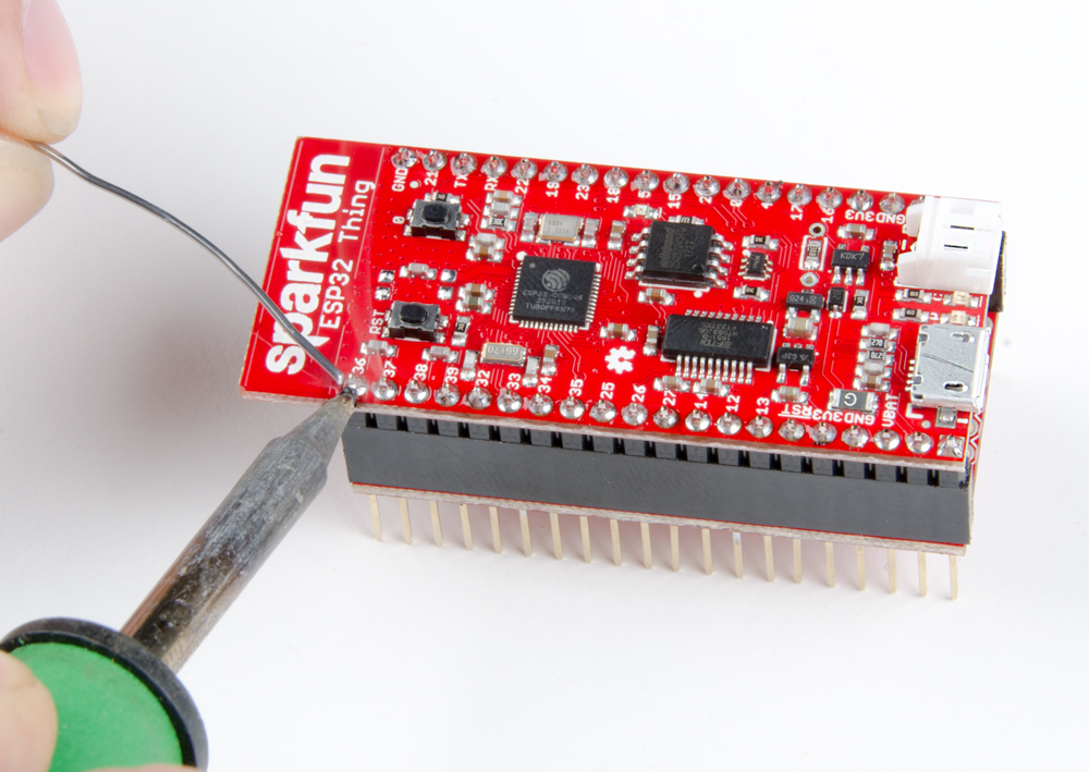
Attach the Headers to the ESP32 Thing
Put the pin headers in the shield, and set the ESP32 Thing on top. Then, apply solder and build up nice fillets making sure to not bridge any pins.
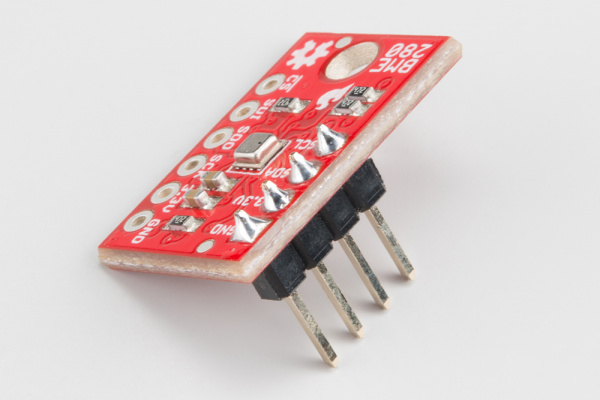
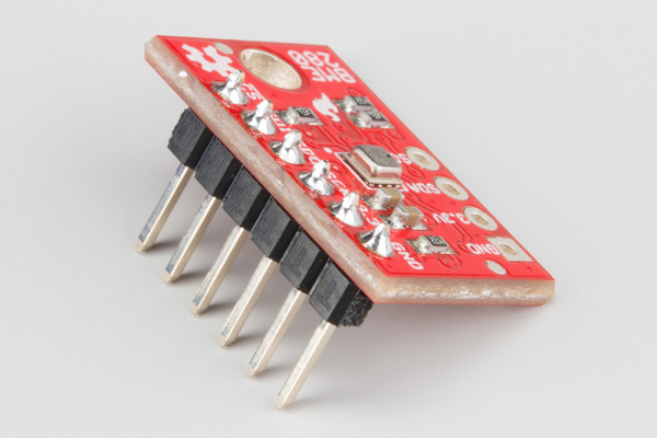
Adding an Optional Sensor
If you're using a BME280 to try out the I2C or SPI port, install headers on it as well. See the BME280 Hookup Guide for more information.
 |
 |
 |
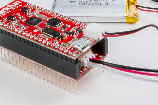
3-Pin JST and microSD Card
Make sure the JST and microSD cards are installed properly.
If the JST connectors feel like they're not going in, don't force them, try wiggling them instead. They will hang out a bit when properly seated.
The microSD card slot is dual position with click feature, and the PCB has a recess. The card should easily click in and out.
 |
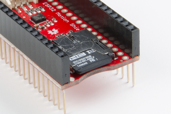 |
The JST connectors are seated properly, protruding slightly from their sockets (left). When the SD card is inserted properly (right), it should be flush with the edge of the board.
Stack and Connect Additional Parts!
Stack the ESP32 Thing on the ESP32 Thing Motion Shield.
You can also install the stack in a breadboard, letting the antenna hang off the end so you have the most room left to work with when prototyping. If using the BME280, install that on the breadboard as well and wire the sensor as explained in the "Using the I2C and SPI Buses" example.