ESP8266 Thing Hookup Guide
 jimblom
Using the Arduino Addon
If you've used Arduino in the past, there will be some new programming schemes to get used to in ESP8266 land.
Pin Mappings
As with any other Arduino, the pin mappings printed on the board match the pin you read or write to. The SDA and SCL pins can be referenced as 2 and 14 respectively.
There's only one analog input pin, labeled ADC. To read the ADC pin, make a function call to analogRead(A0). Remember that this pin has a weird maximum voltage of 1V -- you'll get a 10-bit value (0-1023) proportional to a voltage between 0 and 1V.
Yielding
This is one of the most critical differences between the ESP8266 and a more classical Arduino microcontroller. The ESP8266 runs a lot of utility functions in the background -- keeping WiFi connected, managing the TCP/IP stack, and performing other duties. Blocking these functions from running can cause the ESP8266 to crash and reset itself. To avoid these mysterious resets, avoid long, blocking loops in your sketch.
If you have a long loop in your sketch, you can add a delay([milliseconds]) call within, to allow the critical background functions to execute. The ESP8266's delay() funciton, while of course delaying for a set number of milliseconds, also makes a quick call to the background functions.
The amazing creators of the ESP8266 Arduino libraries also implemented a yield() function, which calls on the background functions to allow them to do their thing. As an example, if your sketch is waiting for someone to press a button attached to pin 12, creating a loop like this will keep the ESP8266 from crashing:
language:c
pinMode(12, INPUT_PULLUP); // Set pin 12 as an input w/ pull-up
while (digitalRead(12) == HIGH) // While pin 12 is HIGH (not activated)
    yield(); // Do (almost) nothing -- yield to allow ESP8266 background functions
Serial.println("Button is pressed!"); // Print button pressed message.
ESP8266WiFi Class
This is the ESP8266, so the WiFi class will probably be included in just about every sketch there is. If you've used the Arduino WiFi library before, the ESP8266 WiFi library will be very similar, there's just a few key differences:
- To include the ESP8266 WiFi library call
#include <ESP8266WiFi.h>not<WiFi.h>. - To connect to a network, like the normal WiFi library, call
WiFi.begin(NetworkSSID, NetworkPassword). You can also set the ESP8266 up as a WiFi access point by callingWiFi.softAP(AP_SSID, AP_Password). - To set the ESP8266's mode, which can be access point (AP), station (STA), or combo (the ESP8266 can do both at the same time!), call
WiFi.setMode([mode])with eitherWIFI_AP,WIFI_STA, orWIFI_STA_APas the parameter.
The examples earlier in this tutorial should have demonstrated all of these differences.
Libraries Available/Not Available and the Differences
A lot of the core Arduino libraries have been re-written to work for the ESP8266, including:
- Wire -- The ESP8266 should work with any I2C sensor you can throw at it -- just use the same Wire API calls you're used to. There are a few differences:
- Pin definition: The ESP2866 doesn't actually have any hardware I2C pins -- those labeled on the Thing are the default, but you can actually use any two pins as SDA and SCL. Calling
Wire.begin()will assume pins 2 and 14 are SDA and SCL, but you can manually set them to any other pin by callingWire.begin([SDA], [SCL]).
- Pin definition: The ESP2866 doesn't actually have any hardware I2C pins -- those labeled on the Thing are the default, but you can actually use any two pins as SDA and SCL. Calling
- SPI -- The ESP8266 Thing can control an SPI bus using function calls made standard by the Arduino SPI library.
- An additional function to set the frequency --
SPI.setFrequency([frequency])-- is added. You may need to call that in your setup to slow the clock down from its default value. For example,SPI.setFrequency(1000000)will set the SPI clock to 1MHz. - The MISO, MOSI, and SCLK SPI pins are hard-coded and can't be moved, they are:
- An additional function to set the frequency --
| Pin Number | SPI Function |
|---|---|
| 12 | MISO |
| 13 | MOSI |
| 14 (SCL) | SCLK |
| 15 | CS |
Using the Serial Monitor
GPIO0 -- while perfectly capable as a digital I/O -- serves a secondary purpose as a bootload/run-mode controller. When the ESP8266 boots up, it looks at GPIO0's value to either enter the bootloader or start running the current program:
| GPIO0 Value | ESP8266 Mode |
|---|---|
| HIGH (3.3V) | Run Program |
| LOW (0V) | Bootloader |
To make it easy to program the ESP8266, we've tied GPIO0 to DTR (along with RST). When your programmer begins to upload a sketch, it'll pull DTR low, in turn setting GPIO0 low and making the ESP8266 enter bootloader mode.
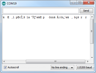
Unfortunately, when you open a serial terminal, DTR usually goes low again. So every time you open the Arduino serial monitor, it'll cause the ESP8266 to enter bootloader mode, instead of run-program mode. If you open up the serial monitor, and all you see is a line of gibberish, you've probably booted the ESP8266 into bootloader mode.
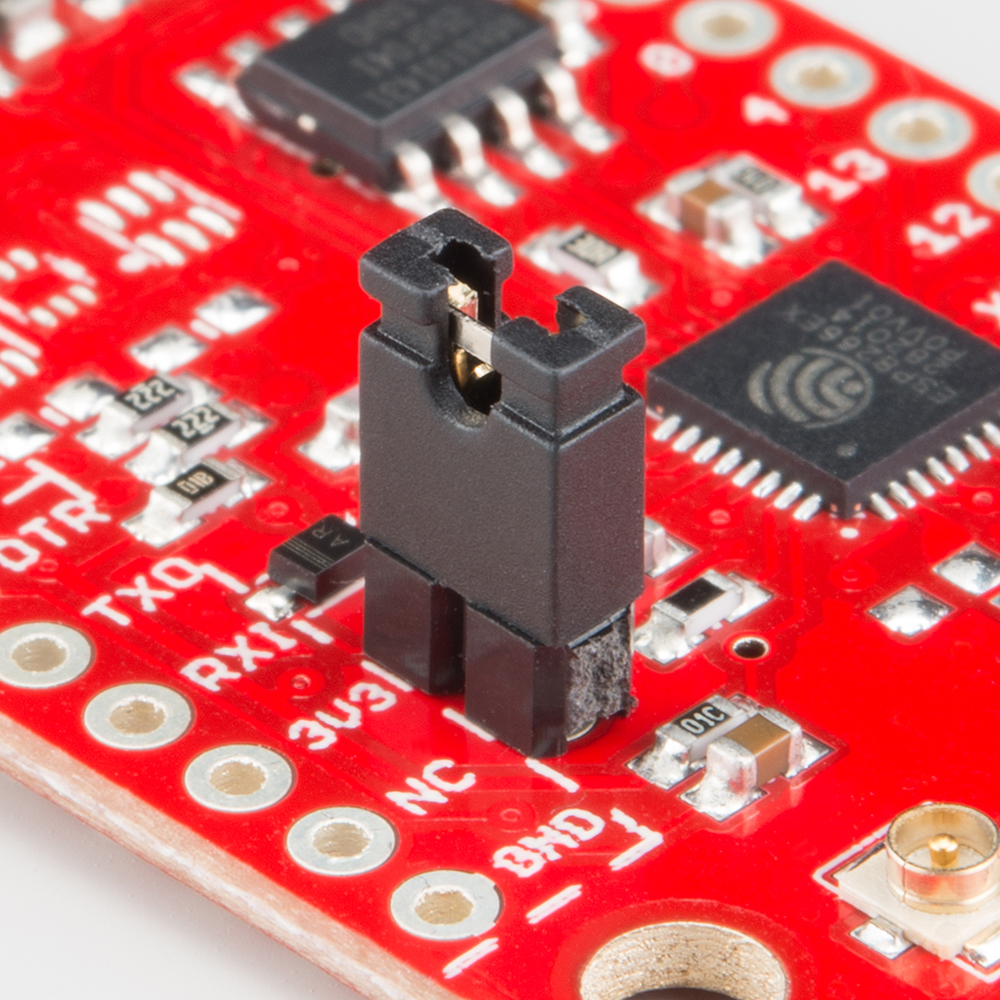
There are a few ways around this. We've added the DTR jumper on the bottom of the board. You can cut the trace on the back and install a 2-pin male header combined with a 2-pin jumper. If the jumper is present, the board will be able to be programmed. Removing the jumper will enable serial terminal mode.
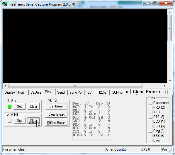
Or you can find a serial terminal program that allows control of the DTR pin directly. RealTerm allows for this control -- navigate to the "Pins" tab, and click "Clear" next to "DTR."
Unfortunately, this Windows-only solution is the only terminal program we've found so far with such control. Your best bet may be to try to avoid serial debugging whenever possible -- that's what LED's are for, right? (Tongue only kind-of in cheek.)