ESP8266 WiFi Shield Hookup Guide
 jimblom
AT Firmware Overview
While the hardware is obviously important, what really makes the WiFi Shield play nicely with an Arduino is its serial-based AT command-set firmware.
The ESP8266 WiFi Shield ships with Espressif's (the manufacturer of the ESP8266) latest release of their AT command set firmware. We've tweaked the base firmware to add support for the status LED and serial control of the ESP8266's unused I/O. Our firmware is as open source as can be (some of Espressif's source is only available as blobs) -- you can check it out in our ESP8266 WiFi Shield GitHub repository.
Using the AT Command Set
In later parts of this tutorial, we'll introduce an Arduino library, which handles all of this "AT" stuff for you. But it doesn't hurt to at least familiarize yourself with the commands used to configure the ESP8266.
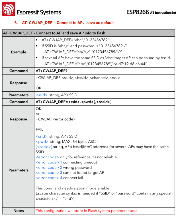
For the full list of the ESP8266's AT commands check out this document. There are a variety of commands, which configure everything from access-point names/passwords, to TCP connections, to the device's baud rate.
If you're manually entering these commands, keep in mind that the end of each command should be signaled by a carriage return then line feed ("\r\n").
As an example exercise, here are a series of commands you might type to connect a WiFi access point and get your IP address:
> AT+CWOMDE=1
    OK
> AT+CWJAP="MySSID","MyPSK"
    WIFI CONNECTED
    WIFI GOT IP
    OK
> AT+CIFSR
    +CIFSR:STAIP,"192.168.0.101"
    +CIFSR:STAMAC,"18:fe:34:9d:b7:d9"
Custom GPIO Commands
We've taken Espressif's AT command firmware and added a few additional functions which give you control over the ESP8266's unused digital GPIO. In all, there are 9 GPIO to be digitally controlled: 0, 2, 4, 5, 12, 13, 14, 15, and 16 (XPD).
The custom commands allow you to set a pin to input or output (or input with pullup resistor), digitally write high or low, or read the pin's state:
| Function | Command | Example | Notes |
|---|---|---|---|
| Pin Mode | AT+PINMODE=<pin>,<mode> | AT+PINMODE=5,o | Mode:
|
| Digital Write | AT+PINWRITE=<pin>,<state> | AT+PINWRITE=5,h | State:
|
| Digital Read | AT+PINREAD=<pin> | AT+PINREAD=0 | Response: 0 or 1 for LOW or HIGH. |