Experiment Guide for the Johnny-Five Inventor's Kit
 rwaldron
 reconbot
 D___Run___
 lyzadanger
 Shawn Hymel
Experiment 6: Reading a Light Sensor
Introduction
This isn't your first rodeo with an analog sensor—this experiment will build on what you learned in Experiment 3: Reading a Potentiometer.
In this experiment, you'll meet a new component: photoresistors. Also called photocells or Light-Dependent Resistors (LDRs), these simple sensors change resistance depending on ambient light intensity. You'll learn why you need to use an additional resistor in your circuit to be able to read values from the photoresistor. You'll build a bar graph to display changing light conditions. Then you'll make a light-sensitive nightlight.
Throughout this experiment, you'll use Johnny-Five's Light class to read data from the photoresistor, and, in multiple examples, you'll see how changing the scale of the data read from the photoresistor can be useful in further manipulating or presenting that data.
Preflight Check
Whoa there, Turbo! If this is your first experiment with the Johnny-Five Inventor's Kit (J5IK) and the Tessel 2, there are a few things you gotta do first:Suggested Reading
The following tutorials provide in-depth background on some of the hardware concepts in this experiment:
Parts Needed
You will need the following parts for this experiment:
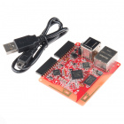
- 1x Tessel 2
- 1x Breadboard
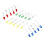
- 1x Photoresistor
- 1x Standard LED (any color is fine)
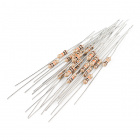
- 1x 10kΩ Resistor
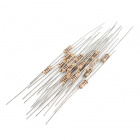
- 1x 100Ω Resistor
- 6x Jumper Wires


Introducing the Photoresistor
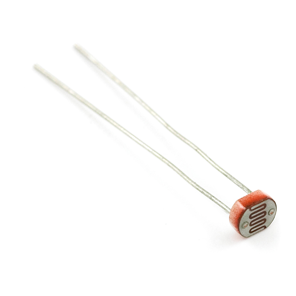
The resistance of a photoresistor changes depending on how much light is hitting it. When it's really bright, the photocell has less resistance—it's more conductive. When it's dim, the photocell has more resistance.
The resistance changes, yes, but the Tessel 2 analog input pins respond to changing voltage. Fortunately, there's a straightforward way to create a circuit that translates changes in resistance to changes in voltage: use a voltage divider.
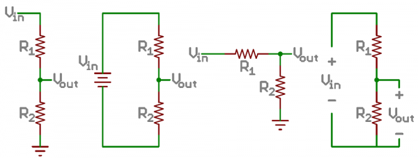
A voltage divider is a circuit that uses a pair of resistors to translate an input voltage (Vin) into different (always lower) voltage (Vout). All of the voltage that goes into the circuit has to get "used up" by the components in between the two resistors; all of the supply voltage (3.3V in our case) must be accounted for. If R1 and R2 in a voltage-divider circuit have equal resistance (say, two 100Ω resistors), the voltage at Vout will be one-half of the input voltage, or 1.15V—each gobbles up half of the voltage.
Each resistor drops its share of the supply voltage, proportional to its share of the circuit's total resistance. If R1 is 300Ω and R2 is 100Ω, Vout is one-quarter (25%) of the input voltage because three-quarters has already been snatched up by R1. See? The second resistor didn't change; it has a static resistance. Meanwhile, the changing resistance of R1 is translated into voltage changes at Vout.
In this example's circuit, the second resistor will be a 10kΩ resistor. It won't change resistance. It'll just chill. But the photoresistor—that'll change resistance as light changes, changing its proportional resistance in the context of the whole circuit. So, voila!, voltage at Vout changes, too, and we can read that using the Tessel.
The photoresistor changes its resistance based on the light to which it is exposed. To use this with the Tessel 2 board, you will need to build a voltage divider with a 10kΩ resistor as shown in the wiring diagram for this experiment. The Tessel 2 board cannot read a change in resistance, only a change in voltage. A voltage divider allows you to translate a change in resistance to a corresponding voltage value.
The voltage divider enables the use of resistance-based sensors like the photoresistor in a voltage-based system. As you explore different sensors, you will find more resistance-based sensors that only have two pins like the photoresistor. To use them with your Tessel 2 board you will need to build a voltage divider like the one in this experiment. To learn more about resistors in general, check out our tutorial on resistors and also our tutorial on voltage dividers.
Note: Make sure you are using the 10kΩ resistor in your voltage divider with the sensors in this kit. Otherwise you will get odd and inconsistent results.
Hardware Hookup
Enough reading ... let's get this circuit built!
| Polarized Components | Pay special attention to the component’s markings indicating how to place it on the breadboard. Polarized components can only be connected to a circuit in one direction. |
Build the Photoresistor Circuit
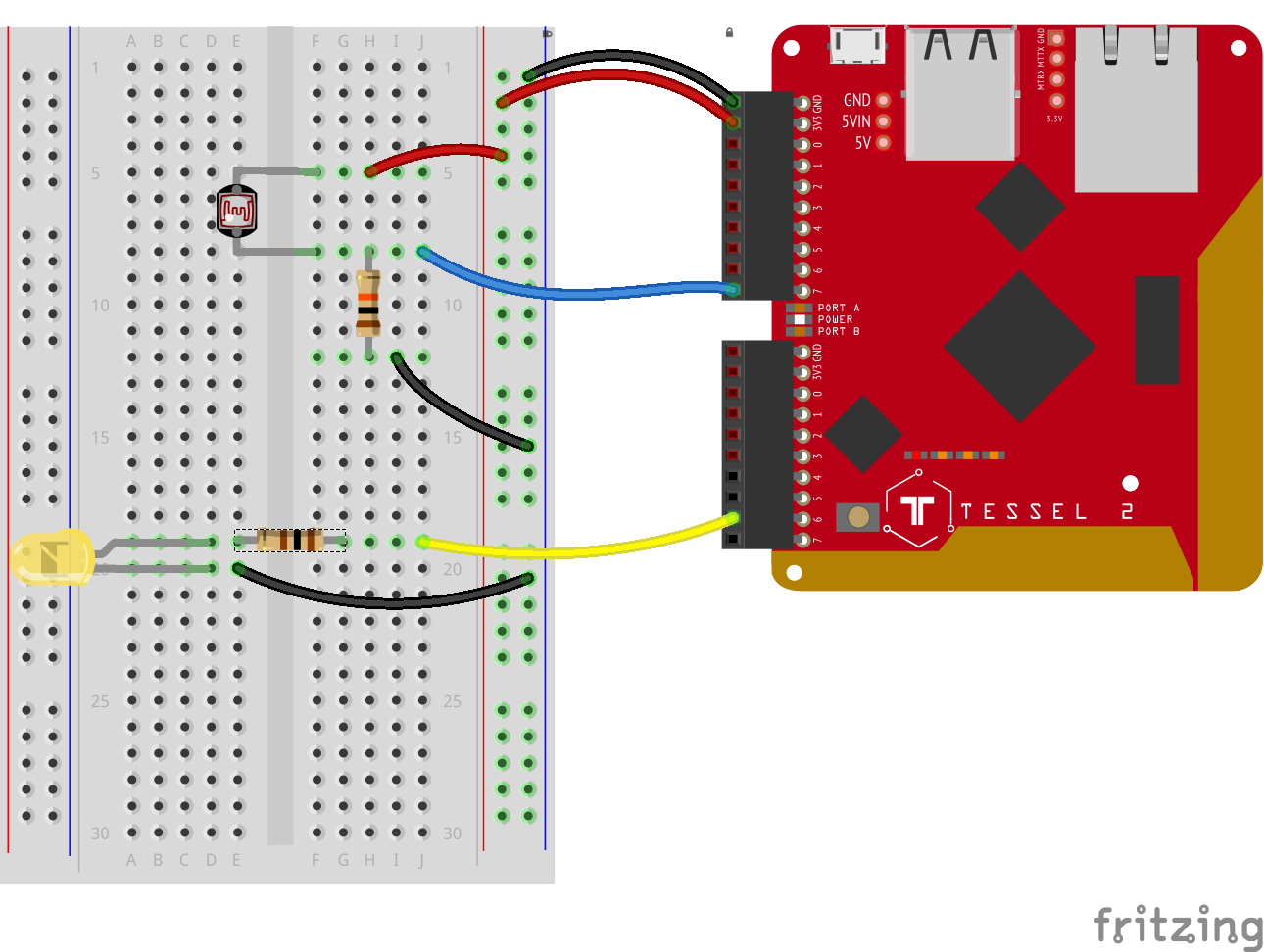
- Plug the photoresistor into the breadboard. It works fine in either orientation (it is not polarized). Connect a 10kΩ resistor between one leg of the photoresistor and ground. On the other side of the resistor, but in the same row, connect the photoresistor to Tessel 2's Port A, Pin 7 with a jumper wire.
- Connect the photoresistor to the supply voltage column on the power rail using a jumper wire. Connect the other end of the resistor to the ground column on the power rail with a jumper wire.
- Plug in the LED. Make sure not to plug it in backward! The anode (longer leg) should be connected with a jumper wire to Port B, Pin 6 through a 100Ω resistor. Connect the LED's cathode to the ground column on the power rail with a jumper wire.
- Use jumper wires to connect the Tessel's 3.3V and GND pins to the power rail of the breadboard.
Observing Light Intensity With Johnny-Five
Before we get into bar charts, let's take a look at the most basic observation example. Open your favorite code editor, create a file called light.js and save it in the j5ik/ directory. Type—or copy and paste—the following JavaScript code into your light.js file:
language:javascript
var five = require("johnny-five");
var Tessel = require("tessel-io");
var board = new five.Board({
  io: new Tessel()
});

board.on("ready", () => {
  var light = new five.Light("a7");

  light.on("change", () => console.log(light.level));
});
To Deploy Code Over WiFi:
- Connect your Tessel to the same Wifi network as your computer t2 wifi -n[SSID] -p[PASSWORD]`
- Make sure that your Tessel is provisioned and shows up in your list of Tessels using t2 list. See the Hardware Installation and Setup for how to provision your Tessel if it doesn't show up in your list.
- Deploy your code using the
--lantag. Example: t2 run mycode.js --lan
Type—or copy and paste—the following into your terminal:
t2 run light.js
Like the first program in Experiment 3, this isn't very interesting, but it does get us started! You'll see values between 0.00 and 1.00 scroll by in your terminal. Cover the photoresistor with your hand to see the values decrease.
Exploring the Code
Once the board has emitted the ready event, hardware inputs are ready for interaction. The Johnny-Five Light class is made for the job:
language:javascript
var light = new five.Light("a7");
Then a handler function is registered for change events. When the sensor's value changes, this function gets called.
language:javascript
light.on("change", () => console.log(light.level));
The handler function doesn't do much yet; it just logs out the current value of the level attribute. level is the current value read from the analog input pin, as a percentage (e.g., 0.38 is 38% of a possible 100%).
Graphing Light Intensity With Johnny-Five and Barcli
For this experiment, you will be "bar chart graphing" light intensity values in your terminal using the Barcli module:

barcli [bahrk-lee]
Barcli is a simple tool for displaying real-time data in the console. Multiple instances of Barcli can be stacked to show multiple axes, sensors or other data sources in an easy-to-read horizontal bar graph.
In your terminal, type—or copy and paste—the following command:
npm install barcli
Next, open your favorite code editor, create a file called light-bar-chart.js and save it in the j5ik/ directory. Type—or copy and paste—the following JavaScript code into your light-bar-chart.js file:
language:javascript
var Barcli = require("barcli");
var five = require("johnny-five");
var Tessel = require("tessel-io");
var board = new five.Board({
  io: new Tessel(),
  // Experiment 3 explains these options
  repl: false,
  debug: false,
});

board.on("ready", function() {
  var graph = new Barcli({
    color: "white",
    label: "Light Level",
    range: [0, 1],
  });
  var light = new five.Light("a7");

  light.on("change", () => {
    graph.update(light.level);
  });
});
To Deploy Code Over WiFi:
- Connect your Tessel to the same Wifi network as your computer t2 wifi -n[SSID] -p[PASSWORD]`
- Make sure that your Tessel is provisioned and shows up in your list of Tessels using t2 list. See the Hardware Installation and Setup for how to provision your Tessel if it doesn't show up in your list.
- Deploy your code using the
--lantag. Example: t2 run mycode.js --lan
Type—or copy and paste—the following into your terminal:
t2 run light-bar-chart.js
Once the program starts up, the terminal should display something like this:
(This was produced by shining a small LED flashlight back and forth over the sensor. Results will vary by source and ambient light.)
Exploring the Code
To create a graph, first initialize a new instance of Barcli with a range of [0, 1] to match the range of light level values (see Experiment 3 for more background on barcli and scaling). To make the bar visually suggestive of "light level", set the color to "white":
language:javascript
var graph = new Barcli({
  color: "white",
  label: "Light Level",
  range: [0, 1],
});
Now, update the change event-handler function:
language:javascript
var light = new five.Light("a7");

light.on("change", () => {
  graph.update(light.level);
});
Last, call graph.update(light.level) to update the chart with the most recent light level readings.
Variation: Building a Light-Sensing Nightlight
How about using a photoresistor to help determine when a nightlight should be turned on? The general idea is: when the room is dim, turn the light on. When the room is bright, turn the light off.
Open your favorite code editor, create a file called nightlight.js and save it in the j5ik/ directory. Type—or copy and paste—the following JavaScript code into your nightlight.js file:
language:javascript
var five = require("johnny-five");
var Tessel = require("tessel-io");
var board = new five.Board({
  io: new Tessel()
});

board.on("ready", () => {
  var light = new five.Light({
    pin: "a7"
  });
  var nightlight = new five.Led("b6");
  light.on("change", () => {
    if (light.level < 0.5) {
      nightlight.on();
    } else {
      nightlight.off();
    }
  });
});
Type—or copy and paste—the following into your terminal:
t2 run nightlight.js
Cover and uncover the photoresistor with your hand to change its light readings.
light.level may never get lower than 0.5. If this happens for you change the if(light.level < 0.5) statement in your code to have a higher threshold...maybe something like 0.7? What You Should See
Covering the photoresistor with your hand to block light should cause the nightlight to turn on, while shining a pen light onto the photoresistor or otherwise exposing it to bright light should make the nightlight turn off.
Exploring the Code
After the board is ready, and the light (photoresistor Light) and nightlight (Led) instances have been created, the next trick is to attach an event handler to the photoresistor's change event:
language: javascript
light.on("change", () => {
  if (light.level < 0.5) {
    nightlight.on();
  } else {
    nightlight.off();
  }
});
light.level returns a the photo-sensor's 10-bit value (0 - 1023) rescaled to a range between 0 and 1. If the room is dim(ish)—a light.level of less than 0.5—turn the nightlight on. Otherwise, turn it off.
Making the Nightlight Better
Ahem. That first attempt is a little inelegant, for a couple of reasons:
- The values read from the
lightobject are not going to span the full possible 10-bit range of 0--1023. Using the 10kΩ resistor in the voltage divider will result in output voltages that cover much of the 0--3.3V range, but not all. Also, you might not have the ability to expose the photoresistor to a fully dark condition or a fully bright one, depending on where you are doing your work. - Light levels near the threshold (
light.levelof0.5, which is the same aslight.valueof511on a 0--1023 scale) can cause obnoxious blinking on and off of the LED.
We can do a little better. Try typing or pasting the following code into your nightlight.js file:
language:javascript
var five = require("johnny-five");
var Tessel = require("tessel-io");
var board = new five.Board({
  io: new Tessel()
});

board.on("ready", () => {
  var light = new five.Light("a7");
  var nightlight = new five.Led("b6");
  var dimmest = 1023;
  var brightest = 0;

  light.on("change", () => {
    var relativeValue;
    if (light.value < dimmest) {
      dimmest = light.value;
    }
    if (light.value > brightest) {
      brightest = light.value;
    }
    relativeValue = five.Fn.scale(light.value, dimmest, brightest, 0, 511);
    if (relativeValue <= 255) {
      nightlight.brightness(255 - relativeValue);
    } else {
      nightlight.off();
    }
  });
});
Now, once again type—or copy and paste—the following into your terminal:
t2 run nightlight.js
Once again cover and uncover the photoresistor or shine a penlight onto it.
What You Should See
At first you may see the nightlight blinking a little, but as the script calibrates and gathers readings, the range and scaling makes the nightlight behave more smoothly. As the photoresistor is covered with your hand, the nightlight should fade to brighter. As you remove your hand, it should fade back down to off.
Exploring the Code
Outside of the event-handling function, we create a couple of variables to keep track of the dimmest and brightest values the light object encounters, over time:
language:javascript
var dimmest = 1023;
var brightest = 0;
Now let's look at the first part of the updated change event-handling function:
language:javascript
light.on("change", () => {
  var relativeValue; // We'll get to this in a moment
  if (light.value < dimmest) {
    dimmest = light.value;
  }
  if (light.value > brightest) {
    brightest = light.value;
  }
  // ...
});
This keeps track of the lowest and highest readings from the photoresistor over time. If the value of the photoresistor is dimmer (lower) than the current value of dimmest, update dimmest to the new value. Likewise, if the value of the photoresistor is brighter (higher) than the current value of brightest, update brightest to the most recent value. This happens on each iteration, assuring that dimmest and brightest are always up to date with the low and high bounds of all readings.
The current light.value falls somewhere in between dimmest and brightest (inclusive). [dimmest, brightest] is, in fact, the scale of our readings so far. We need to take the information gathered so far and figure out whether the nightlight should be on at all, and, if so, how bright it should be.
Here are some rules and background:
- The nightlight shouldn't be on at all if the current reading falls in the top (brighter) half of the range of all readings ever seen.
- The
brightnessmethod onLedobject instances takes an 8-bit number (0--255), where 0 is off and 255 is full brightness. - The nightlight should be brightest (255) when the photoresistor is at its lowest reading (
dimmest). - The nightlight should dim as photoresistor readings increase from
dimmest, dimming to0(off) at the midpoint of the[dimmest, brightest]range.
five.Fn.scale(value, oldLow, oldHigh, newLow, newHigh) is a method that remaps a value from its old range to a new range. The following line rescales the current value, based on its current range ([dimmest, brightest]) to a range representing 9-bit numbers ([0, 511]).
language:javascript
relativeValue = five.Fn.scale(light.value, dimmest, brightest, 0, 511);
Per rule 1 above—only values in the lower half of the scale should cause the LED nightlight to be on. So:
language:javascript
if (relativeValue <= 255) {
  // Set the nightlight to some brightness between 0 and 255
  // Note the nice 8-bit number we have to work with now
} else {
  nightlight.off();
}
relativeValue values between 0 and 255 should cause the nightlight to be on. However, the higher the relativeValue is in that range, the dimmer the LED should be. We can adjust for that by subtracting relativeValue from 255 to get the appropriate brightness for the nightlight:
language:javascript
if (relativeValue <= 255) {
  nightlight.brightness(255 - relativeValue);
} else {
  nightlight.off();
}
Building Further
- Try adding a potentiometer to the circuit, and use it to control the ambient-light threshold at which the nightlight turns on.
- Trying using
tessel-av, an external sound adapter and a set of speakers to make audible notifications for various light levels. - Also with
tessel-av, use light level to trigger the start and stop of video surveillance. Look at using IFTTT Maker Channel to alert you when someone turns on the lights in your room.
Reading Further
- JavaScript — JavaScript is the programming language that you'll be using.
- Node.js — Node.js is the JavaScript runtime where your programs will be executed.
- Johnny-Five — Johnny-Five is a framework written in JavaScript for programming hardware interaction on devices that run Node.js.