Experiment Guide for the SparkFun Tinker Kit
This Tutorial is Retired!
This tutorial covers concepts or technologies that are no longer current. It's still here for you to read and enjoy, but may not be as useful as our newest tutorials.
View the updated tutorial: Activity Guide for SparkFun Tinker Kit
 D___Run___
 Introduction to the SparkFun Tinker Kit
This SparkFun Tinker Kit Experiment Guide is your map for navigating the waters of beginning embedded electronics, robotics and citizen science using the SparkFun RedBoard while sticking to a strict budget. This guide contains all the information you will need to explore the 11 circuits of the SparkFun Tinker Kit. At the center of this guide is one core philosophy -- that anyone can (and should) play around with cutting-edge electronics in a fun and playful way while not breaking the bank.
When you're done with this guide, you'll have the know-how to start creating your own projects and experiments. From building robots and game controllers to data logging, the world will be your oyster. Now enough talking -- let's start tinkering!
Included Materials
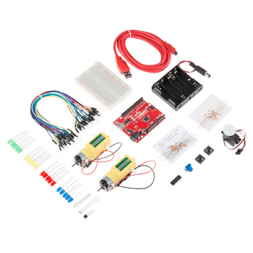
Here are all of the parts in the SparkFun Tinker Kit:
- SparkFun RedBoard -- Our tried and true version of the Arduino UNO.
- Breadboard -- Excellent for making circuits and connections off the Arduino.
- SparkFun Mini Screwdriver -- To help you screw your RedBoard onto the holder.
- Hobby Gearmotor Set -- A set of hobby level motors with gearboxes set to 120 RPM.
- Small Servo -- Here is a simple, low-cost, high-quality servo for all your mechatronic needs.
- TMP36 Temp Sensor -- A sensor for detecting temperature changes.
- ** USB A to B Cable** -- This 6-foot cable provides you with a USB-A connector at the host end and standard B connector at the device end.
- Male-to-Male Jumper Wires -- These are high-quality wires that allow you to connect the female headers on the Arduino to the components and breadboard.
- Photocell -- A sensor to detect ambient light. Perfect for detecting when a drawer is opened or when nighttime approaches.
- Tri-Color LED -- Because everyone loves a blinky.
- Red, Blue, Yellow and Green LEDs -- Light-Emitting Diodes make great general indicators.
- Red, Blue, Yellow and Green Tactile Buttons -- Go crazy with different colored buttons.
- 10K Trimpot -- Also known as a variable resistor, this is a device commonly used to control volume and contrast, and makes a great general user control input.
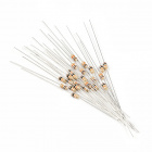
- 330 Ohm Resistors -- Great current-limiting resistors for LEDs, and strong pull-up resistors.
- 10K Ohm Resistors -- These make excellent pull-ups, pull-downs and current limiters.
- SN754410 H-Bridge IC -- This nifty little Integrated Circuit (IC) is perfect for controlling the speed and direction of up to two separate motors.
- 4xAA Battery Holder -- Used to power the RedBoard without being connected to your computer. Sorry! Batteries not included.
Experiment List
The following is a list of the experiments you will complete using this Tinker Kit Experiment Guide. Alternatively, you can navigate around using the buttons on the right.
- Experiment 1: Blinking an LED
- Experiment 2: Reading a Potentiometer
- Experiment 3: Driving an RGB LED
- Experiment 4: Driving Multiple LEDs
- Experiment 5: Reading a Button Press
- Experiment 6: Reading a Photoresistor
- Experiment 7: Reading a Temperature Sensor
- Experiment 8: Using a Servo Motor
- Experiment 9: Driving a Motor with an H-Bridge
- Experiment 10: Controlling a Motor with Inputs
- Experiment 11: Reading Serial Data
Suggested Reading
Before continuing with this guide, we recommend you be somewhat familiar with the concepts in the following tutorials:
- Voltage, Current, Resistance, and Ohm's Law - The most basic concepts in electronics and electrical engineering. Get very familiar with these concepts as they will be used throughout your electronics adventure.
- What is a Circuit? - In this guide, we will be building a variety of circuits. Understanding what that means is vital to understanding the Inventor's Kit.
- How to Use a Breadboard -- First time working with a breadboard? Please check out this tutorial! It will help you understand why the breadboard is great for prototyping and how to use one.
Open Source!
At SparkFun, our engineers and educators have been improving this kit and coming up with new experiments for a long time. We would like to give attribution to Oomlout, since we originally started working off the Arduino Kit material many years ago. Both the Oomlout and SparkFun versions are licensed under the Creative Commons Attribution Share-Alike 3.0 Unported License.
To view a copy of this license visit this link, or write: Creative Commons, 171 Second Street, Suite 300, San Francisco, CA 94105, USA.
What is the RedBoard?

At SparkFun we use many Arduinos, and we’re always looking for the simplest, most stable one. Each board is a bit different, and no one board has everything we want, so we decided to make our own version that combines all our favorite features. The SparkFun RedBoard combines the simplicity of the UNO’s Optiboot bootloader (which is used in the Pro series), the stability of the FTDI (which we all missed after the Duemilanove was discontinued) and the R3 shield compatibility of the latest Arduino UNO R3.
The RedBoard can be programmed over a USB Mini-B cable using the Arduino IDE: Just plug in the board, select “Arduino UNO” from the board menu, and you’re ready to upload code. RedBoard has all of the hardware peripherals you know and love: 14 Digital I/O pins with 6 PWM pins, 6 Analog Inputs, UART, SPI and external interrupts. We’ve also broken out the SDA, SCL and IOREF pins that showed up on the UNO R3, so the RedBoard will be compatible with future shields. This version adds an SMD ISP header for use with shields.
You can power the RedBoard over USB or through the barrel jack. The on-board power regulator can handle anything from 7 to 15VDC. Check out the related items below for a compatible wall-wart power supply.
Introduction to the Arduino IDE
Before you plug the RedBoard into your computer, you'll need to install Arduino.
Installing Arduino
To begin, head over to Arduino's download page and grab the most recent, stable release of Arduino. Make sure you grab the version that matches your operating system.
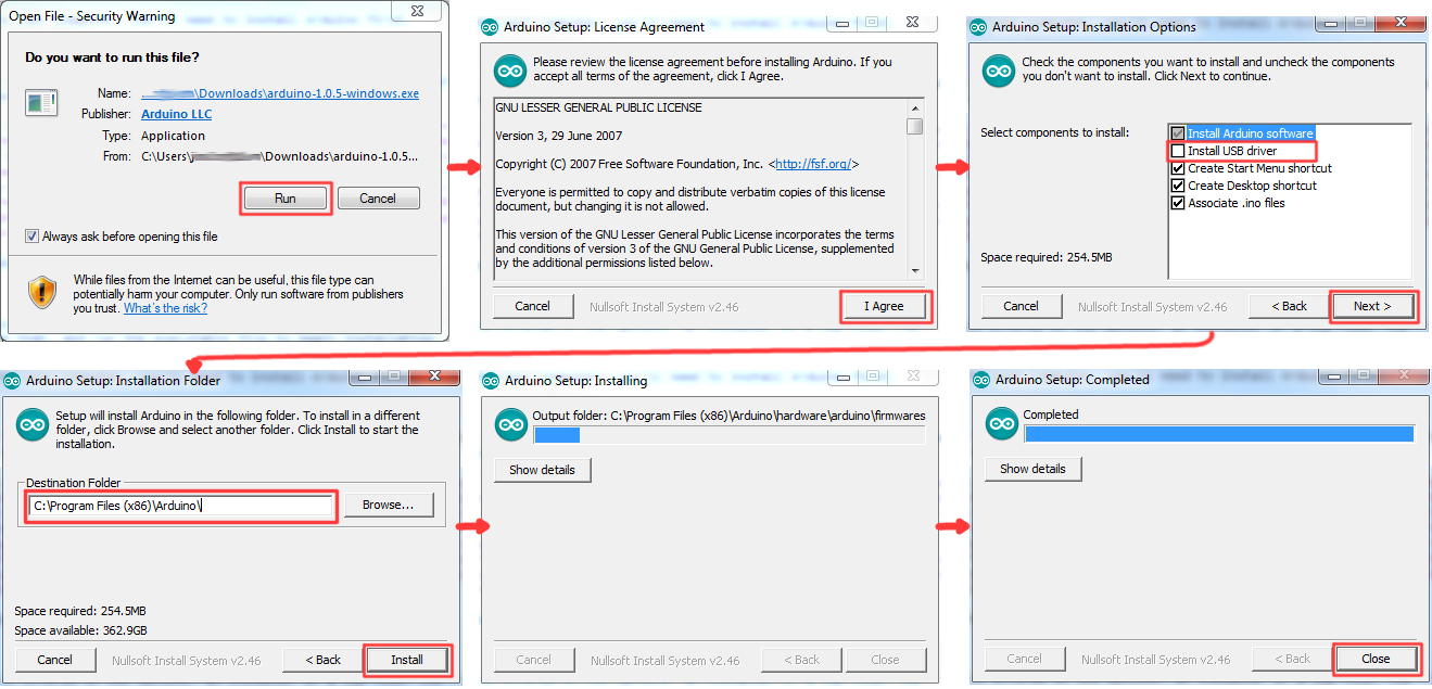
The installation procedure is fairly straightforward, but it varies by OS. Here are some tips to help you along. We've also written a separate Installing Arduino tutorial if you get really stuck.
Windows Install Tips
The Windows version of Arduino is offered in two options: an installer or a zip file. The installer is the easier of the two options; just download that, and run the executable file to begin installation. If you're prompted to install a driver during installation, select "Don't Install" (the RedBoard doesn't use the same drivers). Don't forget which directory it installs to (defaults to "Program Files/Arduino").
If, instead, you choose to download the zip file version of Arduino, you'll need to extract the files yourself. Don't forget which folder you extract the files into! We'll need to reference that directory when we install drivers.
Mac Install Tips
The Mac download of Arduino is only offered in a zip file version. After the download is finished, simply double-click the .zip file to unzip it.

Following that, you'll need to copy the Arduino application into your applications folder to complete installation.
Linux Install Tips
As Linux users are no doubt aware, there are many flavors of Linux out there, each with unique installation routines. Check out the Linux section of the Installing Arduino tutorial for some helpful links for an assortment of Linux distributions.
For Ubuntu and Debian users, installing Arduino should be as easy as running a little "apt-get" magic, with a command like:
sudo apt-get update && sudo apt-get install arduino arduino-core
And other Linux distros aren't too dissimilar from that.
With Arduino downloaded and installed, the next step is to plug the RedBoard in and install some drivers! Pretty soon you'll be blinking LEDs, reading buttons, and doing some physical computing!
Installing FTDI Drivers
Once you have downloaded and installed Arduino, it's time to connect the RedBoard to your computer! Before you can use the board, though, you'll need to install drivers.
Windows Driver Installation
After initially plugging your RedBoard in, your computer will try to search for a compatible driver. It may actually succeed! The FTDI drivers are pretty common, so Windows Update may know a little something about them. If the drivers do automatically install, you should see a little bubble notification saying so:
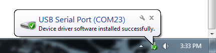
If your computer failed to find drivers, we'll have to install them manually. Check out our Windows FTDI Driver install guide for driver installation instructions.
Mac Driver Installation
If you're lucky, the FTDI drivers should automatically install on Mac OS X; otherwise you'll have to manually install the drivers. Check out the Mac FTDI Driver install guide for help installing the drivers.
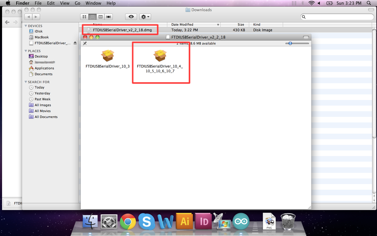
In short, the process involves heading over to the FTDI driver website, and downloading the most up-to-date VCP drivers. Then you'll simply run the "FTDIUSBSerialDriver_v2_2_18.dmg" file you downloaded, and follow the installation prompts.
Linux Driver Installation
Linux is actually pretty good about automatically installing the drivers. If you have any trouble, check out our Linux FTDI Driver install guide.
Now it's time to breathe easy! You'll only have to run through this driver installation process once, the first time you connect the board to your computer. Now it's time to upload a sketch!
Experiment 1: Blink an LED
Introduction
LEDs are small, powerful lights that are used in many different applications. To start off, we will work on blinking an LED, the "Hello, World!" of microcontrollers. That's right -- it's as simple as turning a light on and off. It might not seem like much, but establishing this important baseline will give you a solid foundation as we work toward more complex experiments.
Parts Needed
You will need the following parts:
- 1x Breadboard
- 1x SparkFun RedBoard
- 1x LED
- 1x 330Ω Resistor
- 3x Jumper Wires
Didn't Get the Tinker Kit?
If you are conducting this experiment and didn't get the Tinker Kit, we suggest using these parts:


Suggested Reading
Before continuing with this experiment, we recommend you be familiar with the concepts in the following tutorial:
- Light-Emitting Diodes -- Learn more about LEDs!
Introducing the LED
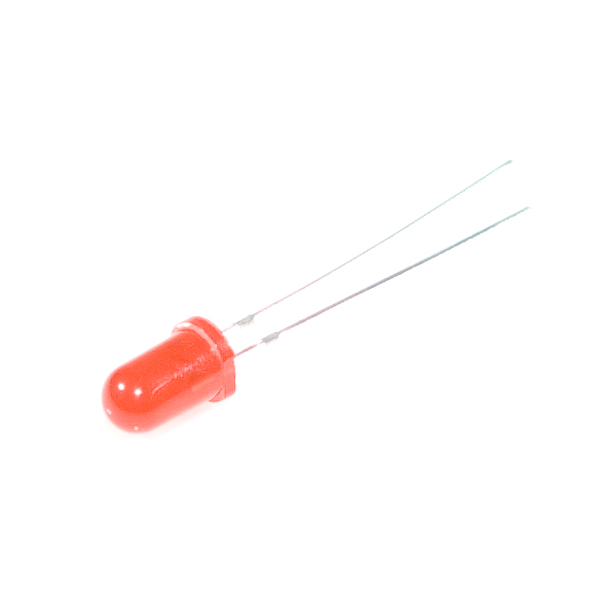
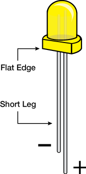
A Light-Emitting Diode (LED) will only let current through it in one direction. Think of an LED as a one-way street. When current flows through the LED, it lights up! When you are looking at the LED, you will notice that its legs are different lengths. The long leg, the "anode," is where current enters the LED. This pin should always be connected to the current source. The shorter leg, the "cathode," is the current’s exit. The short leg should always be connected to a pathway to ground.
LEDs are finicky when it comes to how much current you apply to them. Too much current can lead to a burnt-out LED. To restrict the amount of current that passes through the LED, we use a resistor in line with the power source and the LED's long leg; this is called a current-limiting resistor. With the RedBoard, you should use a 330 Ohm resistor. We have included a baggy of them in the kit just for this reason!
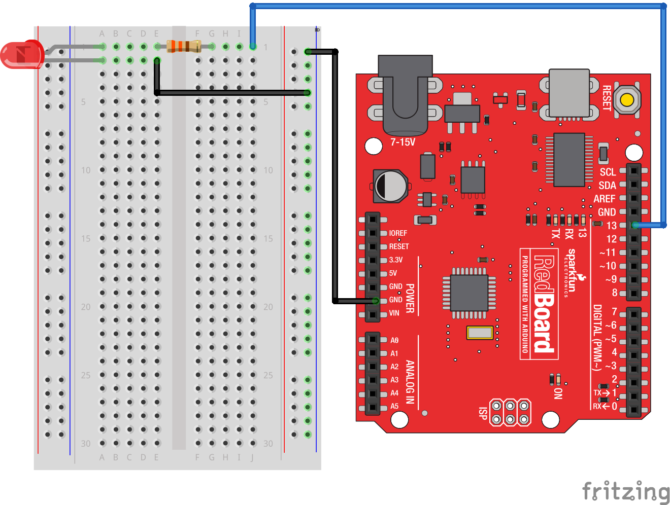
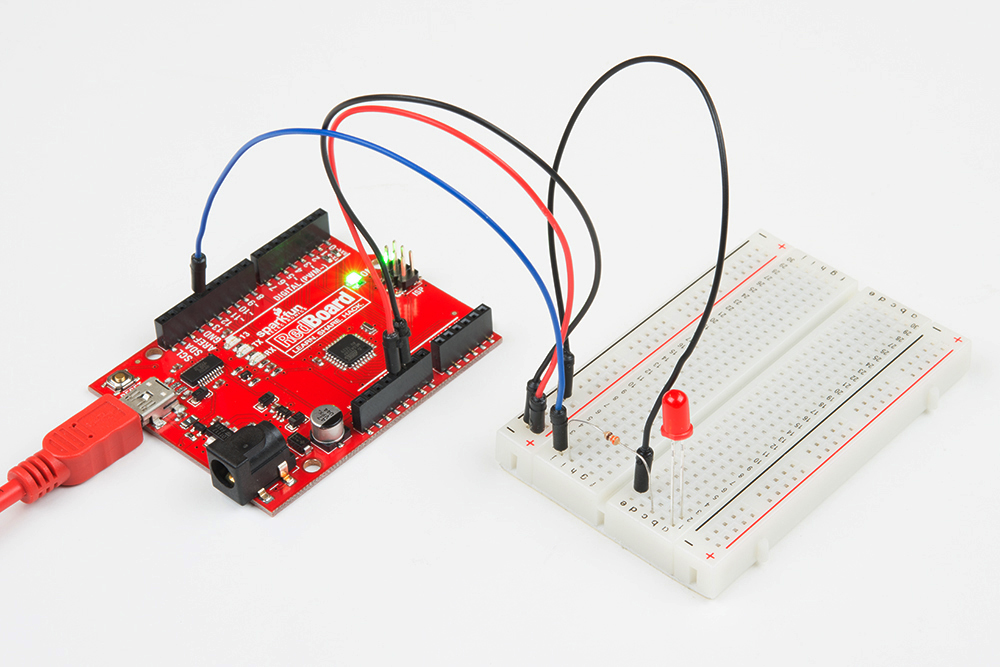
Hardware Hookup
Ready to start hooking everything up? Check out the wiring diagram and hookup table below to see how everything is connected.
| Polarized Components | Pay special attention to the component’s markings indicating how to place it on the breadboard. Polarized components can only be connected to a circuit in one direction. |
**Please note: Pay close attention to the LED. The negative side of the LED is the short leg, marked with a flat edge. **
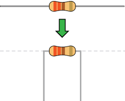
Components like resistors need to have their legs bent into 90° angles in order to correctly fit the breadboard sockets. You can also cut the legs shorter to make them easier to work with on the breadboard.
Wiring Diagram for the Experiment
Open Your First Sketch
Open the Arduino IDE software on your computer. Coding in the Arduino language will control your circuit.
You can type out or copy and paste the following code into the Arduino IDE. Hit upload, and see what happens!
language:cpp
/*
SparkFun Tinker Kit
Example sketch 01

BLINKING AN LED

Turn an LED on for one second, off for one second,
and repeat forever.

This sketch was written by SparkFun Electronics,
with lots of help from the Arduino community.
This code is completely free for any use.
Visit http://learn.sparkfun.com/products/2 for SIK information.
Visit http://www.arduino.cc to learn about Arduino.
*/


//The setup function runs once upon your Arduino being powered or once upload is          //complete.

void setup()
{
  //set pin 13 to OUTPUT
  pinMode(13, OUTPUT);
}

//The loop function runs from the top down and repeats itself until you upload new        //code or power down your Arduino
void loop()
{
  //Turn pin 13 HIGH (ON).
  digitalWrite(13, HIGH);

  //wait 1000 milliseconds (1 second)
  delay(1000);

  //Turn pin 13, LOW (OFF)
  digitalWrite(13, LOW);

  //wait 1000 milliseconds
  delay(1000);
}
Code to Note
pinMode(13, OUTPUT);
Before you can use one of the RedBoards' pins, you need to tell the board whether it is an INPUT or OUTPUT. We use a built-in "function" called pinMode() to do this.
digitalWrite(13, HIGH);
When you're using a pin as an OUTPUT, you can command it to be HIGH (output 5 volts), or LOW (output 0 volts).
What You Should See
You should see your LED blink on and off. If it doesn't, make sure you have assembled the circuit correctly and verified and uploaded the code to your board, or see the Troubleshooting section.
Troubleshooting
Program Not Uploading
This happens sometimes; the most likely cause is a confused serial port. You can change this in Tools > Serial Port >
Still No Success
A broken circuit is no fun. Send us an email, and we will get back to you as soon as we can: techsupport@sparkfun.com
Experiment 2: Reading a Potentiometer
Introduction
In this circuit you will work with a potentiometer. You will learn how to use a potentiometer to control the timing of a blinking LED by reading a sensor and storing it as a variable, then using it as your delay timing.
Parts Needed
You will need the following parts:
- 1x Breadboard
- 1x SparkFun RedBoard
- 1x LED
- 1x 330Ω Resistor
- 7x Jumper Wires
- 1x Potentiometer
Didn't Get the Tinker Kit?
If you are conducting this experiment and didn't get the Tinker Kit, we suggest using these parts:

Suggested Reading
Before continuing with this experiment, we recommend you be familiar with the concepts in the following tutorial:
Introducing the Potentiometer
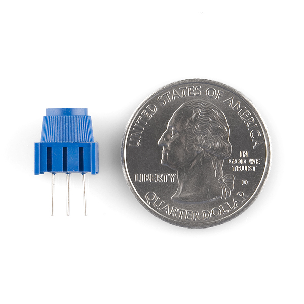
A potentiometer is a resistance-based analog sensor that changes its internal resistance based on the rotation of its knob. The potentiometer has an internal voltage divider enabling you to read the change in voltage on the center pin with a microcontroller (the RedBoard). To hook up the potentiometer, attach the two outside pins to a supply voltage (5V in this circuit) and ground. It doesn’t matter which is connected where, as long as one is connected to power, and the other to ground. The center pin is then connected to an analog input pin so the RedBoard can measure the change in voltage. When you twist the knob, the sensor reading will change!
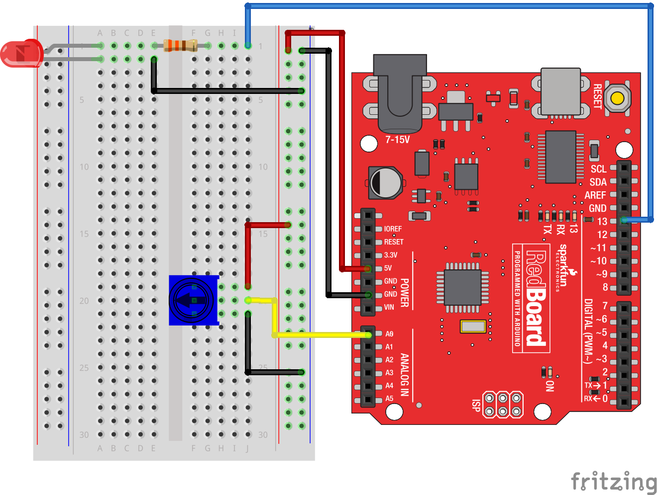
Hardware Hookup
Ready to start hooking everything up? Check out the wiring diagram and hookup table below to see how everything is connected.
| Polarized Components | Pay special attention to the component’s markings indicating how to place it on the breadboard. Polarized components can only be connected to a circuit in one direction. |
Wiring Diagram for the Experiment
Open the Sketch
Open the Arduino IDE software on your computer. Coding in the Arduino language will control your circuit.
You can type out or copy and paste the following code into the Arduino IDE. Hit upload, and see what happens!
language:cpp
/* SparkFun Tinker Kit
Example sketch 02

POTENTIOMETER

  Measure the position of a potentiometer and use it to
  control the blink rate of an LED. Turn the knob to make
  it blink faster or slower!

This sketch was written by SparkFun Electronics,
with lots of help from the Arduino community.
This code is completely free for any use.
Visit http://learn.sparkfun.com/products/2 for SIK information.
Visit http://www.arduino.cc to learn about Arduino.
*/


//Create global variables (variables that can be used anywhere in our sketch)

// Here we're creating a variable called "sensorPin" of type "int"
// and initializing it to have the value "0," which is the analog input pin the pot is     //conected to.
int sensorPin = 0;

// Variable for storing the pin number that the LED is connected to
int ledPin = 13;

// this function runs once when the sketch starts up
void setup()
{
  //set ledPin (13) as an OUTPUT
  pinMode(ledPin, OUTPUT);
}

// this function runs repeatedly after setup() finishes
void loop()
{

  //create a local variable (variable that can only be used inside of loop() to store       //a sensor value called sensorValue
  int sensorValue;

  //use the analogRead() function to read sensorPin and store the value in sensorValue
  sensorValue = analogRead(sensorPin);

  // Turn the LED on
  digitalWrite(ledPin, HIGH);


  delay(sensorValue);

  // Turn the LED off
  digitalWrite(ledPin, LOW);

 //delay for the value of sensorValue
  delay(sensorValue);

  //loop back to the top
}
Code to Note
int sensorValue;
A “variable” is a placeholder for values that may change in your code. You must introduce, or "declare," variables before you use them; here you are declaring a variable called sensorValue, of type "int" (integer). Don't forget that variable names are case sensitive!
sensorValue = analogRead(sensorPin);
Use the analogRead() function to read the value on an analog pin. analogRead() takes one parameter, the analog pin you want to use ("sensorPin"), and returns a number ("sensorValue") between 0 (0 volts) and 1023 (3.3 volts).
delay(sensorValue);
Microcontrollers are very fast, capable of running thousands of lines of code each second. To slow it down so that we can see what it's doing, we'll often insert delays into the code. delay() counts in milliseconds; there are 1,000 ms in one second.
What You Should See
You should see the LED blink faster or slower in accordance with your potentiometer. If it isn't working, make sure you have assembled the circuit correctly and verified and uploaded the code to your board, or see the Troubleshooting section.

Troubleshooting
Sporadically Working
This is most likely due to a slightly dodgy connection with the potentiometer's pins. This can usually be conquered by holding the potentiometer down or moving the potentiometer circuit somewhere else on your breadboard.
Not Working
Make sure you haven’t accidentally connected the wiper (center pin), the resistive element in the potentiometer, to digital pin 0 rather than analog pin 0 (the row of pins beneath the power pins).
LED Not Lighting Up
LEDs will only work in one direction. Double check your connections.
Experiment 3: Driving an RGB LED
Introduction
You know what’s even more fun than a blinking LED? Changing colors with one LED. In this circuit, you’ll learn how to use an RGB LED to create unique color combinations. Depending on how bright each diode is, nearly any color is possible!
Parts Needed
You will need the following parts:
- 1x Breadboard
- 1x SparkFun RedBoard
- 1x Common Cathode RGB LED
- 3x 330Ω Resistors
- 6x Jumper Wires
Didn't Get the Tinker Kit?
If you are conducting this experiment and didn't get the Tinker Kit, we suggest using these parts:
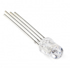
Introducing the Red Green Blue (RGB) LED
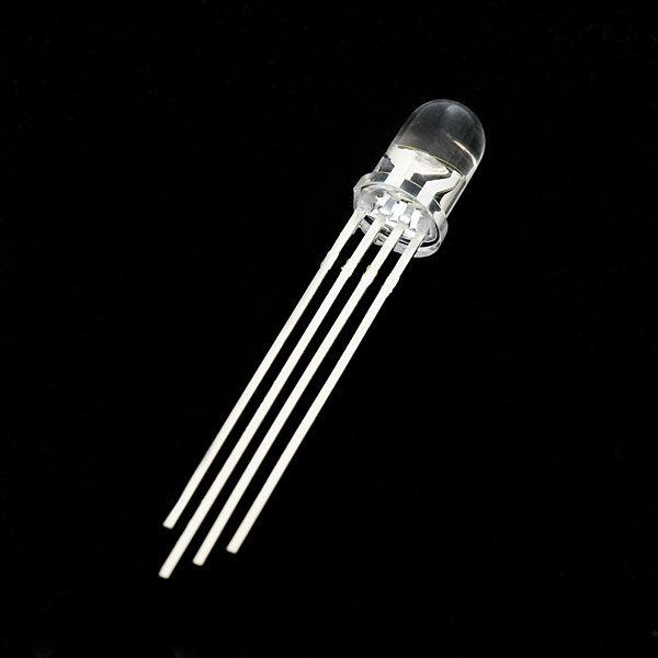
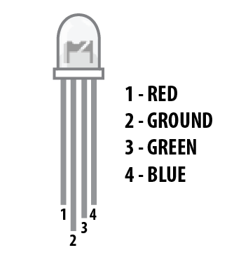
The Red Green Blue (RGB) LED is 3 LEDs in one. The RGB has four pins with each of the three shorter pins controlling an individual color: red, green or blue. The longer pin of the RGB is the common ground pin. You can create a custom colored LED by turning different colors on and off to combine them. For example, if you turn on the red pin and green pin, the RGB will light up as yellow.
But which pin is which color? Pick up the RGB so that the longest pin (common ground) is aligned to the left as shown in the graphic below. The pins are Red, Ground, Green and Blue -- starting from the far left.
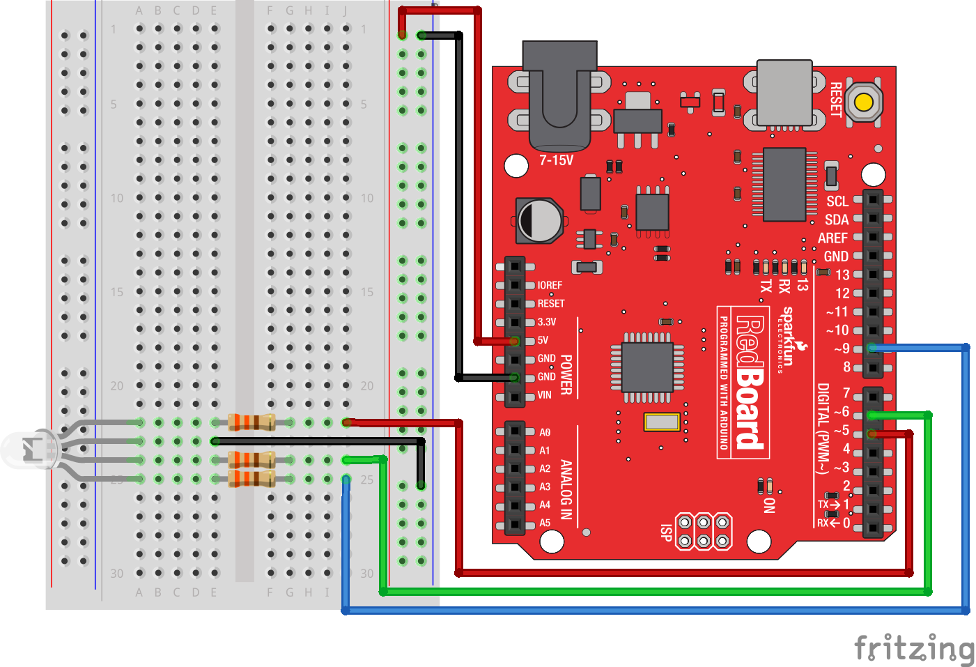
Hardware Hookup
Ready to start hooking everything up? Check out the wiring diagram and hookup table below to see how everything is connected.
| Polarized Components | Pay special attention to the component’s markings indicating how to place it on the breadboard. Polarized components can only be connected to a circuit in one direction. Polarized components are highlighted with a yellow warning triangle in the table below. |
Wiring Diagram for the Experiment
Open the Sketch
Open the Arduino IDE software on your computer. Coding in the Arduino language will control your circuit.
You can type out or copy and paste the following code into the Arduino IDE. Hit upload, and see what happens!
language:cpp
/*
SparkFun Tinker Kit
Example sketch 03

RGB LED

Make an RGB LED display a rainbow of colors!


This sketch was written by SparkFun Electronics,
with lots of help from the Arduino community.
Visit http://learn.sparkfun.com/products/2 for SIK information.
Visit http://www.arduino.cc to learn about Arduino.
*/

//create variables for pin numbers. We are making them constants here, because they       //never change.
const int RED_PIN = 5;
const int GREEN_PIN = 6;
const int BLUE_PIN = 9;

// How fast we plan to cycle through colors in milliseconds
int DISPLAY_TIME = 10;


void setup()
{
//set the three pin variables as outputs
pinMode(RED_PIN, OUTPUT);
pinMode(GREEN_PIN, OUTPUT);
pinMode(BLUE_PIN, OUTPUT);
}


void loop()
{
// We've written a custom function called mainColors() that steps
// through all eight of these colors. We're only "calling" the
// function here (telling it to run). The actual function code
// is further down in the sketch.
mainColors();


}


// Here's the mainColors() custom function we've written.
void mainColors()
{
// Off (all LEDs off):
digitalWrite(RED_PIN, LOW);
digitalWrite(GREEN_PIN, LOW);
digitalWrite(BLUE_PIN, LOW);

//wait 1 second
delay(1000);

// Red (turn just the red LED on):
digitalWrite(RED_PIN, HIGH);
digitalWrite(GREEN_PIN, LOW);
digitalWrite(BLUE_PIN, LOW);

//wait 1 seconds
delay(1000);

// Green (turn just the green LED on):
digitalWrite(RED_PIN, LOW);
digitalWrite(GREEN_PIN, HIGH);
digitalWrite(BLUE_PIN, LOW);

//wait 1 second
delay(1000);

// Blue (turn just the blue LED on):
digitalWrite(RED_PIN, LOW);
digitalWrite(GREEN_PIN, LOW);
digitalWrite(BLUE_PIN, HIGH);

//wait 1 second
delay(1000);

// Yellow (turn red and green on):
digitalWrite(RED_PIN, HIGH);
digitalWrite(GREEN_PIN, HIGH);
digitalWrite(BLUE_PIN, LOW);

//wait 1 second
delay(1000);

// Cyan (turn green and blue on):
digitalWrite(RED_PIN, LOW);
digitalWrite(GREEN_PIN, HIGH);
digitalWrite(BLUE_PIN, HIGH);

//wait 1 second
delay(1000);

// Purple (turn red and blue on):
digitalWrite(RED_PIN, HIGH);
digitalWrite(GREEN_PIN, LOW);
digitalWrite(BLUE_PIN, HIGH);

//wait 1 second
delay(1000);

// White (turn all the LEDs on):
digitalWrite(RED_PIN, HIGH);
digitalWrite(GREEN_PIN, HIGH);
digitalWrite(BLUE_PIN, HIGH);

//wait 1 second
delay(1000);
}
Code to Note
language:cpp
for (x = 0; x < 768; x++)
{}
A for() loop is used to repeat an action a set number of times across a range, and repeatedly runs code within the brackets {}. Here the variable "x" starts at 0, ends at 767, and increases by one each time ("x++").
language:cpp
if (x <= 255)
{}
else
{}
"If/else" statements are used to make choices in your programs. The statement within the parentheses ( ) is evaluated; if it's true, the code within the first brackets { } will run. If it's not true, the code within the second brackets { } will run.
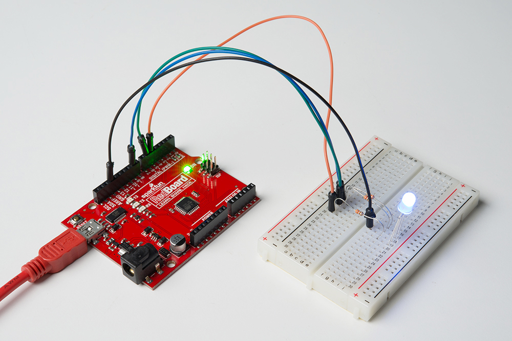
What You Should See
You should see your LED turn on, but this time in new, crazy colors! If it doesn't, make sure you have assembled the circuit correctly and verified and uploaded the code to your board, or see the Troubleshooting section.
Troubleshooting
LED Remains Dark or Shows Incorrect Color
With the four pins of the LED so close together, it’s sometimes easy to misplace one. Double check that each pin is where it should be.
Seeing Red
The red diode within the RGB LED may be a bit brighter than the other two. To make your colors more balanced, use a higher ohm resistor.
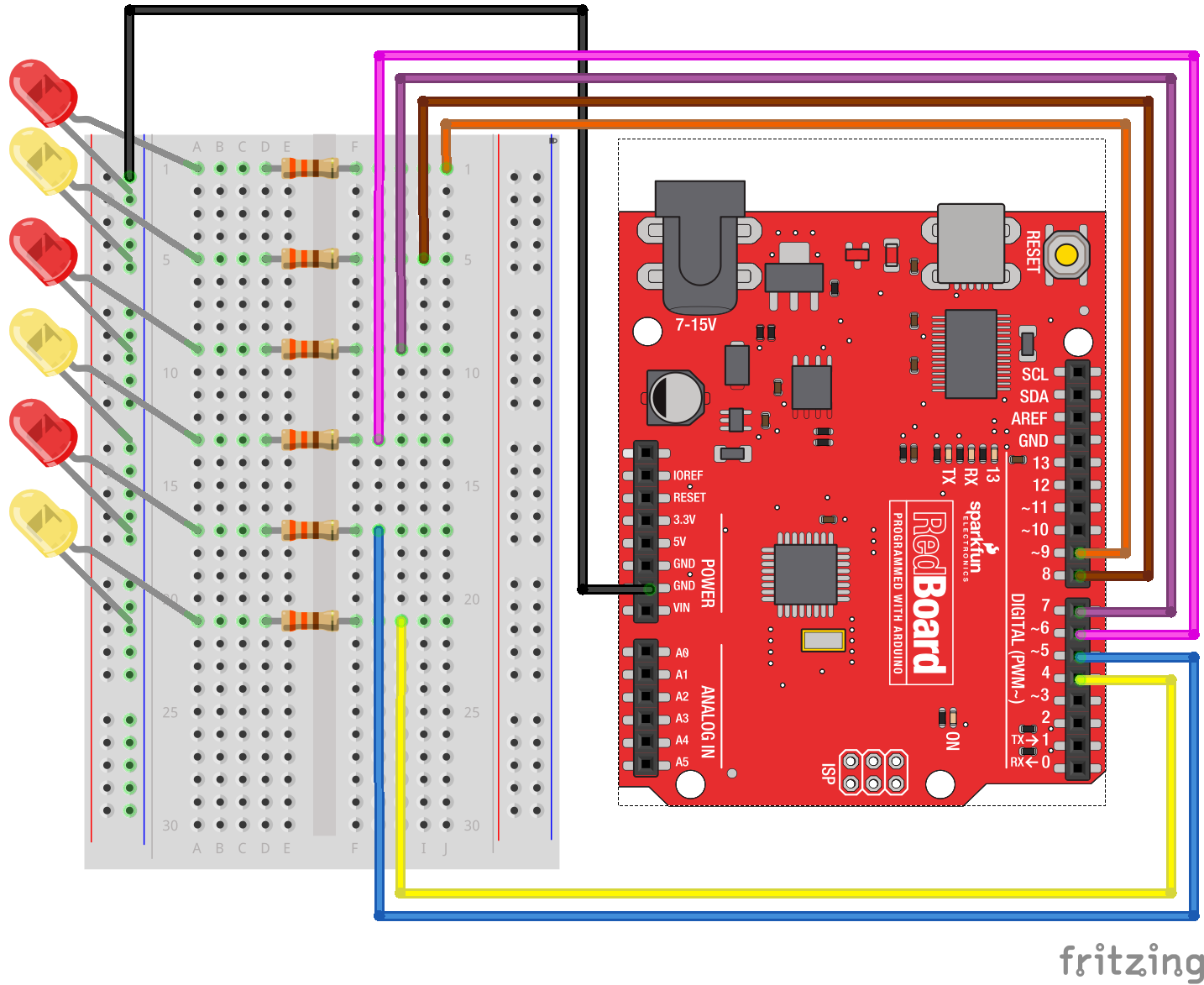
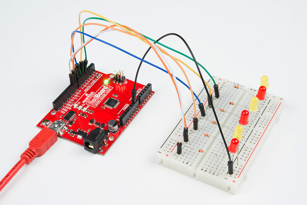
Experiment 4: Driving Multiple LEDs
Introduction
Now that you've gotten your LED to blink on and off, it's time to up the stakes a little bit – by connecting six LEDs at once. We'll also give your RedBoard a little test by creating various lighting sequences. This experiment is a great setup to start practicing writing your own programs and getting a feel for the way your RedBoard works.
Along with controlling the LEDs, you’ll learn a few programming tricks that keep your code neat and tidy!
You will need the following parts:
- 1x Breadboard
- 1x SparkFun RedBoard
- 6x LEDs
- 6x 330Ω Resistors
- 7x Jumper Wires
Didn't Get the Tinker Kit?
If you are conducting this experiment and didn't get the Tinker Kit, we suggest using these parts:
Hardware Hookup
Ready to start hooking everything up? Check out the wiring diagram and hookup table below to see how everything is connected.
| Polarized Components | Pay special attention to the component’s markings indicating how to place it on the breadboard. Polarized components can only be connected to a circuit in one direction. |
Wiring Diagram for the Experiment
Open the Sketch
Open the Arduino IDE software on your computer. Coding in the Arduino language will control your circuit.
You can type out or copy and paste the following code into the Arduino IDE. Hit upload, and see what happens!
language:cpp
/*
SparkFun Tinker Kit
Example sketch 04

MULTIPLE LEDs

  Make six LEDs dance. Dance LEDs, dance!


This sketch was written by SparkFun Electronics,
with lots of help from the Arduino community.
This code is completely free for any use.
Visit http://learn.sparkfun.com/products/2 for SIK information.
Visit http://www.arduino.cc to learn more about Arduino.
*/


// To keep track of all the LED pins, we'll use an "array."
// An array lets you store a group of variables, and refer to them
// by their position, or "index." Here we're creating an array of
// six integers, and initializing them to a set of values:
int ledPins[] = {4,5,6,7,8,9};


void setup()
{
  //create a local variable to store the index of which pin we want to control
  int index;


  // For the for() loop below, these are the three statements:

  //   1. index = 0;    Before starting, make index = 0.
  //   2. index <= 5;   If index is less or equal to 5, run the following code
  //   3. index++   Putting "++" after a variable means "add one to it".

  // When the test in statement 2 is finally false, the sketch
  // will continue.

  // This for() loop will make index = 0, then run the pinMode()
  // statement within the brackets. It will then do the same thing
  // for index = 2, index = 3, etc. all the way to index = 5.

  for(index = 0; index <= 5; index++)
  {
    pinMode(ledPins[index],OUTPUT);
  }
}


void loop()
{
  // This loop() calls functions that we've written further below.
  // We've disabled some of these by commenting them out (putting
  // "//" in front of them). To try different LED displays, remove
  // the "//" in front of the ones you'd like to run, and add "//"
  // in front of those you don't to comment out (and disable) those
  // lines.

  // Light up all the LEDs in turn
  oneAfterAnotherNoLoop();

  // Same as oneAfterAnotherNoLoop, but less typing
  //oneAfterAnotherLoop();

  // Turn on one LED at a time, scrolling down the line
  //oneOnAtATime();

  // Light the LEDs middle to the edges
  //pingPong();

  // Chase lights like you see on signs
  //marquee();

  // Blink LEDs randomly
  //randomLED();
}


/*
oneAfterAnotherNoLoop()
This function will light one LED, delay for delayTime, then light
the next LED, and repeat until all the LEDs are on. It will then
turn them off in the reverse order.
*/

void oneAfterAnotherNoLoop()
{
// time (milliseconds) to pause between LEDs
  int delayTime = 100;


  // turn all the LEDs on:

  digitalWrite(ledPins[0], HIGH);  //Turns on LED #0 (pin 4)
  delay(delayTime);                //wait delayTime milliseconds
  digitalWrite(ledPins[1], HIGH);  //Turns on LED #1 (pin 5)
  delay(delayTime);                //wait delayTime milliseconds
  digitalWrite(ledPins[2], HIGH);  //Turns on LED #2 (pin 6)
  delay(delayTime);                //wait delayTime milliseconds
  digitalWrite(ledPins[3], HIGH);  //Turns on LED #3 (pin 7)
  delay(delayTime);                //wait delayTime milliseconds
  digitalWrite(ledPins[4], HIGH);  //Turns on LED #4 (pin 8)
  delay(delayTime);                //wait delayTime milliseconds
  digitalWrite(ledPins[5], HIGH);  //Turns on LED #5 (pin 9)
  delay(delayTime);                //wait delayTime milliseconds

  // turn all the LEDs off:

  digitalWrite(ledPins[5], LOW);   //Turn off LED #5 (pin 9)
  delay(delayTime);                //wait delayTime milliseconds
  digitalWrite(ledPins[4], LOW);   //Turn off LED #4 (pin 8)
  delay(delayTime);                //wait delayTime milliseconds
  digitalWrite(ledPins[3], LOW);   //Turn off LED #3 (pin 7)
  delay(delayTime);                //wait delayTime milliseconds
  digitalWrite(ledPins[2], LOW);   //Turn off LED #2 (pin 6)
  delay(delayTime);                //wait delayTime milliseconds
  digitalWrite(ledPins[1], LOW);   //Turn off LED #1 (pin 5)
  delay(delayTime);                //wait delayTime milliseconds
  digitalWrite(ledPins[0], LOW);   //Turn off LED #0 (pin 4)
  delay(delayTime);                //wait delayTime milliseconds
}


/*
oneAfterAnotherLoop()

This function does exactly the same thing as oneAfterAnotherNoLoop(),
but it takes advantage of for() loops and the array to do it with
much less typing.
*/

void oneAfterAnotherLoop()
{
  int index;
  int delayTime = 100; // milliseconds to pause between LEDs
                       // make this smaller for faster switching

  // Turn all the LEDs on:

  // This for() loop will step index from 0 to 5
  // (putting "++" after a variable means add one to it)
  // and will then use digitalWrite() to turn that LED on.

  for(index = 0; index <= 5; index++)
  {
    digitalWrite(ledPins[index], HIGH);
    delay(delayTime);
  }

  // Turn all the LEDs off:

  // This for() loop will step index from 5 to 0
  // (putting "--" after a variable means subtract one from it)
  // and will then use digitalWrite() to turn that LED off.

  for(index = 5; index >= 0; index--)
  {
    digitalWrite(ledPins[index], LOW);
    delay(delayTime);
  }
}


/*
oneOnAtATime()

This function will step through the LEDs,
lighting only one at at time.
*/

void oneOnAtATime()
{
  int index;
  int delayTime = 100; // milliseconds to pause between LEDs
                       // make this smaller for faster switching

  // step through the LEDs, from 0 to 5

  for(index = 0; index <= 5; index++)
  {
    digitalWrite(ledPins[index], HIGH);  // turn LED on
    delay(delayTime);                    // pause to slow down
    digitalWrite(ledPins[index], LOW);   // turn LED off
  }
}


/*
pingPong()

This function will step through the LEDs,
lighting one at at time in both directions.
*/

void pingPong()
{
  int index;
  int delayTime = 100; // milliseconds to pause between LEDs
                       // make this smaller for faster switching

  // step through the LEDs, from 0 to 5

  for(index = 0; index <= 5; index++)
  {
    digitalWrite(ledPins[index], HIGH);  // turn LED on
    delay(delayTime);                    // pause to slow down
    digitalWrite(ledPins[index], LOW);   // turn LED off
  }

  // step through the LEDs, from 5 to 0

  for(index = 5; index >= 0; index--)
  {
    digitalWrite(ledPins[index], HIGH);  // turn LED on
    delay(delayTime);                    // pause to slow down
    digitalWrite(ledPins[index], LOW);   // turn LED off
  }
}


/*
marquee()

This function will mimic "chase lights" like those around signs.
*/

void marquee()
{
  int index;
  int delayTime = 200; // milliseconds to pause between LEDs
                       // Make this smaller for faster switching

  // Step through the first four LEDs
  // (We'll light up one in the lower 3 and one in the upper 3)

  for(index = 0; index <= 2; index++) // Step from 0 to 3
  {
    digitalWrite(ledPins[index], HIGH);    // Turn a LED on
    digitalWrite(ledPins[index+3], HIGH);  // Skip four, and turn that LED on
    delay(delayTime);                      // Pause to slow down the sequence
    digitalWrite(ledPins[index], LOW);     // Turn the LED off
    digitalWrite(ledPins[index+3], LOW);   // Skip four, and turn that LED off
  }
}


/*
randomLED()

This function will turn on random LEDs. Can you modify it so it
also lights them for random times?
*/

void randomLED()
{
  int index;
  int delayTime;

  // The random() function will return a semi-random number each
  // time it is called. See http://arduino.cc/en/Reference/Random
  // for tips on how to make random() even more random.

  index = random(5);    // pick a random number between 0 and 5
  delayTime = 100;

  digitalWrite(ledPins[index], HIGH);  // turn LED on
  delay(delayTime);                    // pause to slow down
  digitalWrite(ledPins[index], LOW);   // turn LED off
}
Code to Note
int ledPins[] = {4,5,6,7,8,9};
When you have to manage a lot of variables, an "array" is a handy way to group them together. Here we're creating an array of integers, called ledPins, with six elements. Each element is referenced by its index. The first element is the index of [0].
digitalWrite(ledPins[0], HIGH);
You refer to the elements in an array by their position. The first element is at position 0, the second is at position 1, etc. You refer to an element using "ledPins[x]" where x is the position. Here we're making digital pin 4 HIGH, since the array element at position 0 is "4."
index = random(5);
Computers like to do the same things each time they run. But sometimes you want to do things randomly, such as simulating the roll of a dice. The random() function is a great way to do this.
See http://arduino.cc/en/reference/random for more information.
What You Should See
This is similar to Experiment 1, but instead of one LED, you should see all the LEDs blink. If they don't, make sure you have assembled the circuit correctly and verified and uploaded the code to your board, or see the Troubleshooting section.
Troubleshooting
Some LEDs Fail to Light
It is easy to insert an LED backward. Check the LEDs that aren't working and ensure they are in the correct orientation.
Operating out of Sequence
With eight wires it's easy to cross a couple. Double check that the first LED is plugged into pin 4 and each pin thereafter.
Starting Fresh
It’s easy to accidentally misplace a wire without noticing. Pulling everything out and starting with a fresh slate is often easier than trying to track down the problem.
Experiment 5: Reading a Button Press
Introduction
Up until now, we’ve focused mostly on outputs. Now we’re going to go to the other end of the spectrum and play around with inputs. In Experiment 2, we used an analog input to read the potentiometer. In this experiment, we’ll be reading one of the most common and simple inputs – a push button – by using a digital input. We will use it to cycle through different colors on the RGB.
Parts Needed
You will need the following parts:
- 1x Breadboard
- 1x SparkFun RedBoard
- 1x RGB LED
- 3x 330Ω Resistor
- 8x Jumper Wires
- 1x Push Button
- 1x 10K Resistors
Didn't Get the Tinker Kit?
If you are conducting this experiment and didn't get the Tinker Kit, we suggest using these parts:
Suggested Reading
Before continuing with this experiment, we recommend you be somewhat familiar with the concepts in these tutorials:
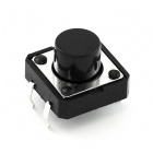
Introducing the Push Button
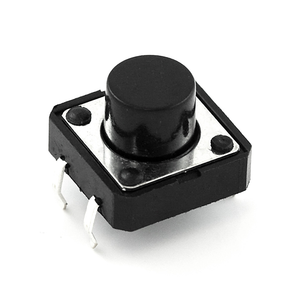
A momentary push button closes or completes the circuit only while it is being pressed. The button has four pins, which are broken out into two sets of two pins. When you press down on the button and get a nice "click," the button bridges the two sets of pins and allows current to flow through the circuit.
How do you know which pins are paired up? The buttons included in this kit will only fit across the breadboard ditch in one direction. Once you get the button pressed firmly into the breadboard (across the ditch), the pins are horizontally paired. The pins toward the top of the breadboard are connected, and the pins toward the button of the breadboard are connected.
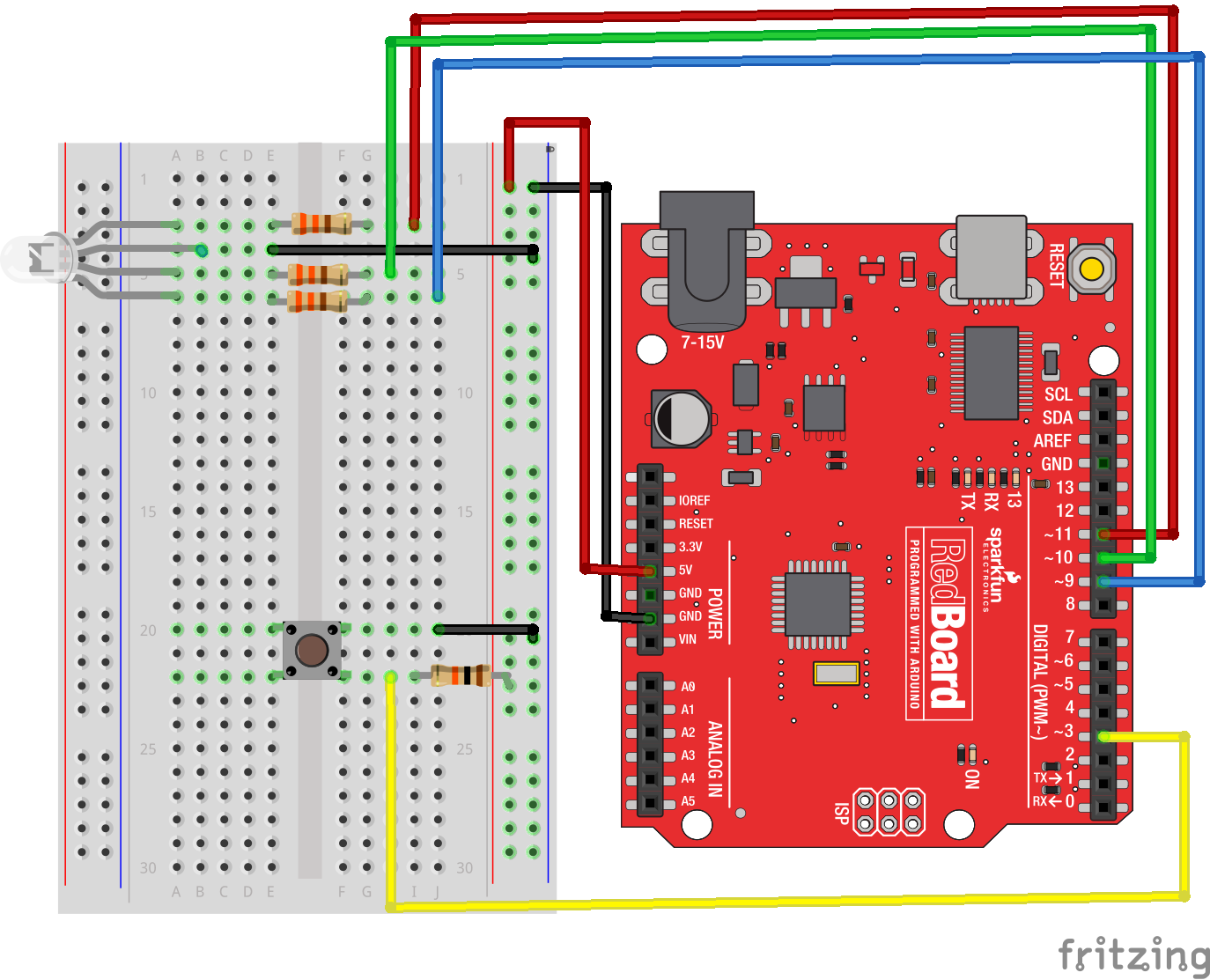
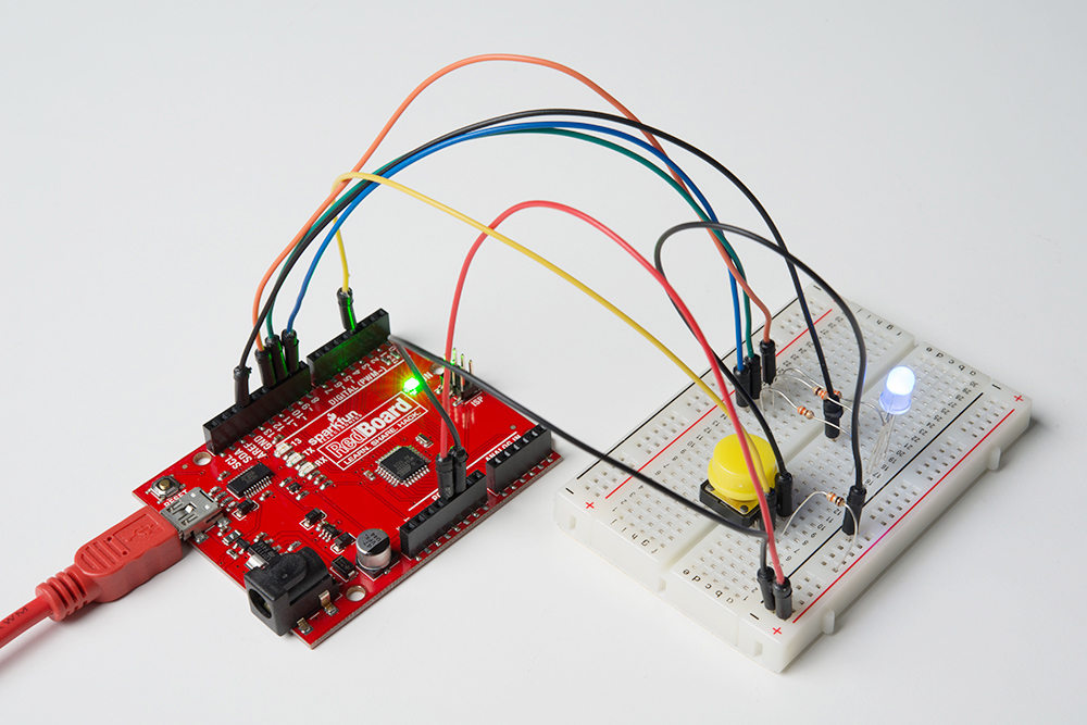
Hardware Hookup
Ready to start hooking everything up? Check out the wiring diagram and hookup table below to see how everything is connected.
| Polarized Components | Pay special attention to the component’s markings indicating how to place it on the breadboard. Polarized components can only be connected to a circuit in one direction. |
Wiring Diagram for the Experiment
Digital Input
Previously we've used the analog pins for input; now we'll use the digital pins for input as well. Because digital pins only know about HIGH and LOW signals, they're perfect for interfacing to pushbuttons and switches that also only have "on" and "off" states.
We'll connect one side of the pushbutton to ground, and the other side to a digital pin. When we press down on the pushbutton, the pin will be connected to ground, and therefore will be read as "LOW" by the RedBoard.
But wait -- what happens when you're not pushing the button? In this state, the pin is disconnected from everything, which we call "floating." What will the pin read as, then -- HIGH or LOW? It's hard to say, because there's no solid connection to either 5V or ground. The pin could read as either one.
To deal with this issue, we'll connect a small (10K, or 10,000 Ohm) resistance between the signal pin and 5V. This "pull-up" resistor will ensure that when you're NOT pushing the button, the pin will still have a weak connection to 5 volts, and therefore read as HIGH.
Open the Sketch
Open the Arduino IDE software on your computer. Coding in the Arduino language will control your circuit.
You can type out or copy and paste the following code into the Arduino IDE. Hit upload, and see what happens!
language:cpp
/*
SparkFun Tinker Kit
Example sketch 05

PUSH BUTTONS

  Use pushbuttons for digital input

This sketch was written by SparkFun Electronics,
with lots of help from the Arduino community.
This code is completely free for any use.
Visit http://learn.sparkfun.com/products/2 for SIK information.
Visit http://www.arduino.cc to learn about Arduino.

*/


// First we'll set up constants for the pin numbers.
// This will make it easier to follow the code below.

 // pushbutton pin
 const int buttonPin = 3;

 //RGB LED pins
 const int redPin = 11;
 const int greenPin = 10;
 const int bluePin = 9;


//create a variable to store a counter and set it to 0
int counter = 0;
void setup()
{
  // Set up the pushbutton pins to be an input:
  pinMode(buttonPin, INPUT);

  // Set up the RGB pins to be an outputs:
  pinMode(redPin, OUTPUT);
  pinMode(greenPin,OUTPUT);
  pinMode(bluePin,OUTPUT);
}


void loop()
{
 // local variable to hold the pushbutton states
  int buttonState;

  //read the digital state of buttonPin with digitalRead() function and store the           //value in buttonState variable
  buttonState = digitalRead(buttonPin);

  //if the button is pressed increment counter and wait a tiny bit to give us some          //time to release the button
  if (buttonState == LOW) // light the LED
  {
    counter++;
    delay(150);
  }

  //use the if satement to check the value of counter. If counter is equal to 0 all         //pins are off
  if(counter == 0)
  {
   digitalWrite(redPin,LOW);
   digitalWrite(greenPin,LOW);
   digitalWrite(bluePin,LOW);
  }

  //else if counter is equal to 1, redPin is HIGH
  else if(counter == 1)
  {
   digitalWrite(redPin,HIGH);
   digitalWrite(greenPin,LOW);
   digitalWrite(bluePin,LOW);
  }

  //else if counter is equal to 2 greenPin is HIGH
  else if(counter ==2)
  {
   digitalWrite(redPin,LOW);
   digitalWrite(greenPin,HIGH);
   digitalWrite(bluePin,LOW);
  }

  //else if counter is equal to 3 bluePin is HIGH
  else if(counter ==3)
  {
   digitalWrite(redPin,LOW);
   digitalWrite(greenPin,LOW);
   digitalWrite(bluePin,HIGH);
  }

  //else reset the counter to 0 (which turns all pins off)
  else
  {
   counter =0;
  }
}
Code to Note
pinMode(buttonPin, INPUT);
The digital pins can be used as inputs as well as outputs. Before you do either, you need to tell the Arduino which direction you're going.
buttonState = digitalRead(buttonPin);
To read a digital input, you use the digitalRead() function. It will return HIGH if there's 3.3V present at the pin, or LOW if there's 0V present at the pin.
if (button1State == LOW)
Because we've connected the button to GND, it will read LOW when it's being pressed. Here we're using the "equivalence" operator ("==") to see if the button is being pressed.
What You Should See
You should see the LED turn on one color if you press the button. If you continue to press the button, the LED will change colors. (See the code to find out why!) If it isn't working, make sure you have assembled the circuit correctly and verified and uploaded the code to your board, or see the Troubleshooting section.
Troubleshooting
Light Not Turning On
The pushbutton is square, and because of this it is easy to put it in the wrong way. Give it a 90 degree twist and see if it starts working.
Underwhelmed
No worries; these circuits are all super stripped-down to make playing with the components easy, but once you throw them together the sky is the limit.
Experiment 6: Reading a Photoresistor
Introduction
In Experiment 2, you got to use a potentiometer, which varies resistance based on the twisting of a knob and, in turn, changes the voltage being read by the analog input pin. In this circuit you’ll be using a photoresistor, which changes resistance based on how much light the sensor receives. You will read the light value of the room and have an LED turn on if it is dark and turn off if it is bright. That's right; you are going to build a night light!
Parts Needed
You will need the following parts:
- 1x Breadboard
- 1x SparkFun RedBoard
- 1x LED
- 1x 330Ω Resistor
- 7x Jumper Wires
- 1x Photoresistor
- 1x 10K Resistor
Didn't Get the Tinker Kit?
If you are conducting this experiment and didn't get the Tinker Kit, we suggest using these parts:

Introducing the Photoresistor
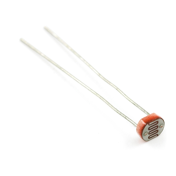
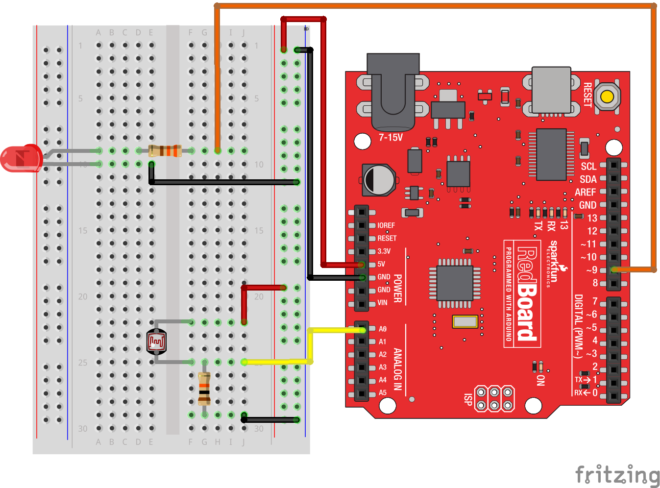
The photoresistor changes its resistance based on the light to which it is exposed. To use this with the RedBoard, you will need to build a voltage divider with a 10K Ohm resistor as shown in the wiring diagram for this experiment. The 101 board cannot read a change in resistance, only a change in voltage. A voltage divider allows you to translate a change in resistance to a corresponding voltage value.
The voltage divider enables the use of resistance-based sensors like the photoresistor in a voltage-based system. As you explore different sensors, you will find more resistance-based sensors that only have two pins like the photoresistor. To use them with your RedBoard you will need to build a voltage divider like the one in this experiment. To learn more about resistors in general, check out our tutorial on resistors and also our tutorial on voltage dividers.
Hardware Hookup
Ready to start hooking everything up? Check out the wiring diagram below to see how everything is connected.
| Polarized Components | Pay special attention to the component’s markings indicating how to place it on the breadboard. Polarized components can only be connected to a circuit in one direction. |
Wiring Diagram for the Experiment
Open the Sketch
Open the Arduino IDE software on your computer. Coding in the Arduino language will control your circuit.
You can type out or copy and paste the following code into the Arduino IDE. Hit upload, and see what happens!
language:cpp
/*
SparkFun Tinker Kit
Example sketch 06

PHOTORESISTOR

  Read a photoresistor (light sensor) to detect "darkness" and turn on an LED when it is "dark" and turn back off again when it is "bright."

This sketch was written by SparkFun Electronics,
with lots of help from the Arduino community.
This code is completely free for any use.
Visit http://learn.sparkfun.com/products/2 for SIK information.
Visit http://www.arduino.cc to learn more about Arduino.
*/


// As usual, we'll create constants to name the pins we're using.
// This will make it easier to follow the code below.

const int sensorPin = 0;
const int ledPin = 9;

// We'll also set up some global variables for the light level a calibration value and     //and a raw light value
int lightCal;
int lightVal;


void setup()
{
  // We'll set up the LED pin to be an output.
  pinMode(ledPin, OUTPUT);
  lightCal = analogRead(sensorPin);
  //we will take a single reading from the light sensor and store it in the lightCal        //variable. This will give us a prelinary value to compare against in the loop
}


void loop()
{
  //Take a reading using analogRead() on sensor pin and store it in lightVal
  lightVal = analogRead(sensorPin);


  //if lightVal is less than our initial reading (lightCal) minus 50 it is dark and         //turn pin 9 HIGH. The (-50) part of the statement sets the sensitivity. The smaller       //the number the more sensitive the circuit will be to variances in light.
  if(lightVal < lightCal - 50)
  {
    digitalWrite(9,HIGH);
  }

  //else, it is bright, turn pin 9 LOW
  else
  {
    digitalWrite(9,LOW);
  }

}
Code to Note
lightCal = analogRead(sensorPin); lightCal is a calibration variable. Your RedBoard takes a single reading of the light sensor in the setup and uses this value to compare against the lightVal in the loop. This value doesn't change in the loop, as it is set in the setup function. To update this value you can press the RESET button or power cycle the board.
if(lightVal < lightCal -50) If the light value variable that is constantly being updated in the loop is less than the calibration value set in the setup minus 50, it is dark and the LED should turn on. The (-50) portion of this statement is a sensitivity value. The higher the value, the less sensitive the circuit will be; the lower the value, the more sensitive it will be to lighting conditions.
What You Should See
You should see the LED turn on when it is darker and turn off when it is brighter. Try putting your hand over the sensor and then removing it. If it isn't working, make sure you have assembled the circuit correctly and verified and uploaded the code to your board, or see the Troubleshooting section.

Troubleshooting
LED Remains Dark
You may have been casting a shadow over the sensor when you uploaded your code. Make sure the sensor is exposed to the ambient light of the room and press the MASTER RESET button or re-upload your code. This will reset the calibration value in the setup.
Still Not Quite Working
You may have your logical statement wrong. Double check your code and try adjusting the sensitivity level a little lower or higher. Make sure there is no semicolon after the if() statement. This is a common error and a tricky one to find!
Experiment 7: Reading a Temperature Sensor
Introduction
A temperature sensor is exactly what it sounds like – a sensor used to measure ambient temperature. In this experiment you will read the raw 0--1023 value from the temperature sensor, calculate the actual temperature, and then print it out over the serial monitor. Don't know what the serial monitor is? Go through this experiment to find out!
Parts Needed
You will need the following parts:
- 1x Breadboard
- 1x SparkFun RedBoard
- 3x Jumper Wires
- 1x TMP36 Temperature Sensor
Didn't Get the Tinker Kit?
If you are conducting this experiment and didn't get the Tinker Kit, we suggest using these parts:
Introducing the TMP36 Temperature Sensor
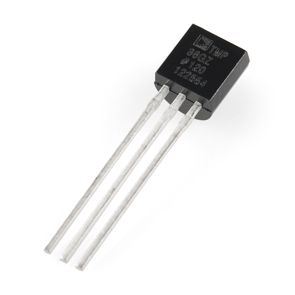
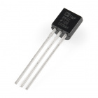
The TMP36 is a low-voltage, precision centigrade temperature sensor. It provides a voltage output that is linearly proportional to the Celsius temperature. It also doesn’t require any external calibration to provide typical accuracies of ±1°C at +25°C and ±2°C over the −40°C to +125°C temperature range. The output voltage can easily convert to temperature using the scale factor of 10 mV/°C.
If you are looking at the flat face with text on it, the center pin is your signal pin; the left-hand pin is supply voltage (5V in this tutorial), and the right-hand pin connects to ground.
Hardware Hookup
Ready to start hooking everything up? Check out the wiring diagram below to see how everything is connected.
| Polarized Components | Pay special attention to the component’s markings indicating how to place it on the breadboard. Polarized components can only be connected to a circuit in one direction. |
Please note: The temperature sensor can only be connected to a circuit in one direction. See below for the pin outs of the temperature sensor -- TMP36.
Wiring Diagram for the Experiment

Open the Sketch
Open the Arduino IDE software on your computer. Coding in the Arduino language will control your circuit.
You can type out or copy and paste the following code into the Arduino IDE. Hit upload, and see what happens!
language:cpp
/*
SparkFun Tinker Kit
Example sketch 07

TEMPERATURE SENSOR

  Use the "serial monitor" window to read a temperature sensor.

This sketch was written by SparkFun Electronics,
with lots of help from the Arduino community.
This code is completely free for any use.
Visit http://learn.sparkfun.com/products/2 for SIK information.
Visit http://www.arduino.cc to learn more about Arduino.

*/

//analog input pin constant
const int tempPin = 0;

//raw reading variable
int tempVal;

//voltage variable
float volts;

//final temperature variables
float tempC;
float tempF;

void setup()
{
  // start the serial port at 9600 baud
  Serial.begin(9600);
}


void loop()
{
 //read the temp sensor and store it in tempVal
 tempVal = analogRead(tempPin);

 //print out the 10 value from analogRead
 Serial.print("TempVal = ");
 Serial.print(tempVal);

 //print a spacer
 Serial.print(" **** ");

 //converting that reading to voltage by multiplying the reading by 5V (voltage of       //the RedBoard)
 volts = tempVal * 5;
 volts /= 1023.0;

 //print out the raw voltage over the serial port
 Serial.print("volts: ");
 Serial.print(volts, 3);

 //print out divider
 Serial.print(" **** ");

 //calculate temperature celsius from voltage
 //equation found on the sensor spec.
 tempC = (volts - 0.5) * 100 ;

// print the celcius temperature over the serial port
Serial.print(" degrees C: ");
Serial.print(tempC);

//print spacer
 Serial.print(" **** ");

// Convert from celcius to fahrenheit
tempF = (tempC * 9.0 / 5.0) + 32.0;

//print the fahrenheit temperature over the serial port
Serial.print(" degrees F: ");
Serial.println(tempF);

//wait a bit before taking another reading
delay(1000);
}
Code to Note
Serial.begin(9600);
Before using the serial monitor, you must call Serial.begin() to initialize it. 9600 is the "baud rate," or communications speed. When two devices are communicating with each other, both must be set to the same speed.
Serial.print(tempC);
The Serial.print() command is very smart. It can print out almost anything you can throw at it, including variables of all types, quoted text (AKA "strings"), etc. See http://arduino.cc/en/serial/print for more info.
Serial.println(tempF);
Serial.print() will print everything on the same line.
Serial.println() will move to the next line. By using both of these commands together, you can create easy-to-read printouts of text and data.
What You Should See
You should be able to read the temperature your temperature sensor is detecting on the serial monitor in the Arduino IDE. If it isn't working, make sure you have assembled the circuit correctly and verified and uploaded the code to your board, or see the Troubleshooting section.
Example of what you should see in the Arduino IDE’s serial monitor:
TempVal = 223 **** volts: 0.719 **** degrees C: 21.94 **** degrees F: 71.48
TempVal = 224 **** volts: 0.723 **** degrees C: 22.26 **** degrees F: 72.06
TempVal = 224 **** volts: 0.723 **** degrees C: 22.26 **** degrees F: 72.06
TempVal = 224 **** volts: 0.723 **** degrees C: 22.26 **** degrees F: 72.06
TempVal = 224 **** volts: 0.723 **** degrees C: 22.26 **** degrees F: 72.06
TempVal = 224 **** volts: 0.723 **** degrees C: 22.26 **** degrees F: 72.06
TempVal = 223 **** volts: 0.719 **** degrees C: 21.94 **** degrees F: 71.48
TempVal = 223 **** volts: 0.719 **** degrees C: 21.94 **** degrees F: 71.48

Troubleshooting
Nothing Seems to Happen
This program has no outward indication it is working. To see the results you must open the Arduino IDE's serial monitor (instructions on previous page).
Gibberish is Displayed
This happens because the serial monitor is receiving data at a different speed than expected. To fix this, click the pull-down box that reads "*** baud" and change it to "9600 baud".
Temperature Value is Unchanging
Try pinching the sensor with your fingers to heat it up or pressing a bag of ice against it to cool it down.
Temperature Sensor is Really Hot!
You have wired it backward! Unplug your Arduino immediately, let the sensor cool down, and double check your wiring. If you catch it soon enough your sensor may not have been damaged and may still work.
Experiment 8: Using a Servo Motor
Introduction
This experiment is your introduction to the servo motor, which is a smart motor that you can tell to rotate to a specific angular location. You will program it to rotate to a series of locations, then sweep across its full range of motion, and then repeat.
Parts Needed
You will need the following parts:
- 1x Breadboard
- 1x SparkFun RedBoard
- 1x Servo
- 3x Jumper Wires
Didn't Get the Tinker Kit?
If you are conducting this experiment and didn't get the Tinker Kit, we suggest using these parts:

Suggested Reading
Before continuing with this experiment, we recommend you be familiar with the concepts in the following tutorial:
Introducing the Servo Motor

Unlike the action of most motors that continuously rotate, a servo motor can rotate to and hold a specific angle until it is told to rotate to a different angle. You can control the angle of the servo by sending it a PWM (Pulse Width Modulation) pulse train; the PWM signal is mapped to a specific angle from 0 to 180 degrees.
Inside of the servo there is a gearbox connected to a motor that drives the shaft. There is also a potentiometer that gives feedback on the rotational position of the servo, which is then compared to the incoming PWM signal. The servo adjusts accordingly to match the two signals.
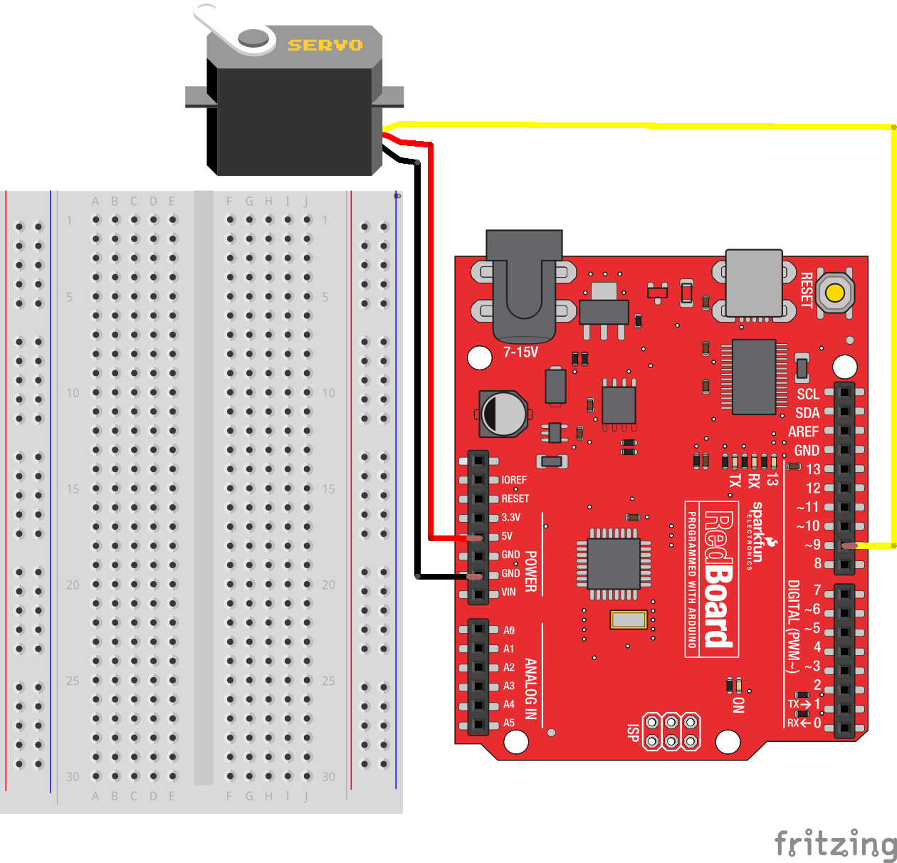
In this experiment, the servo is powered through 5 volts on the red wire, ground on the black wire, and the white wire is connected to a digital GPIO (General Purpose Input/Output) pin on which you can use PWM (11, 10, 9, 6, 5 and 3 on the RedBoard).
Hardware Hookup
Ready to start hooking everything up? Check out the wiring diagram below to see how everything is connected.
| Polarized Components | Pay special attention to the component’s markings indicating how to place it on the breadboard. Polarized components can only be connected to a circuit in one direction. |
Connect 3x jumper wires to the female 3-pin header on the servo. This will make it easier to breadboard the servo.
Wiring Diagram for the Experiment
Open the Sketch
Open the Arduino IDE software on your computer. Coding in the Arduino language will control your circuit.
You can type out or copy and paste the following code into the Arduino IDE. Hit upload, and see what happens!
language:cpp
/*
SparkFun Tinker Kit
Example sketch 08

SINGLE SERVO

  Sweep a servo back and forth through its full range of motion.

This sketch was written by SparkFun Electronics,
with lots of help from the Arduino community.
This code is completely free for any use.
Visit http://learn.sparkfun.com/products/2 for SIK information.
Visit http://www.arduino.cc to learn more about Arduino.
*/

//include the servo library
#include <Servo.h>

//create a servo object called servo1
Servo servo1;


void setup()
{
  //attach servo1 to pin 9 on the Arduino 101
  servo1.attach(9);
}


void loop()
{
  //create a local variable to store the servo's position.
  int position;

  // To control a servo, you give it the angle you'd like it
  // to turn to. Servos cannot turn a full 360 degrees, but you
  // can tell it to move anywhere between 0 and 180 degrees.

  // Change position at full speed:

  // Tell servo to go to 90 degrees
  servo1.write(90);

  // Pause to get it time to move
  delay(1000);

  // Tell servo to go to 180 degrees
  servo1.write(180);

  // Pause to get it time to move
  delay(1000);

  // Tell servo to go to 0 degrees
  servo1.write(0);

  // Pause to get it time to move
  delay(1000);


  // Tell servo to go to 180 degrees, stepping by two degrees
  for(position = 0; position < 180; position += 2)
  {
  // Move to next position
    servo1.write(position);
     // Short pause to allow it to move
    delay(20);
  }

  // Tell servo to go to 0 degrees, stepping by one degree
  for(position = 180; position >= 0; position -= 1)
  {
    // Move to next position
    servo1.write(position);
    // Short pause to allow it to move
    delay(20);
  }
}
Code to Note
#include <Servo.h>
#include is a special "preprocessor" command that inserts a library (or any other file) into your sketch. You can type this command yourself, or choose an installed library from the "sketch / import library" menu.
Servo servo1;
When you use a library, you create what is called an object of that library and name it. This object is a Servo library object, and it is named servo1. If you were using multiple servos you would name each one in this way.
servo1.attach(9);
The Servo library adds new commands that let you control a servo. To prepare the RedBoard to control a servo, you must first create a Servo "object" for each servo (here we've named it "servo1"), and then "attach" it to a digital pin (here we're using pin 9). Think of this as the servo's way of calling a pinMode() function.
servo1.write(180);
The servos in this kit don't spin all the way around, but they can be commanded to move to a specific position. We use the Servo library's write() command to move a servo a specified number of degrees (0 to 180). Remember that the servo requires time to move, so give it a short delay() if necessary.
What You Should See
You should see your servo motor move to various locations at several speeds. If the motor doesn't move, check your connections and make sure you have verified and uploaded the code, or see the Troubleshooting section.

Troubleshooting
Servo Not Twisting
Even with colored wires it is still shockingly easy to plug a servo in backward. This might be the case.
Still Not Working
A mistake we made a time or two was simply forgetting to connect the power (red and black wires) to 5 volts and ground (GND).
Fits and Starts
If the servo begins moving, then twitches, and there's a flashing light on your RedBoard, the power supply you are using is not quite up to the challenge. Using a wall adapter instead of USB should solve this problem.
Experiment 9: Driving a Motor with an H-Bridge
Introduction
How could you make a motor spin in different directions? With an H-Bridge! In this experiment you will use the H-Bridge to control the motor's direction and speed.
Parts Needed
You will need the following parts:
- 1x Breadboard
- 1x SparkFun RedBoard
- 1x SN754410 H-Bridge IC
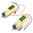
- 1x 48:1 Geared Motor
- 12x Jumper Wires
Didn't Get the Tinker Kit?
If you are conducting this experiment and didn't get the Tinker Kit, we suggest using these parts:


Introducing the H-Bridge
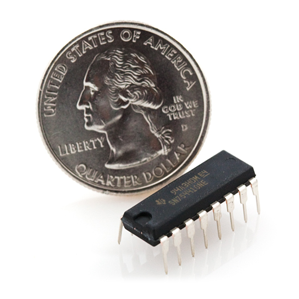
The SN754410 is an Integrated Circuit (IC), called an H-Bridge, that makes controlling motors easier. An H-Bridge allows you to control both the direction and the amount of an electrical current being supplied to a motor. You can think of it as a smart valve that allows you to change the direction of the current passing through the motor.
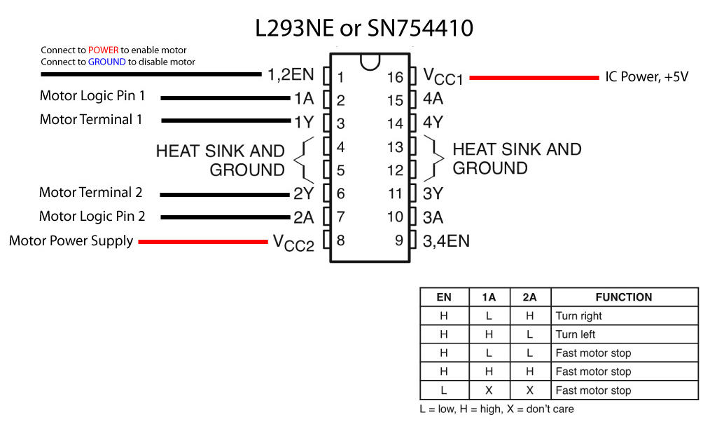
To switch the direction of the current, you use two pins to toggle pins on the board either HIGH or LOW. If the two direction pins are both HIGH or LOW at the same time, that causes the board to brake the motors. If one pin is HIGH and the other is LOW, the motor spins in one direction. If you flip-flop the states, the motor spins in the opposite direction. The IC is also powered separately with 5V supplied to pin 16 on the IC, and up to 36V for the motor voltage on pin 8 of the IC.
You can control up to two motors with a single IC. You can use this diagram as a reference for pin numbers in conjunction with the table below.
Hookup Table
| 1 | PWM signal for controlling the speed of motor A |
| 2 | Direction pin 1 for motor A |
| 3 | Motor A connection 1 |
| 4 | Ground / Heat Sink |
| 5 | Ground / Heat Sink |
| 6 | Motor A connection 2 |
| 7 | Direction pin 2 for motor A |
| 8 | Motor supply voltage |
| 9 | PWM signal for controlling the speed of motor B |
| 10 | Direction pin 1 for motor B |
| 11 | Motor B connection 1 |
| 12 | Ground / Heat Sink |
| 13 | Ground / Heat Sink |
| 14 | Motor B connection 2 |
| 15 | Direction pin 2 for motor B |
| 16 | Chip voltage (5V) |
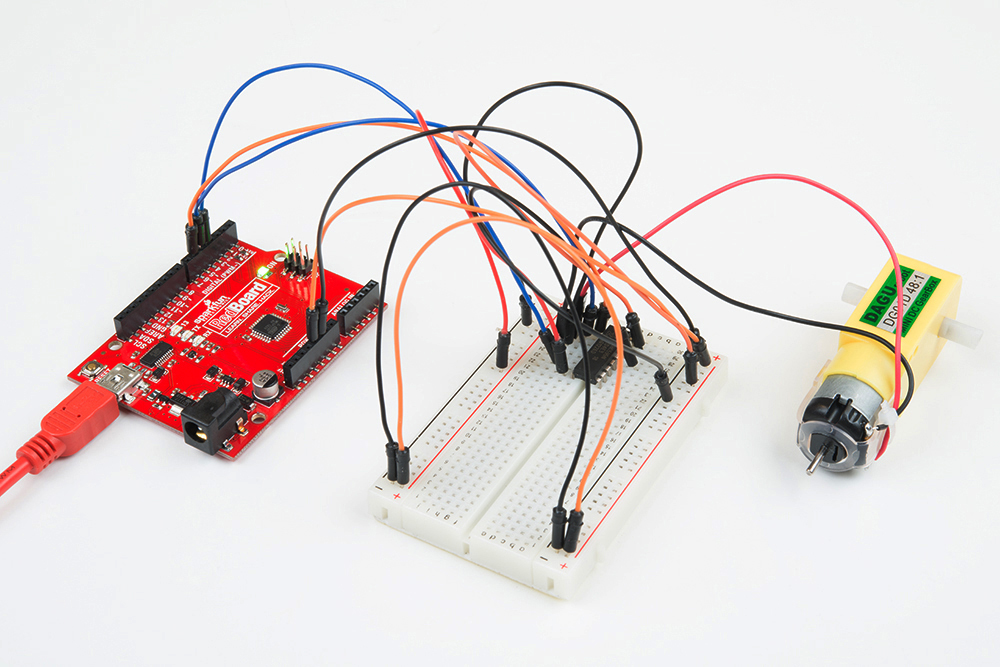
Hardware Hookup
Ready to start hooking everything up? Check out the wiring diagram below to see how everything is connected.
| Polarized Components | Pay special attention to the component’s markings indicating how to place it on the breadboard. Polarized components can only be connected to a circuit in one direction. |
Wiring Diagram for the Experiment

Open the Sketch
Open the Arduino IDE software on your computer. Coding in the Arduino language will control your circuit.
You can type out or copy and paste the following code into the Arduino IDE. Hit upload, and see what happens!
language:cpp
/*
SparkFun Tinker Kit
Example sketch 9

SparkFun Motor Driver

Use the SparkFun Motor Driver to control the speed and direction of a motor

This sketch was written by SparkFun Electronics,
with lots of help from the Arduino community.
This code is completely free for any use.
Visit http://learn.sparkfun.com/products/2 for SIK information.
Visit http://www.arduino.cc to learn more about Arduino.
*/

//define the two direction logic pins and the speed / PWM pin
const int DIR_A = 5;
const int DIR_B = 4;
const int PWM = 6;

void setup()
{
//set all pins as output
pinMode(DIR_A, OUTPUT);
pinMode(DIR_B, OUTPUT);
pinMode(PWM, OUTPUT);
}

void loop()
{
 //drive forward at full speed by pulling DIR_A High
 //and DIR_B low, while writing a full 255 to PWM to
 //control speed
 digitalWrite(DIR_A, HIGH);
 digitalWrite(DIR_B, LOW);
 analogWrite(PWM, 255);

 //wait 1 second
 delay(1000);

 //Brake the motor by pulling both direction pins to
 //the same state (in this case LOW). PWM doesn't matter
 //in a brake situation, but set as 0.
 digitalWrite(DIR_A, LOW);
 digitalWrite(DIR_B, LOW);
 analogWrite(PWM, 0);

 //wait 1 second
 delay(1000);

 //change direction to reverse by flipping the states
 //of the direction pins from their forward state
 digitalWrite(DIR_A, LOW);
 digitalWrite(DIR_B, HIGH);
 analogWrite(PWM, 150);

 //wait 1 second
 delay(1000);

 //Brake again
 digitalWrite(DIR_A, LOW);
 digitalWrite(DIR_B, LOW);
 analogWrite(PWM, 0);

 //wait 1 second
 delay(1000);
 }
Code to Note
language:cpp
digitalWrite(DIR_A, HIGH);
digitalWrite(DIR_B, LOW);
analogWrite(PWM, 255);
The Motor Driver uses a control logic that works by pulling certain pins HIGH or LOW (pins 4 and 5 in this case) to change the direction of the motor's rotation and then send a PWM signal to pin 6 to control the speed. This chunk of code runs to motor in one direction at full speed.
language:cpp
digitalWrite(DIR_A, LOW);
digitalWrite(DIR_B, HIGH);
analogWrite(PWM, 150);
This chunk of code is similar, but changes the direction by flipping the direction pin's state and setting the PWM pin at a slower speed.
language:cpp
digitalWrite(DIR_A, LOW);
digitalWrite(DIR_B, LOW);
analogWrite(PWM, 0);
This final chunk of code demonstrates the logic for stopping or "braking" the motor by pulling both direction pins to the same state. In this case we used LOW, but both set to HIGH would produce the same results. In a brake, the PWM level doesn't matter. We set it to 0 as more of a formality than anything. If not, see the Troubleshooting section below.
What You Should See
You should see the motor spin in one direction at full speed for one second, then brake (stop) for one second, and run at a slower speed for a second in the opposite direction and and then repeat.
Troubleshooting
Motor Not Spinning
Make sure that you have the enable pin as well as the logic and PWM pins wired correctly. It's easy to make a wiring error, as the names of the pins of the board are on the bottom.
Motor Spinning in Only One Direction
Double check your code. You may not have inverted the logic pin's state to reverse the motor.
Experiment 10: Controlling a Motor with Inputs
Introduction
In Experiment 9 you used the H-Bridge to control a motor's direction and speed. The issue is that you had to hard code the direction and speed of your motor. Most applications that make use of a motor allow the user to control the speed and direction of the motor, much as you would your own car. In this experiment we will add two inputs and use them to control the direction and speed of your motor.
Are you ready to get your motor running? Let's go!
Parts Needed
You will need the following parts:
- 1x Breadboard
- 1x SparkFun RedBoard
- 1x Push Button
- 1x 10K potentiometer
- 1x H-Bridge IC
- 1x 48:1 ratio Gearmotor
- 20x Jumper Wires
Didn't Get the Tinker Kit?
If you are conducting this experiment and didn't get the Tinker Kit, we suggest using these parts:
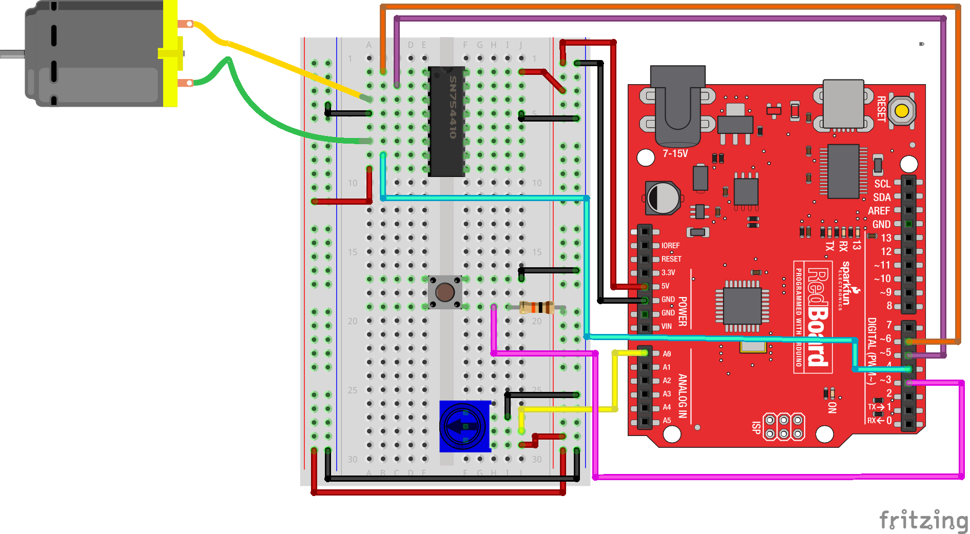
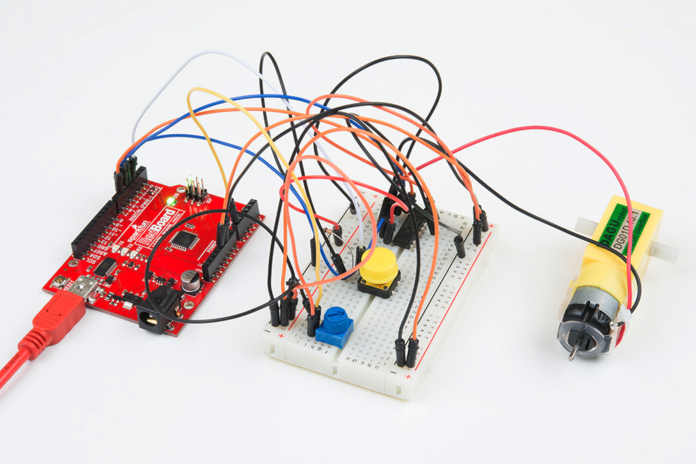
Hardware Hookup
Ready to start hooking everything up? Check out the wiring diagram below to see how everything is connected.
| Polarized Components | Pay special attention to the component’s markings indicating how to place it on the breadboard. Polarized components can only be connected to a circuit in one direction. |
Wiring Diagram for the Experiment
Open the Sketch
Open the Arduino IDE software on your computer. Coding in the Arduino language will control your circuit.
You can type out or copy and paste the following code into the Arduino IDE. Hit upload, and see what happens!
language:cpp
/*
SparkFun Tinker Kit
Example sketch 10

H-Bridge Motor Controller with Inputs

  Use the inputs to manually set the direction and speed of a motor.


This sketch was written by SparkFun Electronics,
with lots of help from the Arduino community.
This code is completely free for any use.
Visit http://learn.sparkfun.com/products/2 for SIK information.
Visit http://www.arduino.cc to learn more about Arduino.
*/
 //define the two direction logic pins and the speed / PWM pin
 const int DIR_A = 5;
 const int DIR_B = 4;
 const int PWM = 6;

 //define the input pins
 const int switchPin = 3;
 const int potPin = 0;

 void setup()
 {
  //set all pins as output
  pinMode(DIR_A, OUTPUT);
  pinMode(DIR_B, OUTPUT);
  pinMode(PWM, OUTPUT);
  //set the switchPin as INPUT
  pinMode(switchPin, INPUT);
  }

void loop()
{
//read the value from the potentiometer and divide
//it by 4 to get a 0-255 range. Store the value in
//the speed variable
int speed = analogRead(potPin) / 4;

 //read the value of the switch and store it in the
 //direction variable.


//if the value of direction is HIGH drive forward at
//a speed set by the speed variable, else drive reverse
//at a speed set by the speed variable.
if (digitalRead(switchPin) == HIGH)
{
  forward(speed);
}
else
 {
 reverse(speed);
 }
}

//create a custom function that defines moving forward
//the forward() function accepts one parameter and that is
//the speed at which you want to drive forward (0-255)
 void forward(int spd)
 {
 //motor contoller direction pins set to forward
 digitalWrite(DIR_A, HIGH);
 digitalWrite(DIR_B, LOW);

  //write the speed by using the parameter of spd
 analogWrite(PWM, spd);
  }

//create a custom function that defines moving in reverse
//the reverse() function accepts one parameter and that is
//the speed at which you want to drive in reverse (0-255)
void reverse(int spd)
{
//set motor controller pins to reverse
digitalWrite(DIR_A, LOW);
digitalWrite(DIR_B, HIGH);

 //write the speed by using the parameter of spd
 analogWrite(PWM, spd);
 }
These big, scary functions take a single value as a parameter: speed. Each function then accepts that value and applies it to the analogWrite() function inside of the custom function. Custom functions are a great way to clean up your code and also make it more modular and useful in other applications. Watch out! You are halfway to writing your own library.
What You Should See
You should be able to control the motor's direction by flipping the SPDT switch and then the speed through the potentiometer. Go ahead and play with both inputs to make sure they both work and the motor is responding to those inputs.
Troubleshooting
Motor Only Spins in One Direction
Double check the wiring of your switch, but also double check your if() statement to make sure there isn't a semicolon after the statement.
Experiment 11: Reading Serial Data
Introduction
In Experiment 3 you used an RGB LED to create a rainbow of fun. The problem is that, to define
colors, you had to change your Arduino code. You have also used the Serial object in Arduino
to print out data to your computer using Serial.print(); and Serial.println(). In this
experiment you will send serial data the other direction -- to the RedBoard! What data will you
be sending? Comma-separated RGB values to change the color of your RGB, of course!
Let's see what pot of gold lies on the other end of this data rainbow!
Parts Needed
You will need the following parts:
- 1x Breadboard
- 1x SparkFun RedBoard
- 1x Common Cathode RGB LED
- 3x 330Ω Resistors
- 6x Jumper Wires
Didn't Get the Tinker Kit?
If you are conducting this experiment and didn't get the Tinker Kit, we suggest using these parts:
Hardware Hookup
Ready to start hooking everything up? Check out the wiring diagram and hookup table below to see how everything is connected.
| Polarized Components | Pay special attention to the component’s markings indicating how to place it on the breadboard. Polarized components can only be connected to a circuit in one direction. |
Wiring Diagram for the Experiment
Open the Sketch
Open the Arduino IDE software on your computer. Coding in the Arduino language will control your circuit.
You can type out or copy and paste the following code into the Arduino IDE. Hit upload, and see what happens!
language:cpp
/*
SparkFun Tinker Kit
Example sketch 11

Serial Color Mixing

Read Serial data from your computer and use it to set
the RGB values of the RGB LED.


This sketch was written by SparkFun Electronics,
with lots of help from the Arduino community.
Visit http://learn.sparkfun.com/products/2 for SIK information.
Visit http://www.arduino.cc to learn about Arduino.
*/

//create variables for pin numbers. We are making them constants here, because they       //never change.
const int RED_PIN = 5;
const int GREEN_PIN = 6;
const int BLUE_PIN = 9;

// How fast we plan to cycle through colors in milliseconds
int redVal = 0;
int greenVal= 0;
int blueVal = 0;


void setup()
{
//set the three pin variables as outputs
pinMode(RED_PIN, OUTPUT);
pinMode(GREEN_PIN, OUTPUT);
pinMode(BLUE_PIN, OUTPUT);

//Start the Serial port at 9600 baud rate
Serial.begin(9600);
Serial.println("Please enter your RGB in CSV format(Example: 255,100,0)");
}


void loop()
{
analogWrite(RED_PIN, redVal);
analogWrite(GREEN_PIN, greenVal);
analogWrite(BLUE_PIN, blueVal);

if(Serial.available()>0)
 {
  redVal = Serial.parseInt();
  greenVal = Serial.parseInt();
  blueVal = Serial.parseInt();
 }
}
Code to Note
language:cpp
Serial.begin(9600);
Whether you are using serial communication as an input or an output, you need to use the begin() method to start your serial port. The baud rate can vary, but 9600 is the standard for most applications.
language:cpp
Serial.parseInt();
There are a number of ways to read and parse data coming in from the serial port. The simplest way is to format your data coming in as a Comma-Separated Value (CSV) string. In this format the parseInt() method captures the data as it comes in. Once the there is a non alpha-numeric character (a character that is not a letter or a number) parseInt() will stop capturing the value as an integer. As an example if we were to send the string 123,456,789 through parseInt() it would return the value of 123 because it would stop capturing at the comma (,).
In this experiment we use the parseInt() method three times, one right after the other, to capture the three comma-separated RGB values and place them in the three color variables.
What You Should See
You should see nothing at first when your upload is complete. Open up the Serial Monitor (The magnifying glass icon in the upper right-hand corner of the Arduino IDE). You should see the text "Please enter your RGB in CSV format(Example: 255,100,0)" print out in the serial monitor.
Enter an RGB value, (we are using 255,100,0 as an example) in the text entry area as shown below and click 'Send'. Once you click the send button your RGB should turn a purple color. Congrats! You just sent data to your RedBoard from your computer!
Troubleshooting
LED Remains Dark or Shows Incorrect Color
With the four pins of the LED so close together, it’s sometimes easy to misplace one. Double check each pin is where it should be.
You are Sending Data but Nothing Happens
Make sure you are sending your data as integers between 0 and 255 in a comma-separated format.
Resources and Going Further
Check out the SparkFun MESA Portal for more information about using the Tinker Kit for the MESA National Challenge. There are also, tons of sensors and shields that you can hook up to your RedBoard board to help take your projects to the next level. Here is some further reading that may help you along in learning more about the world of electronics.
For more info on Arduino, check out these tutorials:
- Arduino Resources and Curriculum
- Arduino Comparison Guide
- Arduino Shields
- Installing Arduino
- Installing an Arduino Library
- Arduino Data Types
For more hardware-related tutorials, give these a read: