Galileo Experiment Guide
This Tutorial is Retired!
This tutorial covers concepts or technologies that are no longer current. It's still here for you to read and enjoy, but may not be as useful as our newest tutorials.
 HelloTechie
 SIK Galileo - Part 1: Blinking an LED
Introduction
To help you get started with the Galileo, the SIK Galileo tutorials will take you through different basic circuits. In this tutorial, we will go over how to work with an LED.
LEDs are small, powerful lights that are used in many different applications. To start off, we will work on blinking an LED, the Hello World of microcontrollers. That's right - it's as simple as turning a light on and off. It might not seem like much, but establishing this important baseline will give you a solid foundation as we work toward more complex experiments.
Parts Needed
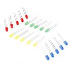
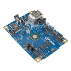
You will need the following parts:
- 1x Breadboard
- 1x Galileo
- 1x LED
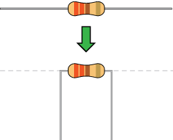
- 1x 330Ω Resistor
- 2x Jumper Wires
If you are following through all of the SIK Galileo tutorials we suggest using these parts:


View the SparkFun Inventor's Kit for Galileo wishlist, to see the parts needed to go through the all the experiments.
Suggested Reading
Before continuing on with this experiment, we recommend you be familiar with the concepts in the following tutorial:
- Light-emitting Diodes - Learn more about LEDs!
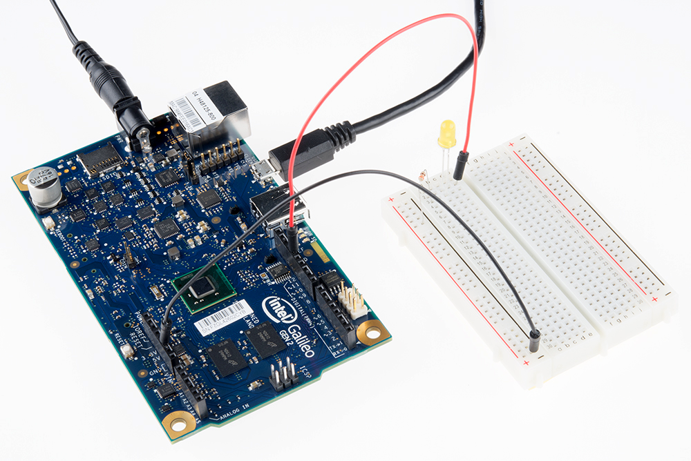
Hardware Hookup
Ready to start hooking everything up? Check out the Fritzing diagram and hookup table below, to see how everything is connected. Pay special attention to the component’s markings indicating how to place it on the breadboard. Polarized components are highlighted with a yellow warning triangle, in the table. Polarized components can only be connected to a circuit in one direction.
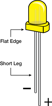
**Please note: Pay close attention to the LED. The negative side of the LED is the short leg, marked with a flat edge. **
Components like resistors need to have their legs bent into 90° angles in order to correctly fit the breadboard sockets. You can also cut the legs shorter to make them easier to work with on the breadboard.
Fritzing Diagram

Hookup Table
| Component | Galileo | Breadboard | Breadboard |
|---|---|---|---|
| LED | c2 ( + ) | c3 ( - ) | |
| 330 Resistor | a3 | ( - ) | |
| Jumper Wire | GND | ( - ) | |
| Jumper Wire | PIN 13 | e2 |
Code to Note
pinMode(13, OUTPUT);
Before you can use one of the Galileo's pins, you need to tell the Galileo whether it is an INPUT or OUTPUT. We use a built-in "function" called pinMode() to do this.
digitalWrite(13, HIGH);
When you're using a pin as an OUTPUT, you can command it to be HIGH (output 5 volts), or LOW (output 0 volts).
**Copy and paste the following code into the Arduino IDE. Hit upload, and see what happens! **
language:cpp
/*
SparkFun Inventor's Kit Galileo
Example sketch 01

BLINKING A LED

  Turn an LED on for one second, off for one second,
  and repeat forever.

Hardware connections:

  Most Arduinos already have an LED and resistor connected to
  pin 13, so you may not need any additional circuitry.

  But if you'd like to connect a second LED to pin 13, or use
  a different pin, follow these steps:

    Connect the positive side of your LED (longer leg) to Galileo
    digital pin 13 (or another digital pin, don't forget to change
    the code to match).

    Connect the negative side of your LED (shorter leg) to a
    330 Ohm resistor (orange-orange-brown). Connect the other side
    of the resistor to ground.

    pin 13 _____ + LED - _____ 330 Ohm _____ GND

    (We always use resistors between the Galileo and and LEDs
    to keep the LEDs from burning out due to too much current.)

This sketch was written by SparkFun Electronics,
with lots of help from the Arduino community.
This code is completely free for any use.
Visit http://www.arduino.cc to learn about the Arduino.

Version 2.0 6/2012 MDG
*/


// Welcome to the Galileo!

// If you're brand-new to this, there will be some new things to
// learn, but we'll jump right in and explain things as we go.

// The Galileo is a tiny computer that runs programs called
// "sketches". These are text files written using instructions
// the computer understances. You're reading a sketch right now.

// Sketches have computer code in them, but also (hopefully)
// "comments" that explain what the code does. Comments and code
// will have different colors in the editor so you can tell them
// apart.

// This is a comment - anything on a line after "//" is ignored
// by the computer.

/* This is also a comment - this one can be multi-line, but it
must start and end with these characters */

// A "function" is a named block of code, that performs a specific,
// well, function. Many useful functions are already built-in to
// the Galileo; others you'll name and write yourself for your
// own purposes.

// All Galileo sketches MUST have two specific functions, named
// "setup()" and "loop()". The Galileo runs these functions
// automatically when it starts up or if you press the reset
// button. You'll typically fill these function "shells" with your
// own code. Let's get started!


// The setup() function runs once when the sketch starts.
// You'll use it for things you need to do first, or only once:


void setup()
{
  // The Galileo has 13 digital input/output pins. These pins
  // can be configured as either inputs or outputs. We set this
  // up with a built-in function called pinMode().

  // The pinMode() function takes two values, which you type in
  // the parenthesis after the function name. The first value is
  // a pin number, the second value is the word INPUT or OUTPUT.

  // Here we'll set up pin 13 (the one connected to a LED) to be
  // an output. We're doing this because we need to send voltage
  // "out" of the Galileo to the LED.

  pinMode(13, OUTPUT);

  // By the way, the Galileo offers many useful built-in functions
  // like this one. You can find information on all of them at the
  // Galileo website: http://arduino.cc/en/Reference
}


// After setup() finishes, the loop() function runs over and over
// again, forever (or until you turn off or reset the Galileo).
// This is usually where the bulk of your program lives:


void loop()
{
  // The 13 digital pins on your Galileo are great at inputting
  // and outputting on/off, or "digital" signals. These signals
  // will always be either 5 Volts (which we call "HIGH"), or
  // 0 Volts (which we call "LOW").

  // Because we have an LED connected to pin 13, if we make that
  // output HIGH, the LED will get voltage and light up. If we make
  // that output LOW, the LED will have no voltage and turn off.

  // digitalWrite() is the built-in function we use to make an
  // output pin HIGH or LOW. It takes two values; a pin number,
  // followed by the word HIGH or LOW:

  digitalWrite(13, HIGH);   // Turn on the LED

  // delay() is a function that pauses for a given amount of time.
  // It takes one value, the amount of time to wait, measured in
  // milliseconds. There are 1000 milliseconds in a second, so if
  // you delay(1000), it will pause for exactly one second:

  delay(1000);              // Wait for one second

  digitalWrite(13, LOW);    // Turn off the LED

  delay(1000);              // Wait for one second

  // All together, the above code turns the LED on, waits one
  // second, turns it off, and waits another second.

  // When the computer gets to the end of the loop() function,
  // it starts loop() over again. So this program will continue
  // blinking the LED on and off!

  // Try changing the 1000 in the above delay() functions to
  // different numbers and see how it affects the timing. Smaller
  // values will make the loop run faster. (Why?)
}
What You Should See
You should see your LED blink on and off. If it isn't, make sure you have assembled the circuit correctly and verified and uploaded the code to your board, or see the troubleshooting section.
Real World Application
Almost all modern flat screen televisions and monitors have LED indicator lights to show they are on or off.
Troubleshooting
Program Not Uploading
This happens sometimes, the most likely cause is a confused serial port, you can change this in tools > serial port >
Still No Success?
A broken circuit is no fun, send us an e-mail and we will get back to you as soon as we can: techsupport@sparkfun.com